Transcription
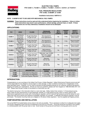
ELECTRIC FUEL PUMPSP/N 12-801-1, 712-801-1, 12-802-1, 712-802-1, 12-812-1, 12-815-1, & 712-815-1FUEL PRESSURE REGULATORSP/N 12-803, 12-803BP, & 12-804Installation Instructions 199R7914-3NOTE: 12-803BP IS NOT TO BE USED WITH MECHANICAL FUEL PUMPS!WARNING! These instructions must be read and fully understood before beginning the installation. Failure to followthese instructions may result in poor performance, vehicle damage, personal injury, or death. If theseinstructions are not fully understood, installation should not be 802-1712-802-112-812-112-815-1712-815-1Red ElectricFuel pump,Street Perf.Red ElectricFuel Pump,MarineBlue ElectricFuel Pump,CompetitionBlue Elec. FuelPump, Comp.MarineBlue ElectricFuel Pump,CompetitionBlack Elec.Fuel pump,Pro SeriesBlack Elec.Fuel pump,Pro SeriesMarineFLOWSPRESSUREREGULATORALC /METHCOMPAT.PRESETPRESSURESAFETYSWITCHSHUT-OFF97 gph (free flow)67 gph at 5 psiNot required formost applicationsNo7 PSIRecommended(P/N 12-810)97 gph (free flow)67 gph at 5 psiNot required formost applicationsNo7 PSIRecommended(P/N 12-810)110 gph (free flow)70 gph at 9 psiHigh pressure(12-803 provided)No14 PSIRecommended(P/N 12-810)110 gph (free flow)70 gph at 9 psiHigh pressure(12-803 provided)No14 PSIRecommended(P/N 12-810)110 gph (free flow)70 gph at 9 psiHigh pres. (use 12-803)High pres. bypass(use 12-803BP)No14 PSIRecommended(P/N 12-810)140 gph (free flow)120 gph at 9 psiRequiresP/N 12-704Yes14 PSIRecommended(P/N 12-810)140 gph (free flow)120 gph at 9 psiRequiresP/N 12-704Yes14 PSIRecommended(P/N d Fuel RegulatorCarbureted Fuel RegulatorCarbureted Bypass RegulatorPRESSURERANGE4-1/2 to 9 PSI1 to 4 PSI4-1/2 to 9 PSIINLET/OUTLETSIZE3/8” NPT Ports3/8” NPT Ports3/8” NPT PortsRESTRICTION.220” (7/32”).220” (7/32”).312” (5/16”)INTRODUCTION:Congratulations on your purchase of the Holley Fuel Pump or Holley Regulator! Holley Performance Products cannot and willnot be responsible for any alleged or actual engine or other damage, or other conditions resulting from misapplication of theparts described herein. However, it is our intent to provide the best possible products for our customer; products that performproperly and satisfy your expectations. Should you have any questions, please call Tech Support at 1-866-464-6553, M-F, 8-6CST. Please have the part number of the product on hand when you call.The electric fuel pump in this instruction sheet is a vane rotor type. Holley makes three versions: 1) A low-pressure pump,which meets the flow requirements of most passenger vehicles; 2) A high-pressure pump, which is mainly used for highperformance applications and comes with a fuel pressure regulator; and 3) A second high-pressure pump that allows an evenhigher flow rate and is alcohol and methanol compatible (regulator not included). A separate fuel pressure regulator must bepurchased. The bracket mounting holes are untapped on the above Holley regulators. Use the supplied self-tapping screws.PUMP MOUNTING AND INSTALLATION:The pump MUST be located below and as close to the tank as possible. This is necessary to allow for an adequate fuel supply.The pump is designed to push fuel and not designed to pull fuel out of the tank. The pump should be mounted on the chassis,in a vertical position with the pump motor on top. Avoid contact of the pump and fuel lines to moving parts and to any hot
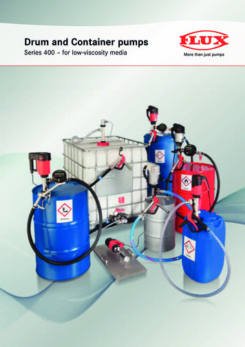
areas, such as the exhaust. The pump should not be mounted in a closed area, such as the vehicle’s trunk. Follow the stepsbelow for mounting the pump.WARNING! THE PUMP MUST BE LOCATED SO THAT INTERFERENCE BETWEEN THE VEHICLE’S BODY AND ITSCHASSIS MOVEMENT IS AVOIDED. THE PUMP AND ITS CONNECTING HOSES MUST NOT BE SUBJECTEDTO LOW GROUND CLEARANCE, WHERE ANY FLYING ROCKS OR ROAD DEBRIS CAN CAUSE DAMAGE.FAILURE TO AVOID THESE HAZARDS WILL LEAD TO PUMP DAMAGE, WHICH COULD RESULT IN FIRE,PROPERTY DAMAGE, SERIOUS INJURY, AND/OR DEATH.1.Select a mounting site below and as close as possible to the fuel supply and away from possible sources of heat, asdetailed previously.2.Use the mounting bracket (supplied) as a template and drill two clearance holes for 5/16” bolts.3.Place the rubber gaskets (supplied) between the mounting bracket and motor housing, then mount the pump in the verticalposition (motor on top) using two 5/16” bolts.4.Connect the fuel line from the tank to the fuel filter and the filter to the inlet port of the pump. Connect the carburetor feedline to the outlet port of the pump. Use of 3/8” fuel hose is recommended. Avoid unnecessary restrictions such as sharpbends and undersized fuel fittings and hoses. Avoid routing fuel lines in areas that would cause damage. All fuel lineconnections must be leakproof.WARNING! DO NOT OVERTIGHTEN THE FITTINGS ON THE FUEL PUMP OR REGULATOR. ASSEMBLY TORQUESHOULD NOT EXCEED 40 FT./LBS. THIS CAN BE ACHIEVED BY HAND TIGHTENING THE FITTING,FOLLOWED BY WRENCH TIGHTENING AN ADDITIONAL 3/4 OF 1 TURN AND THE AMOUNT NECESSARYTO POSITION THE FITTING IN THE CORRECT ORIENTATION. OVERTIGHTENING OF THE FITTINGS CANCAUSE PARTS TO CRACK, ALLOWING FUEL TO LEAK. A FUEL LEAK CAN CAUSE A FIRE AND/OREXPLOSION RESULTING IN PROPERTY DAMAGE, SERIOUS INJURY, AND/OR DEATH. THE USE OF ATHREAD SEALANT WITH PTFE IS REQUIRED FOR A PROPER SEAL. DO NOT USE A SILICONE-BASEDSEALANT OR PTFE TAPE.NOTE: For performance vehicles, 3/8” I.D. hose is recommended. We strongly urge the use of a coarse screen-type filterbefore the pump and a high quality filter after the pump.NOTE: Marine “712-xxx” fuel pumps have a vapor tube on the base of the pump. This tube should be hooked to a directvacuum source on the engine. This is a safety feature for marine applications, so that in the event of a fuel leakinternally in the pump, the fuel will be pulled into the engine and not leak into the bilge.5.If the original mechanical fuel pump is not going to be used or removed, disconnect the fuel lines from the pump andsecurely plug the inlet and discharge ports with plugs to deactivate the pump. Connect the original suction line to the outletline, bypassing the pump from the circuit.6.If the mechanical fuel pump is removed, seal the opening with a fuel pump block-off plate and gasket.USING A FUEL PRESSURE REGULATOR WITH A FUEL PUMP:NOTE: If the pump is a high-pressure model, a pressure regulator must be installed in the line between the pump and thecarburetor.NOTE: The mounting holes are untapped on these regulators. Use the supplied self-tapping screws.1.Using the bracket supplied with the regulator, position the regulator as close to the carburetor as possible, taking care tominimize the exposure to heat sources. DO NOT mount the regulator on the exhaust manifold or any extremely hotsurface.2.The standard regulator, provided with the 12-802-1 pump, has two discharge (out) ports (see Figure 1). In dual carburetorinstallations, one port can feed each carburetor. With single carbs, plug one port and feed the carburetor from the other.Either may be used. Installations should determine choice. See Figure 1.3.The 12-803BP bypass regulator has one bypass or return port. This port (labeled “RET”) must be connected to the fueltank with a fuel line the same size as the supply line (3/8” I.D. is recommended). See Figures 2 & 3.2
Figure 1Figure 2Figure 34.Connect the fuel line from the “out” side of the pump to the “in” side on the regulator. All fuel line connections must beleakproof.5.Connect the other line per Figure 2 or 3.6.The regulator comes from Holley with the regulator pressure preset (see table). However, for individual requirements, itmay be readjusted. Loosening the regulator locknut and turning the adjustment screw clockwise increases the pressure.Decrease pressure by turning the adjustment screw counter-clockwise.WARNING! TURNING THE ADJUSTMENT SCREW ALL THE WAY IN WILL RESULT IN EXCESSIVE FUEL PRESSUREAND CAUSE THE CARBURETOR TO FLOOD. A FLOODED CARBURETOR CAN CAUSE A FIRE AND/OREXPLOSION RESULTING IN PROPERTY DAMAGE, SERIOUS INJURY, AND/OR DEATH. ALWAYS USE AFUEL PRESSURE GAUGE BETWEEN THE REGULATOR AND THE CARBURETOR(S) WHEN ADJUSTINGTHE FUEL PRESSURE REGULATOR.NOTE: Any change made in fuel pressure will change the fuel bowl float level requirements. A readjustment in fuel bowllevels will be required for proper operation of the fuel system.WIRING THE FUEL PUMP:NOTE: A fuel pump can be wired as shown in Figure 4, but the preferred method is wiring it through a relay, as shown inFigure 5.1.Disconnect the ground cable from the battery.2.Connect the fuel pump (red lead) to a 12-volt ignition source. In this line, add an in-line fuse holder and a 7.5 amp fuse.3.To complete the installation, connect the ground (black lead) to the battery.3
Figure 4WIRING THE FUEL PUMP WITH A RELAY:NOTE: You will need Holley Fuel pump relay kit P/N 12-753 or equivalent 4-wire relay.1.Disconnect the cables from the battery.2.Mount relay on firewall of engine compartment using a sheet metal screw.WARNING! Before punching or drilling a hole in the firewall, make sure you know what is on the other side to avoidpuncturing equipment such as heater cores, air-conditioning system equipment, hoses, or wiring.3.Plug the fuel pump relay harness into the relay, until it locks into place.4.Connect the black wire of the harness to ground.5.Connect the Green/Black wire to a switched 12V source.6.Connect one of the red wires to the positive wire (red wire) of the fuel pump.7.Attach the in-line fuse holder to the remaining red wire. After attaching the fuse holder, insert the 15A fuse and connect tothe positive side of the battery.8.Reconnect the battery cables.Figure 5WIRING THE FUEL PUMP WITH AN OIL PRESSURE SAFETY SWITCH:One method is to wire the pump to a switched 12-volt source (providing power only when the engine is running) located at thevehicle’s electric panel. To ensure this condition, the installation of a Holley 12-810 oil pressure safety switch is recommendedfor installation into the wiring circuit. This will ensure that the pump will not continue to operate after the engine is shut offand/or when the key is left in the “ON” position. If the pressure switch is to be used, follow the installation instructions asoutlined below (refer to Figure 6).1.Disconnect the ground cable from the battery.2.Remove the original equipment oil pressure switch and retain.3.Screw a 1/8” pipe nipple into the hole from which the original pressure switch was removed. Use any suitable threadsealant on all fittings, taking care to avoid any excess that might contaminate the engine.4.Screw a 1/8” pipe tee onto the nipple and position it in a manner to facilitate the installation of the original oil pressureswitch and the new oil pressure safety switch in the remaining two holes.4
5.Screw in the two switches and reconnect the lead to the original equipment oil pressure switch.NOTE: The pump oil pressure switch will normally have three terminals marked: C (common), NC (normally closed), and NO(normally open).Figure 6 (w/ Holley fuel pump relay 12-753)6.Mount relay on firewall of engine compartment using a sheet metal screw.WARNING! Before punching or drilling a hole in the firewall, make sure you know what is on the other side to avoidpuncturing equipment such as heater cores, air-conditioning system equipment, hoses, or wiring.7.Plug the fuel pump relay harness into the relay, until it locks into place.8.Connect the black wire of the relay harness to a good clean ground using 12 gauge wire.9.Connect the Green/Black wire of the relay harness to the terminal marked “C” on the oil pressure safety switch.10. Connect one of the red wires of the relay harness to the positive wire (red wire) of the fuel pump.11. Connect the black wire of the fuel pump to a good clean chassis ground using a ring terminal12. Attach the in-line fuse holder to the remaining red wire of the relay harness. After attaching the fuse holder, insert a 25Afuse and connect to the positive side of the battery using 12 gauge wire.13. Connect the terminal marked “NO” of the safety switch to a switched 12V source.14. Connect the terminal marked “NC” of the safety switch to the starter terminal that’s hot (12V) during cranking only.15. Reconnect the battery cables.Oil Pressure Safety SwitchP/N 12-810Fuel Pressure RegulatorFuel Pressure RegulatorFor High Performance Pump P/N 12-803For High Performance Pump P/N 12-704MAINTENANCE AND CLEANING INSTRUCTIONS FOR ELECTRIC FUEL PUMPS:Due to the current poor quality gasoline that’s available, it is recommended that periodically a can of dry gas be used to absorbthe water out of the fuel delivery system. The fuel filter element should be blown clean with compressed air every 6,000 milesand replaced every 12,000 miles to assure maximum protection. If your fuel pump fails to pump or fails to maintain adequatepressure, check the following:1.Check the voltage at the pump to ensure 12-volt supply.2.If this doesn’t solve the problem, turn the pump on and listen for a hum from the top of the pump. If there is no hum, thepump’s electrical system should be checked by a competent mechanic. If the pump hums, it probably only needs to becleaned.3.Check the fuel line (especially the fuel filter) for any obstruction. Use compressed air to blow the line free.5
CLEANING THE PUMP:The following is a step-by-step procedure for cleaning the Holley electric fuel pumps. Do all disassembling on a clean bench.Read all instructions thoroughly and completely before starting.1.Remove the pump from the car.2.Remove the 5 bolts from the bottom of the pump.3.Holding the pump in position, remove the bottom plate. Remove the upper plate gasket and rotor stop plate. Note theposition of the rotor, rotor vanes, screen, and relief valve arrangement for re-installation.Figure 7Figure 84.Remove the screen (note the position of the screen). Remove the rotor vanes and rotor by inverting the pump. Lay allpieces on a flat clean surface. See Figure 7.5.Remove the pressure relief screw. The screw is spring loaded. Remove the spring and relief plunger.6.Clean the base housing with any good quality carburetor cleaner (spray-type only). Blow the base dry with compressed air.Clean any loose PTFE tape, etc. from the inlet and outlets.WARNING! DO NOT IMMERSE THE ENTIRE UNIT IN ANY LIQUID. IMMERSION COULD DAMAGE THE ELECTRICALCIRCUITRY, RESULTING IN A PUMP MALFUNCTION. A PUMP MALFUNCTION COULD RESULT IN A FIRE,WHICH MAY RESULT IN PROPERTY DAMAGES, SERIOUS INJURY, OR DEATH.7.If the relief plunger is rusty, clean it with emery paper. The plunger must slide freely in the base. Check the plunger,spring, and o-ringed screw. Check that plunger is free in the passage. See Figures 8 and 9.Figure 98.Clean the rotor vanes with emery paper. The vanes must slide freely in the rotor slot. Check that the vanes move freely.Replace the rotor stop plate. Install the flame arrestor making sure the screen is behind the screen stop. Replace theupper plate gasket and upper plate. Fasten with five screws.9.Reinstall the pump in the car.Technical Service: 1-866-464-6553www.holley.com 2008 Holley Performance Products, Inc. All rights reserved.199R7914-3Revision Date: 12-16-13
12-801-1 Red Electric Fuel pump, Street Perf. 97 gph (free flow) 67 gph at 5 psi Not required for most applications No 7 PSI Recommended (P/N 12-810) 712-801-1 Red Electric Fuel Pump, Marine 97 gph (free flow) 67 gph at 5 psi Not required for most applications No 7 PSI Recommended (P/N 12-810) 12-802-1 Blue Electric Fuel Pump, Competition