Transcription
BNI IOL-801-102-Z036BNI IOL-801-102-Z037Smart LightUser’s Guide
Content1Notes to the user1.1 Structure of the guide1.2 Typographical es1.3 Symbols1.4 Abbreviations1.5 Deviating views33333333332Safety2.1 Intended use2.2 Installation and startup2.3 General safety instructions2.4 Resistance to aggressive substancesHazardous voltage4444443Getting Started3.1 Overview BNI IOL-801-102-Z0363.2 Overview BNI IOL-801-102-Z0373.3 Mechanical connection3.4 Electrical connection3.5 Function ground3.6 IO-Link connectionSmart Light connectionModule versions3.7 Short description of the functionality3.8 Segment mode3.9 Level mode3.10 Runlight mode3.11 Flexible mode3.12 Synchronisation5567777778881111114IO-Link Interface4.1 IO-Link Data4.2 Process data / Input dataBNI IOL-801-102-Z036Error codes4.3 Process data / Output dataBNI IOL-801-102-Z03x, Segment ModeBNI IOL-801-102-Z03x, Level ModeBNI IOL-801-102-Z03x, Runlight ModeBNI IOL-801-102-Z03x, Flexible Mode4.4 Parameter data/ Request dataLevel resolution 43hexLevel mode limit x-y 49hex 4AhexSupply monitoring 50hexBrightness 51hexSetting the serial number 54hexOperating Hours Counter 57hexBoot Cycle Counter 58hexDevice Temperature 59hexFlexible mode, LEDxx settings A1hex AChexSafe State FBhexUser color FChexLimit type FDhex4.5 Errors4.6 303030www.balluff.com1
Balluff / IO-Link BNI IOL-801-102-Z03x4.7 RGB Color315Technical Data5.1 Dimensions5.2 Mechanical data5.3 Electrical data5.4 Operating conditions5.5 LED indicatorStatus LED323232323233336Appendix6.1 Product ordering code6.2 Order informationIncluded material34343434www.balluff.com2
Balluff / IO-Link BNI IOL-801-102-Z03x1Notes to the user1.1 Structure of theguideThe guide is organized so that the sections build on one another.Section 2: Basic safety information.Section 3: The main steps for installing the device. 1.2 TypographicalconventionsThe following typographical conventions are used in this Guide.EnumerationsEnumerations are shown in list form with bullet points. Entry 1, Entry 2.ActionsAction instructions are indicated by a preceding triangle. The result of an action is indicatedby an arrow. Action instruction 1. Action result. Action instruction 2.SyntaxNumbers:Decimal numbers are shown without additional indicators (e.g. 123),Hexadecimal numbers are shown with the additional indicator hex (e.g. 00hex).Cross-referencesCross-references indicate where additional information on the topic can be found.1.3 SymbolsAttention!This symbol indicates a security notice which must be observed.NoteThis symbol indicates general notes.1.4Abbreviations1.5 Deviating viewswww.balluff.comBNIDPPEMCFEIOLISDUBalluff Networking InterfaceDirect Parameter PageElectromagnetic CompatibilityFunction EarthIO-LinkIndexed Service Data UnitProduct views and illustrations in this guide may differ from the actual product. They areintended only as illustrative material.3
Balluff / IO-Link BNI IOL-801-102-Z03x2Safety2.1 Intended use2.2 Installation andstartup2.3 General safetyinstructions2.4 Resistance toaggressivesubstancesHazardousvoltageThis guide describes the Balluff BNI IOL-801-102-Z03x for the application as status lightmodule. Hereby it is about an IO-Link device which communicates by means of IO-Linkprotocol with the superordinate IO-Link master assembly.Attention!Installation and startup are to be performed only by trained specialists. Qualifiedpersonnel are persons who are familiar with the installation and operation of theproduct, and who fulfills the qualifications required for this activity. Any damageresulting from unauthorized manipulation or improper use voids themanufacturer's guarantee and warranty. The Operator is responsible forensuring that applicable of safety and accident prevention regulations arecomplied with.Commissioning and inspectionBefore commissioning, carefully read the operating manual.The system must not be used in applications in which the safety of persons is dependent onthe function of the device.Authorized PersonnelInstallation and commissioning may only be performed by trained specialist personnel.Intended useWarranty and liability claims against the manufacturer are rendered void by: Unauthorized tampering Improper use Use, installation or handling contrary to the instructions provided in this operatingmanualObligations of the Operating CompanyThe device is a piece of equipment from EMC Class A. Such equipment may generate RFnoise. The operator must take appropriate precautionary measures. The device may only beused with an approved power supply. Only approved cables may be used.MalfunctionsIn the event of defects and device malfunctions that cannot be rectified, the device must betaken out of operation and protected against unauthorized use.Intended use is ensured only when the housing is fully installed.Attention!The BNI modules generally have a good chemical and oil resistance. Whenused in aggressive media (eg chemicals, oils, lubricants and coolants each inhigh concentration (ie, low water content)) must be checked prior applicationrelated material compatibility. In the event of failure or damage to the BNImodules due to such aggressive media are no claims for defects.Attention!Disconnect all power before servicing equipment.NoteIn the interest of product improvement, the Balluff GmbH reserves the right tochange the specifications of the product and the contents of this manual at anytime without notice.www.balluff.com4
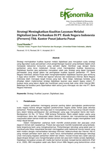
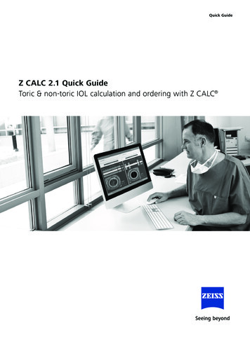
Balluff / IO-Link BNI IOL-801-102-Z03x3Getting Started3.1 Overview BNI IOL801-102-Z0361201921817161531413121141098576Fig. 3-1: BNI IOL-801-102-Z03612345678www.balluff.comCapSegment 1Segment 2Segment 3SocketM12 connectorM18 thread for mountingStatus 8LED07LED06LED05LED04LED03LED02LED015
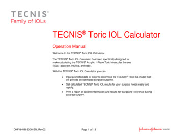
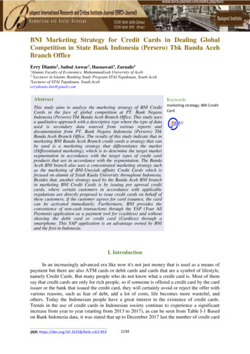
Balluff / IO-Link BNI IOL-801-102-Z03x3Getting Started3.2 Overview BNI IOL801-102-Z0371201921817161531413121141089576Fig. 3-2: BNI IOL-801-102-Z03712345678www.balluff.comCap with buzzerSegment 1Segment 2Segment 3SocketM12 connectorM18 thread for mountingStatus 8LED07LED06LED05LED04LED03LED02LED016
Balluff / IO-Link BNI IOL-801-102-Z03x3Getting Started3.3 MechanicalconnectionThe BNI IOL-801-102-Z03x modules are attached by using an M18 nut.3.4 ElectricalconnectionThe BNI IOL-801-102-Z03x modules require no separate supply voltage connection. Poweris provided through the IO-Link interface by the host IO-Link Master.3.5 Function groundFE terminalwith a screwto connectprotectiongroundNoteThe FE connection from the housing to the machine must be low-impedanceand as short as possible. There is no need to use an additional FE connection ifa low impedance connection to FE can be assured through the M18 Smart Lightconnector thread.3.6 IO-LinkconnectionSmart LightconnectionIO-Link (M12, A-coded, male)PinFunction1Power supply controller, 24V2-3GND, reference potential4C/Q, IO-Link Data transmission channel Connection protection ground to FE terminal, if present. Connect the incoming IO-Link line to the Smart Light.NoteA standard 3 wire sensor cable is used for connecting to the host IO-Linkmaster.Module versionsVersionBNI IOL-801-102-Z036BNI IOL-801-102-Z037www.balluff.comDescriptionMaximum 3 segment configurable signal light withlevel meter, runlight mode and flexible mode.Maximum 3 segment configurable signal light withlevel meter, runlight mode, flexible mode and buzzer.7
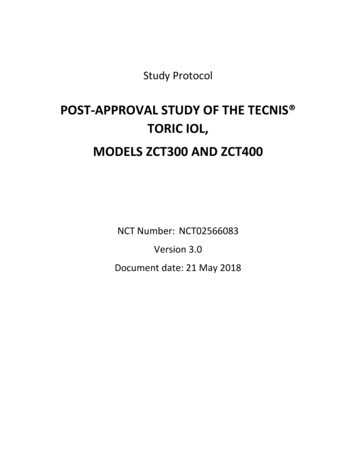
Balluff / IO-Link BNI IOL-801-102-Z03x3Getting Started3.7 Short descriptionof thefunctionalityThe functionality of the Balluff status light module can be controlled through process dataand ISDU registers. It has four main mode of functionality: Segment mode Level mode Runlight mode Flexible mode*With the help of these four modes various warning and indication signals can be indicated.The buzzer function is available in all modes. The synchronisation* is available in segmentand runlight mode and if the Smartlight contains buzzer it is also available in level andflexible mode.3.8 Segment modeTo use the module as a standard status light, the corresponding byte (Mode select) mustbe written with the proper value in the process data. The process data controls the color ofeach segment. In the segment mode the module can be used as a standard status light,with configurable number of segments. Maximum three segments can be set. Irrespectivelyof the selected number of segments, always all of the LEDs are used as a display element.The number of the segments can be set any number between 1 and 3. The module has 12LEDs, which are equally distributed between the segments. The color of each segment canbe selected from a color table, which has six pre-defined colors and one user defined color.The combinations of the pre-defined colors are not limited. In the segment mode, thesegments can be set to blink too. Each segment has two control bits in process data, whichdetermine the blinking state of the corresponding segment and the type of the blinking. Theblinking has two modus. Either normal blinking or flash mode can be selected. In normalblinking the LEDs are switched on and off periodically with a 50% duty cycle. In the flashmode, the LEDs are switched on and off quickly three times. The flash is repeated in everysecond. The frequency of the normal blinking can be changed too.3.9 Level modeIn level mode the complete module works as one indicator element. In this case a levelvalue can be displayed. The higher value the module becomes, the more LEDs will beswitched on. This mode can be used as a level indicator, for example to indicate a fluidlevel in a tank. The number of the LEDs switched on depends on the input level. In the levelmode process data gives the level. The resolution of the input level can be selected from 8bit up to 16 bit.In the level mode various parameters can be controlled through the process data or ISDUregisters. These ISDU parameters should be set before the level mode is used. The leveldisplay can be selected to be bottom-up or top-down. In the bottom-up mode the levelindicator increases from the bottom of the module. In the top-down mode the indicatorincreases from the top of the module.Although there are no real segments in the level mode, because the LEDs are controlled bythe input level, the LEDs are divided into three virtual segments. These virtual segmentscan have their own color. The color of these segments can be set in the process data. So itcan be realized, that the level meter can have more colors (up to the maximum number ofthe segments). Some or all colors can be set as dominant color. This means, when theinput level is high enough to switch on the next LED and this LED is in another virtualsegment, the LEDs, which are under the actual LED, take over the color of the actual LED.In this case, as the input level increases, the color of the full LED bar can be changed.For example:The lower segment is green, the middle segment is yellow and the upper segment is red.The LEDs are shown in the next figures, when the Smartlight level mode is configureddifferently.*Available from software version 3.0www.balluff.com8
Balluff / IO-Link BNI IOL-801-102-Z03x3Getting StartedThe LED bar at increasing input data and no color dominance. (The virtual segments can beseen on the left side.)Seg. 1Seg. 2Seg. 3www.balluff.com9
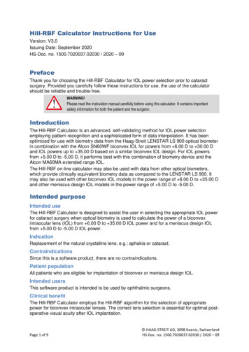
Balluff / IO-Link BNI IOL-801-102-Z03x3Getting StartedThe LED bar at increasing input data, all the colors are dominant.Seg. 1Seg. 2Seg. 5www.balluff.com10
Balluff / IO-Link BNI IOL-801-102-Z03x3Getting StartedBy default the 12 LEDs are divided into equal virtual segments. The height of the virtualsegments can be modified too. There are two ISDU registers (Level mode limit x-y ISDUregister), in which the limits of the virtual segments can be modified. For example: If theinput level value is higher than the limit value of the 2. and 3. segment (Level mode limit 23), the current LED will become the color of the Level mode segment 2 color. The limits canbe given either in percent or in absolute value.The LED bar at increasing input data, there is no color dominance. The limits of thesegments are modified, so they are not equally distributed.Seg. 1Seg. 2Seg. 33.10 Runlight modeIn the runlight mode, the complete module displays a running light effect. In this case all ofthe LEDs are working as one runlight effect. The process data defines the color of therunning segment, the background color and the speed of the segment. One segment has asize of 4 LEDs.3.11 Flexible modeIn the flexi mode each LED-ring can be configured individually. With BNI IOL-801 youcan realize up to 12 different segments. To use the flexi mode, the ISDU register must beset to flexi mode. There is an ISDU register for each LED ring, which has 5 subindices, 3for the color channels, one for brightness ON and one for brightness OFF. In the processdata there is one bit for every LED-ring, which sets the LED state (ON or OFF)3.12 SynchronisationIn synchronisation mode you can syncronise functions (blinking, flashing, buzzer) of severalBalluff SmartLights. The function is available in runlight- and segment mode. Thesynchronisation is controlled by 2 bits in the process data: (Sync Start and Sync Impluse).When a rising edge is detected on the Sync start bit, the SmartLight resets its internal state.This assures that the syncronised SmartLights start to work in the same state. The Syncstart rising edge has to be generated once after a reset. When a rising edge is detected onthe Sync impulse bit, the SmartLight resets its internal timer. It has to be generatedcyclically in order to keep the SmartLights synchronised. The time period of the Syncimpluse can be configured by the user. It s recommended to set the values between 1 sec.and 15 sec., depending on the frequency of the synchronised parameters (blinking,flashing, buzzer).www.balluff.com11
Balluff / IO-Link BNI IOL-801-102-Z03x4IO-Link Interface4.1 IO-Link Data4.2 Process data /Input dataError codesCOM2 (38,4 kBaud)7.2 ms8 Byte output, 1 Byte input1.12.V7.2 ms1.017.2 msThe BNI IOL-801-102-Z03x has one byte input process data. The input process data containsthe error value for configuration errors. There are different errors, which can be present at thesame time, but only the error code with the highest priority will be send in the input processdata.ByteBitDescriptionBNI IOL-801102-Z036BNI IOL-801-102-Z03xData transmission rateMinimal cycle timeProcess data lengthIO-Link RevisionFrame typeProcess data cycle time** by min. cycle time076543210Error code0x00 – No error0x01 – Wrong mode selected0x02 – Level value out of range0x04 – Wrong number of segments selected0x05 – Wrong frequency selected0x06 – Wrong speed selected0x07 – Wrong buzzer function selected (Only in case of BNI IOL-801-102-Z037)An error code (values from 0x01 to 0x07) with lower value has higher priority than error codewith higher value.4.3 Process data /Output datawww.balluff.comThe BNI IOL-801-102-Z03x has 8 byte output process data. The output process data hasdifferent meaning depending on the selected mode (segment mode, level mode, runlight modeor flexible mode). The byte 3 has a special meaning in the output process data. It is commonfor all modes. The mode of the Smart Light can be selected and the synchronisation can becontrolled with the help of this byte.12
Balluff / IO-Link BNI IOL-801-102-Z03xIO-Link Interface43210Segment 1color5Segment 1 blink61-7654210Segment 3color-ByteBit3Segment 3 blink-4-5-6Buzzer state7Description21-Bit 0-2/4-6, Segment color000 Off001 Green010 Red011 Yellow100 Blue101 Orange*110 User defined*111 White*color is available from software version 2.10-3-BuzzerType2-DescriptionByteBit07Segment 2colorByteBitDescriptionBNI IOL-801-102Z03x,Segment ModeSegment 2 blink4Bit 4-5, Buzzer type(Only in case of BNI IOL-801-102-Z037)00 Continuous sound01 1 Hz chopped sound10 5 Hz chopped sound11 3 short beep, 2 sec pauseBit 7, Buzzer state(Only in case of BNI IOL-801-102-Z037)0 – Buzzer is off1 – Buzzer is onBit 3, Segment blink0 – Segment does not blink1 – Segment blinks according to the blinkmodus settingswww.balluff.com13
Balluff / IO-Link BNI IOL-801-102-Z03xIO-Link Interface3210Segment Mode3Level Mode4Runlight Mode5-6-7Sync start*DescriptionBitSync impulse*ByteFlexible Mode*4The operating mode of the Smart Light can be selected in the Byte 3. Only one bit shouldbe set at the same time from the mode bits (bit0-3). The Sync start/impulse bits are risingedge sensitive. The Smart Light stays in the last Modus, when the operating mode is set on0x00.Byte476DescriptionBit54106543210----Blink mode Segment 3Blink mode Segment 2Blink mode Segment 157-Description2Number of segments(1 – 3)ByteBit3Blink mode segment X0 – The segment is blinking with a 50% duty cycle1 – The segment is flashing.*Available from software version 3.0www.balluff.com14
Balluff / IO-Link BNI IOL-801-102-Z03x4IO-Link InterfaceByte676DescriptionBit543210Blinking frequency(1 – 5)0x01 – 0.5 Hz0x02 – 1 Hz0x03 – 2 Hz0x04 – 5 Hz0x05 – 10 HzByteDescriptionBit776543210Buzzer volume**(0-255)0: minimum volume255: maximum volume**Available from software version 4.0www.balluff.com15
Balluff / IO-Link BNI IOL-801-102-Z03x54320Segment 1color11-7654210Segment 3color-ByteBit3Segment 3dominance-4-5-6Buzzer ent 1dominance7Segment 2colorByteBitBuzzerTypeBNI IOL-801-102Z03x, Level ModeSegment 2dominanceIO-Link InterfaceDescription4Bit 0-2/4-6, Segment color000 Off001 Green010 Red011 Yellow100 Blue101 Orange*110 User defined*111 White*color is available from software version 2.1Bit 4-5, Buzzer type(only by BNI IOL-801-102-Z037)00 Continuous sound01 1 HZ chopped sound10 5 Hz chopped sound11 3 short beep, 2 sec pauseBit 7, Buzzer state(only by BNI IOL-801-102-Z037)0 – Buzzer is off1 – Buzzer is onBit 3 / 7, Segment dominance0 – Segment is not dominant1 – Segment is dominantwww.balluff.com16
Balluff / IO-Link BNI IOL-801-102-Z03xIO-Link Interface-3210Segment Mode4Level Mode5Runlight Mode6-37Sync start*DescriptionBitSync impulse*ByteFlexible Mode*4The operating mode of the Smart Light can be selected in the Byte 3. Only one bit shouldbe set at the same time from the mode bits (bit0-3). The Sync start/impulse bits are risingedge sensitive. The Smart Light stays in the last Modus, when the operating mode is set on0x00.4210Level type53-4-5-6-47-DescriptionByteBit32100 – bottom – up1 – top - down57DescriptionByteBitDescriptionByteBit6Level value (16 bit) – Low byte676543210Level value (16 bit) – High byte*Available from software version 3.0www.balluff.com17
Balluff / IO-Link BNI IOL-801-102-Z03x4IO-Link InterfaceByte77DescriptionBit6543210Buzzer volume**(0-255)0: minimum volume255: maximum volumeLevel value (16 bit) – High byte1413121110987level value (16 bit) – Low byte6543210LSB8 bit level value14 bit level value16 bit level valueLSB12 bit level valueLSB10 bit level valueLSBLSBMSB MSB MSB MSB MSB15Level value: 8, 10, 12, 14 or 16 bit value for level indicator. The resolution can be set inLevel resolution ISDU register. The Level value is always left justified.**Available from software version 4.0www.balluff.com18
Balluff / IO-Link BNI IOL-801-102-Z03xIO-Link --ByteBit3--4-5-6Buzzer unningcolorByteBitDescriptionBNI IOL-801-102Z03x,Runlight Mode-4Bit 0-2 / 4-6, Background Color / RunningcolorBit 7, Buzzer state(only by BNI IOL-801-102-Z037)000 Off001 Green010 Red011 Yellow100 Blue101 Orange*110 User defined*111 White0 – Buzzer is off1 – Buzzer is on*color is available from software version 2.1Bit 4-5, Buzzer type(only by BNI IOL-801-102-Z037)00 Continuous sound01 1 HZ chopped sound10 5 Hz chopped sound11 3 short beep, 2 sec pausewww.balluff.com19
Balluff / IO-Link BNI IOL-801-102-Z03xIO-Link InterfaceRun direction**3210Segment Mode4Level Mode5Runlight Mode6-37Sync start*DescriptionBitSync impulse*ByteFlexible Mode*4The operating mode of the Smart Light can be selected in the Byte 3. Only one bit shouldbe set at the same time from the mode bits (bit0-3). The Sync start/impulse bits are risingedge sensitive. The Smart Light stays in the last Modus, when the operating mode is set on0x00.Run direction:0 – bottom-up1 – 21056Running speed(1 – 5)*Available from software version 3.0www.balluff.com20
Balluff / IO-Link BNI IOL-801-102-Z03x4IO-Link InterfaceThe speed of the running segment can be set between 1 and 5. The segment will berunning slowly, when the speed is set to 1, and it will be running quicker when the speedvalue is set to higher value.ByteDescriptionBit776543210Buzzer volume**(0-255)0: minimum volume255: maximum volume**Available from software version 4.0www.balluff.com21
Balluff / IO-Link BNI IOL-801-102-Z03xIO-Link zer state1DescriptionBuzzerType2Bit 0-4 / 0-8, LEDxx state0 – LED is off1 – LED is on-DescriptionByteBit07LED07ByteBitDescriptionBNI IOL-801-102Z03x,Flexible ModeLED084Bit 7, Buzzer state(only by BNI IOL-801-102-Z037)0 – Buzzer is off1 – Buzzer is onBit 4-5, Buzzer type(only by BNI IOL-801-102-Z037)00 Continuous sound01 1 HZ chopped sound10 5 Hz chopped sound11 3 short beep, 2 sec pausewww.balluff.com22
Balluff / IO-Link BNI IOL-801-102-Z03xIO-Link Interface-3210Segment Mode4Level Mode5Runlight Mode6-37Sync start*DescriptionBitSync impulse*ByteFlexible Mode*4The operating mode of the Smart Light can be selected in the Byte 3. Only one bit shouldbe set at the same time from the mode bits (bit0-3). The Sync start/impulse bits are risingedge sensitive. The Smart Light stays in the last Modus, when the operating mode is set escriptionByteBit47-DescriptionByteBit7Buzzer volume**(0-255)0: minimum volume255: maximum volume*Available from software version 3.0**Available from software version 4.0www.balluff.com23
Balluff / IO-Link BNI IOL-801-102-Z03xIO-Link Interface4.4 Parameter data/Request dataDPPIndexISDUIndexObject name07hex08hex09hex0Ahex0BhexIdentification DataLengthSubindexAccessrightDefault ValueVendor ID2 Byte0378hexDevice ID3 Byte050A09hex050A10hex10hex0Vendor name7 ByteBALLUFF11hex0Vendor text15 Bytewww.balluff.com12hex0Productname20 Byte13hex0Product ID7 Byte14hex0Product text21 Byte33 Byte15hex0Serial Number16 Byte16hex0HardwareRevision1 Byte17hex0FirmwareRevision48 Byte18hex0Application tag*32 ByteRead only4BNI IOL-801-102-Z036BNI IOL-801-102-Z037BNI0088BNI008ASmart Light 3 segmentSmart Light 3 segmentwith buzzerRead /Write* 32 Byte string adjustable by the userwww.balluff.com24
Balluff / IO-Link BNI IOL-801-102-Z03x4IO-Link 1hexLengthRangeDefault ValueResolution1 Byte0 442 Byte0hex FFFFhex662 Byte0hex FFFFhex33Supply monitoring*1 Byte--Brightness3 Byte0hex 7F7F7Fhex7F7F7FhexLevel modelimit 1-2Level modelimit 2-354hex0Serial Number Set****16 Byte57hex01-3Operating HoursCounter****12 Byte--58hex0Boot Cycle Counter****4 01-501-5DeviceTemperature****5 Byte--LED01 settings***5 Byte0hex FFFFFFFFFFhexFF0000FF01hexLED02 settings***5 Byte0hex FFFFFFFFFFhexFF0000FF01hexLED03 settings***5 Byte0hex FFFFFFFFFFhexFF0000FF01hexLED04 settings***5 Byte0hex FFFFFFFFFFhexFF0000FF01hexLED05 settings***5 Byte0hex FFFFFFFFFFhex808080FF01hexLED06 settings***5 Byte0hex FFFFFFFFFFhex808080FF01hexLED07 settings***5 Byte0hex FFFFFFFFFFhex808080FF01hexLED08 settings***5 Byte0hex FFFFFFFFFFhex808080FF01hexLED09 settings***5 Byte0hex FFFFFFFFFFhex00FF00FF01hexLED10 settings***5 Byte0hex FFFFFFFFFFhex00FF00FF01hexLED11 settings***5 Byte0hex FFFFFFFFFFhex00FF00FF01hexLED12 settings***5 Byte0hex FFFFFFFFFFhex00FF00FF01hex59hexParameter Data01-201-3Object AhexABhexAChex16x00hexFBhex0Safe State****1 Byte0 10FChex01-3User color**3 Byte0hex FFFFFFhex008080hexFDhex0Limit type**1 Byte0 10*Read only**Available from software version 2.1***Available from software version 3.0****Available from software version 4.0www.balluff.com25
Balluff / IO-Link BNI IOL-801-102-Z03xIO-Link InterfaceLevelresolution43hexThe resolution of the input data in level mode.Level modelimit x-y49hex4AhexThe level limit values are interpreted either as a percent value or as an absolute valuedepending on the value of the Limit type register (FDhex). The values are interpreted as apercent value between 0% and 100% by default. When the Limit type is set to absolute value, an8, 10, 12, 14, 16 bit number (depends on the resolution) determines the limits between twosegments in level mode. The limit values are always right justified.0 8 bit1 10 bit2 12 bit3 14 bit4 16 bit543210765MSB328 bit limit value10 bit limit value12 bit limit value14 bit limit value10LSBMSBMSBMSBLimit type is absoluteLimit type ispercent4LSB6LSB71MSBBit0LSBByteLSB416 bit limit valuePercent value: 0 – 100NoteBefore changing the limit values, the Resolution and Limit type should be set to thedesired value!www.balluff.com26
Balluff / IO-Link BNI IOL-801-102-Z03x21021Under voltage 50hexLED Voltage failureIO-Link Interface-4Under voltage Us0: Us voltage is Ok1: Low voltage on IO-Link pin 1LED Voltage failure0: LED Voltage is Ok1: LED Voltage failureSetting theserial number54hexThis register sets the brightness for each channel (red, green and blue). Values from0x00 to 0x7F are accepted for each channel. This register can be accessed through thesubindices 0, 1, 2 or 3. Reading/writing the subindex 0 the whole 3 byte brightness data can beaccessed. Subindex 1, 2 and 3 contains the brightness data for red, green and blue hexBrightness value for redchannelBrightness value for greenchannelBrightness value for bluechannelThe serial number has a default value of 16x 00hex.In order to use the "Identity" master validation mode, a serial number can be set using thisparameter.This prevents a device from connecting to the wrong master port. www.balluff.comNoteIt is recommended to set a unique serial number for each device, and use the“Indentity” master validation mode.27
Balluff / IO-Link BNI IOL-801-102-Z03xIO-Link InterfaceThe register contains the operating hours of the device.Operating Hours (Subindex 1): operating hours during lifetime, not resettable.Operating Hours Maintenance (Subindex 2): operating hours, resettable with systemcommand 0xA5.Operating Hours Power Up (Subindex 3): operating hours since last power up.Byte32110322103Boot Cycle Counter counts the number of start-ups.Byte32Subindex10Boot Cycle tionBoot CycleCounter 58hex3Operating HoursSubindex0Operating HoursPower UpOperatingHours Counter57hexOperating HoursMaintenance4The device measures its temperature and stores the minimum and maximum temperaturevalues during life-time and since last start-up.The temperature value is stored as a signed 8 bit integer (from -128 ºC to 127 ºC), with 1 escriptionActual Temperature Value(ºC)Max. Temperature ValueSince Last Start (ºC)Min. Temperature ValueSince Last Start (ºC)Max. Temperature ValueSince First Start (ºC)Min. Temperature ValueSince First Start (ºC)For example:1Ehex 30dec 30 CFDhex -3dec -3 C28
Balluff / IO-Link BNI IOL-801-102-Z03x4IO-Link InterfaceFlexiblemode, LEDxxsettingsA1hex AChexThis register contains the settings for the flexible LEDs. Values from 0x00 to 0xFF are acceptedfor each setting. This register can be accessed through the subindices 0, 1, 2, 3, 4 or 5.Reading/writing the subindex 0 the whole 5 byte data can be accessed. Subindex 1, 2 and 3contains the red, green and blue color component, subindex 4 is the ON brightness andsubindex 5 is the OFF brightness.Safe se registers are available from software version 3.0.The Brightness ISDU register (51hex) determines the maximum brightness of eachchannel. It is recommended to set the Brightness ISDU register's value to 7F7F7Fhexin case of using flexible mode.LED color, redchannelLED color,green channelLED color, bluechannelOn brightnessOff brightnessThe safe state function can be activated with this register.0 Not Active1 ActiveSafe state not active: when there is no IO-Link communication all LEDs are switched off.Safe state active: when there is no IO-Link communication segment 1 blinks red, with 5 Hzfrequency.www.balluff.com29
Balluff / IO-Link BNI IOL-801-102-Z03x4IO-Link InterfaceUser colorFChexThis register sets the value of the user defined color. Values for 0x00 to 0xFF are accepted foreach channel. This register can be accessed through the subindices 0, 1, 2 or 3. Reading/writingthe subindex 0 the whole 3 byte user color data can be accessed. Subindex 1, 2 and 3 containsthe red, green and blue channel data for the user color.Limit typeFDhexByte012SubIndex123DescriptionNoteThis register is available from software version 2.1User defined color, redchannelUser defined color, greenchannelUser defined color, bluechannelThe limit registers are evaluated either as a percent value or as an absolute value. The Limittype register sets the type of the evaluation.0x00 – Limit type is given in a percent value0x01 – Limit type is given in an absolute valueNoteThis register is available from software version 2.14.5 ErrorsError Code0x80110x80120x80230
3.1 Overview BNI IOL-801-102-Z036 5 3.2 Overview BNI IOL-801-102-Z037 6 3.3 Mechanical connection 7 3.4 Electrical connection 7 3.5 Function ground 7 3.6 IO-Link connection 7 Smart Light connection 7 Module versions 7 3.7 Short description of the functionality 8 3.8 Segment mode 8 3.9 Level mode 8 3.10 Runlight mode 11