Transcription
NetworX Series NX-595E NetworX IPCommunication ModuleInstallation ManualP/N 230553 ED03 ISS 18AUG15
Copyright 2015 United Technologies Corporation. All rights reserved.This document may not be copied in whole or in part or otherwisereproduced without prior written consent from UTC Fire & SecurityAmericas Corporation, Inc., except where specifically permitted underUS and international copyright law.Trademarks and patentsNX-595E is a trademark of UTC Fire & Security Americas Corporation,Inc. (UTCFS)All other trademarks are the property of their respective owners.ManufacturerPlaced on the market by:UTC Fire & Security Americas Corporation, Inc.3211 Progress Drive, Lincolnton, NC, 28092, USAAuthorized EU manufacturing representative:UTC Fire & Security B.V.Kelvinstraat 7, 6003 DH Weert, NetherlandsIntended UseFCC complianceUse this product only for the purpose for which it was designed. Forthe latest product information, contact your local supplier or visit usonline at http://www.interlogix.com.Class B: This equipment has been tested and found to comply withthe limits for a Class B digital device, pursuant to part 15 of the FCCRules. These limits are designed to provide reasonable protectionagainst harmful interference in a residential installation. Operation issubject to the following two conditions. 1) This device may not causeharmful interference. 2) This device must accept any interferencereceived, including interference that may cause undesired operation.This equipment generates, uses, and can radiate radio frequencyenergy and, if not installed and used in accordance with theinstructions, may cause harmful interference to radio communications.There is no guarantee that interference will not occur in a particularinstallation. If this equipment does cause harmful interference to radioor television reception, which can be determined by turning theequipment off and on, the user is encouraged to try to correct theinterference by one or more of the following measures: Reorient or relocate the receiving antenna.Increase the separation between the equipment and receiver.Connect the equipment into an outlet on a circuit different fromthat to which the receiver is connected.Consult the dealer or an experienced radio/TV technician for help.You may also find helpful the following booklet, prepared by the FCC:"How to Identify and Resolve Radio-TV Interference Problems." Thisbooklet is available from the U.S. Government Printing Office,Washington D.C. 20402.Changes and Modifications not expressly approved by themanufacturer or registrant of this equipment can void your authority tooperate this equipment under Federal Communications Commission’srules.
IC complianceThis Class B digital apparatus complies with Canadian ICES-003.Cet appareil numérique de la classe B est conforme à la norme NMB003 du Canada.This device complies with Industry Canada license-exempt RSSstandard(s). Operation is subject to the following two conditions: (1)this device may not cause interference, and (2) this device mustaccept any interference, including interference that may causeundesired operation of the device.Cet appareil est conforme avec Industrie Canada exempts de licencestandard RSS (s). Son fonctionnement est soumis aux deux conditionssuivantes: (1) cet appareil ne doit pas provoquer d'interférences et (2)cet appareil doit accepter toute interférence, y compris celles pouvantcauser un mauvais fonctionnement de l'appareil.EU directivesUTC Fire & Security Americas Corporation, Inc. hereby declares thatthis device is in compliance with the applicable requirements andprovisions of one or more of the Directives 1999/5/EC, 2015/30/EUand 2015/35/EU. For more information see:www.utcfireandsecurity.com or www.interlogix.com2012/19/EU (WEEE directive): Products marked with this symbolcannot be disposed of as unsorted municipal waste in the EuropeanUnion. For proper recycling, return this product to your local supplierupon the purchase of equivalent new equipment, or dispose of it atdesignated collection points. For more information see:www.recyclethis.info.Contact informationCustomer supportwww.utcfireandsecurity.com or ort or www.utcfssecurityproducts.eu
ContentImportant information 5Introduction 10Installing the NX-595E into the enclosure 11Wiring the NX-595E 12NX-595E Connector Layout 13Preparing the NX-595E for Configuration 13Enrolling, Defaulting and Retrieving the IP Address for the NX595E 14Configuring the NX-595E 16Access via an iOS or Android Application 27FAQ - Frequently Asked Questions 28Appendix 1 – Advanced Setup 29UltraSync System Status Messages 34Specifications 364 2015 UTC Fire & Security Americas Corporation, Inc. All rights reserved.
Important informationLimitation of liabilityUTC FIRE & SECURITY AMERICAS CORPORATION, INC.’S SOLEOBLIGATION OR LIABILITY IS THE REPAIR OR REPLACEMENT OF THEPRODUCT ACCORDING TO THE LIMITED WARRANTY. TO THE MAXIMUMEXTENT PERMITTED BY APPLICABLE LAW, IN NO EVENT WILL UTCFS BELIABLE FOR ANY LOST PROFITS OR BUSINESS OPPORTUNITIES, LOSS OFUSE, BUSINESS INTERRUPTION, LOSS OF DATA, LOST SAVINGS, OR ANYOTHER INDIRECT, SPECIAL, INCIDENTAL, OR CONSEQUENTIAL DAMAGESUNDER ANY THEORY OF LIABILITY, WHETHER BASED IN CONTRACT,TORT, NEGLIGENCE, PRODUCT LIABILITY, OR OTHERWISE, EVEN IF UTCFSHAS BEEN ADVISED OF THE POSSIBILITY OF SUCH DAMAGES, NOR FORANY CLAIM BY ANY THIRD PARTY. BECAUSE SOME JURISDICTIONS DONOT ALLOW THE EXCLUSION OR LIMITATION OF LIABILITY FORCONSEQUENTIAL OR INCIDENTAL DAMAGES THE PRECEDING LIMITATIONMAY NOT APPLY TO YOU. IN ANY EVENT THE TOTAL LIABILITY OF UTCFSSHALL NOT EXCEED THE PURCHASE PRICE OF THE PRODUCT. THEFOREGOING LIMITATION WILL APPLY TO THE MAXIMUM EXTENTPERMITTED BY APPLICABLE LAW, REGARDLESS OF WHETHER UTCFSHAS BEEN ADVISED OF THE POSSIBILITY OF SUCH DAMAGES ANDREGARDLESS OF WHETHER ANY REMEDY FAILS OF ITS ESSENTIALPURPOSE.INSTALLATION IN ACCORDANCE WITH THIS MANUAL, APPLICABLECODES, AND THE INSTRUCTIONS OF THE AUTHORITY HAVINGJURISDICTION IS MANDATORY.While every precaution has been taken during the preparation of this manual toensure the accuracy of its contents, UTCFS assumes no responsibility for errors oromissions.Advisory messagesAdvisory messages alert you to conditions or practices that can cause unwantedresults. The advisory messages used in this document are shown and describedbelow.WARNING: Warning messages advise you of hazards that could result in injury orloss of life. They tell you which actions to take or to avoid in order to prevent theinjury or loss of life.Caution: Caution messages advise you of possible equipment damage. They tellyou which actions to take or to avoid in order to prevent the damage. 2015 UTC Fire & Security Americas Corporation, Inc. All rights reserved.5
Note: Note messages advise you of the possible loss of time or effort. Theydescribe how to avoid the loss. Notes are also used to point out importantinformation that you should read.Keep in mind, the level of security you will obtain with this system relatesspecifically with two major factors: The quantity, quality, and placement of security devices attached to this securitysystem. The knowledge you have of the security system and how that knowledge isutilized in a weekly test of the complete system.This product is to be installed by qualified SERVICE PERSONNEL only.General DisclaimersA level of TCP IP knowledge is required by the installer/s to set up some of the NX595E functionality. UTCFS limits it support to NX-595E setup only, and is unable tooffer further assistance on your client's DSL modem, router, firewall or any other 3 rdparty software. Please consult your customers IT department or qualified ITprofessional about implementing this product onto your client's network.The information in this document is subject to change without notice. UTC Fire &Security Americas Corporation, Inc. assumes no responsibility for inaccuracies oromissions and specifically disclaims any liabilities, losses or risks, personal orotherwise, incurred as a consequence, directly or indirectly, of the use orapplication of any of the contents of this document. For latest documentation,contact your local supplier or visit us online at http://www.interlogix.com.This publication may contain examples of screen captures and reports used in dailyoperations. Examples may include fictitious names of individuals and companies.Any similarity to names and addresses of actual businesses or persons is entirelycoincidental.Limited WarrantyUTC Fire & Security Americas Corporation, Inc. guarantees this product againstdefective parts and workmanship under normal use for twenty-four (24) monthsfrom the date of purchase. If any defect appears during the warranty period contactyour service provider. UTC FIRE & SECURITY AMERICAS CORPORATION, INC.ASSUMES NO LIABILITY FOR CONSEQUENTIAL OR INDIRECT DAMAGE,AND ACCEPTS NO RESPONSIBILITY FOR REPAIRING DAMAGE TO THEPRODUCT CAUSED BY MISUSE, CARELESS HANDLING, OR WHEREREPAIRS HAVE BEEN MADE BY OTHERS. UTC FIRE & SECURITY AMERICASCORPORATION, INC. DOES NOT WARRANT THAT THE OPERATION OF THISPRODUCT WILL BE UNINTERRUPTED OR ERROR-FREE.6 2015 UTC Fire & Security Americas Corporation, Inc. All rights reserved.
No other guarantee, written or verbal, is authorized by UTC Fire & SecurityAmericas Corporation, Inc.PRODUCT WARNINGSYOU UNDERSTAND THAT A PROPERLY INSTALLED AND MAINTAINEDALARM/SECURITY SYSTEM MAY ONLY REDUCE THE RISK OF EVENTSSUCH AS BURGLARY, ROBBERY, FIRE, OR SIMILAR EVENTS WITHOUTWARNING, BUT IT IS NOT INSURANCE OR A GUARANTEE THAT SUCHEVENTS WILL NOT OCCUR OR THAT THERE WILL BE NO DEATH,PERSONAL INJURY, AND/OR PROPERTY DAMAGE AS A RESULT. UTC FIRE& SECURITY AMERICAS CORPORATION, INC. (TOGETHER WITH ITSPARENT CORPORATIONS, AFFILIATES AND SUBSIDIARIES,(“INTERLOGIX”)) SHALL NOT BE LIABLE FOR ANY DEATH, PERSONALINJURY, PROPERTY DAMAGE, OR LOSS OF ANY KIND WHATSOEVER TOYOU OR OTHERS, WHETHER DIRECTLY, INDIRECTLY, INCIDENTALLY,CONSEQUENTIALLY, OR OTHERWISE, CAUSED BY THE OPERATION,NONOPERATION, FUNCTIONING, MALFUNCTIONING, MISUSE ORCIRCUMVENTION OF ANY PRODUCT, SOFTWARE OR SERVICESMANUFACTURED, SOLD OR LICENSED BY INTERLOGIX.THE ABILITY OF INTEROGIX’S PRODUCTS, SOFTWARE OR SERVICES TOWORK PROPERLY DEPENDS ON A NUMBER OF PRODUCTS AND SERVICESMADE AVAILABLE BY THIRD PARTIES OVER WHICH INTERLOGIX HAS NOCONTROL INCLUDING, BUT NOT LIMITED TO, INTERNET, CELLULAR ANDLANDLINE CONNECTIVITY; MOBILE DEVICE AND OPERATING SYSTEMCOMPATIBILITY; MONITORING SERVICES; ELECTRONMAGNETIC OROTHER INTERFERENCE, PROPER INSTALLATION AND MAINTENANCE OFAUTHORIZED PRODUCTS (INCLUDING ALARM OR OTHER CONTROL PANELAND SENSORS) AND SOFTWARE. INTERLOGIX SHALL NOT BE LIABLE FORANY DAMAGES CAUSED BY ACTIONS OR OMISSIONS OF THIRD PARTIES,INCLUDING DEALER, PROVIDING, INSTALLING AND/OR SERVICING SUCHPRODUCTS AND/OR SERVICES.WHILE INTERLOGIX TAKES COMMERCIALLY REASONABLE MEASURES TOPREVENT HACKING OF ITS SECURITY PRODUCTS, SOFTWARE, ANDSERVICES, ANY SECURITY PRODUCT, SOFTWARE, SERVICE OR OTHEROFFERING MANUFACTURED, SOLD OR LICENSED BY INTERLOGIX, MAYSTILL BE HACKED, COMPROMISED AND/OR OTHERWISE CIRCUMVENTEDAND INTERLOGIX MAKES NO WARRANTY OR PROMISE THAT ITSSECURITY PRODUCTS, SOFTWARE, SERVICES OR OTHER OFFERINGSWILL NOT BE HACKED, COMPROMISED AND/OR OTHERWISECIRCUMVENTED. 2015 UTC Fire & Security Americas Corporation, Inc. All rights reserved.7
INTERLOGIX DOES NOT ENCRYPT COMMUNICATIONS BETWEEN ITSALARM OR OTHER CONTROL PANELS AND THEIR WIRELESS INPUTSINCLUDING BUT NOT LIMITED TO, SENSORS OR DETECTORS UNLESSREQUIRED BY APPLICABLE LAW. INTERLOGIX MAY NOT ENCRYPTCOMMUNICATIONS BETWEEN ITS ALARM OR OTHER CONTROL PANELSAND THEIR WIRELESS OUTPUTS INCLUDING BUT NOT LIMITED TO,SENSORS, DETECTORS, WIFI OR CELLULAR DEVICES, UNLESS REQUIREDBY APPLICABLE LAW. AS A RESULT THESE COMMUNICATIONS MAY BEINTERCEPTED AND COULD BE USED TO CIRCUMVENT YOURALARM/SECURITY SYSTEM.WARRANTY DISCLAIMERSYOUR EXCLUSIVE REMEDY UNDER THE LIMITED WARRANTY SHALL BEREPAIR OR REPLACEMENT OF THE PRODUCT, AT THE SOLE DISCRETIONOF INTERLOGIX EXCEPT AS EXPRESSLY PROVIDED ABOVE, THEPRODUCT IS PROVIDED “AS IS” WITHOUT WARRANTY OF ANY KIND,EITHER EXPRESS OR IMPLIED, INCLUDING, BUT NOT LIMITED TO, IMPLIEDWARRANTIES OF MERCHANTABILITY OR FITNESS FOR A PARTICULARPURPOSE AND, EXCEPT AS EXPRESSLY PROVIDED ABOVE, YOU ASSUMETHE ENTIRE RISK AS TO THE QUALITY AND PERFORMANCE OF THEPRODUCT. INTERLOGIX HEREBY DISCLAIMS ALL OTHER WARRANTIESAND REPRESENTATIONS, WHETHER EXPRESS, IMPLIED, STATUTORY OROTHERWISE, INCLUDING ANY IMPLIED WARRANTIES, THE WARRANTIESOF MERCHANTABILITY OR FITNESS FOR A PARTICULAR PURPOSE.INTERLOGIX DOES NOT MAKE ANY CLAIMS OR WARRANTIES TO YOU OFANY KIND REGARDING ANY PRODUCT, SOFTWARE OR SERVICE’SPOTENTIAL, ABILITY, OR EFFECTIVENESS TO DETECT, MINIMIZE, OR INANY WAY PREVENT DEATH, PERSONAL INJURY, PROPERTY DAMAGE, ORLOSS OF ANY KIND WHATSOEVER. INTERLOGIX IS NOT RESPONSIBLE FORANY DEATH, PERSONAL INJURY, DAMAGE, LOSS, OR THEFT RELATED TOANY PRODUCT, SOFTWARE OR SERVICES, THEIR USE OR MISUSE, OR FORANY HARM, WHETHER PHYSICAL OR MENTAL, RELATED THERETO.INTERLOGIX DOES NOT REPRESENT TO YOU THAT ANY PRODUCT,SOFTWARE, SERVICE OR OTHER OFFERING MAY NOT BE HACKED,COMPROMISED AND/OR CIRCUMVENTED.INTERLOGIX DOES NOT WARRANT THAT ANY PRODUCT OR SOFTWAREMANUFACTURED OR SOLD BY INTERLOGIX, OR ANY RELATED SERVICEOFFERING WILL PREVENT DEATH, PERSONAL INJURY, BODILY INJURY,AND/OR DAMAGE TO PROPERTY OF PURCHASER, END-USER OR OTHERSRESULTING FROM BURGLARY, ROBBERY, FIRE, OR OTHERWISE, OR THAT8 2015 UTC Fire & Security Americas Corporation, Inc. All rights reserved.
THE PRODUCT WILL IN ALL CASES PROVIDE ADEQUATE WARNING ORPROTECTION.INTERLOGIX DOES NOT WARRANT TO YOU THAT ITS SOFTWARE ORPRODUCTS WILL WORK PROPERLY IN ALL ENVIRONMENTS ANDAPPLICATIONS AND DOES NOT WARRANT ANY PRODUCTS AGAINSTHARMFUL ELECTROMAGNETIC INTERFERENCE INDUCTION OR RADIATION(EMI, RFI, ETC.) EMITTED FROM EXTERNAL SOURCESINTERLOGIX DOES NOT PROVIDE MONITORING SERVICES FOR YOURALARM/SECURITY SYSTEM (“MONITORING SERVICES”). IF YOU ELECT TOHAVE MONITORING SERVICES YOU MUST OBTAIN SUCH SERVICE FROM ATHIRD PARTY AND INTERLOGIX MAKES NO REPRESENTATION ORWARRANTY WITH RESPECT TO SUCH SERVICES INCLUDING WHETHER ORNOT THEY WILL BE COMPATIBLE WITH THE PRODUCTS, SOFTWARE ORSERVICES MANFUFACTURED OR SOLD BY INTERLOGIX.(USA only) SOME STATES DO NOT ALLOW THE EXCLUSION OF IMPLIEDWARRANTIES, SO THE ABOVE EXCLUSION MAY NOT APPLY TO YOU. THISWARRANTY GIVES YOU SPECIFIC LEGAL RIGHTS AND YOU MAY ALSOHAVE OTHER LEGAL RIGHTS THAT VARY FROM STATE TO STATE. 2015 UTC Fire & Security Americas Corporation, Inc. All rights reserved.9
IntroductionThe NX-595E is an IP communication module that can be added to a NetworX V2family security product (NX-4, NX-6, NX-8, NX-8E) to provide remote access andalarm reporting via standard Internet connections (IP). The NX-595E can utilize twoconnection methods to your central monitoring station. It can connect directly to anOsborne Hoffman (OH) NetRec receiver. Alternatively, it can use UltraSync services. Contact your central monitoring station to determine their preferredconnection method.The security panel can be configured for alarm reporting exclusively over IP whenPSTN connectivity is no longer available. Alternatively, it can utilize the PSTN forfailover connectivity in the event the IP communications path is lost.The NX-595E provides a web browser interface accessible via a local computer,smart phone or tablet to configure the device. Additionally, UltraSync , an Apple iOS or Android application, is available for remote configuration and end usercontrol of the security system including control of two output relays. Up to fourzones are also supported with zone doubling (not available on NX-4 panels). Threeemail addresses can be programmed into the NX-595E to allow alarm and troubleevents to be emailed to the end user.This manual assumes the installer is familiar with the NetworX V2 family of securityproducts and is capable of programing the security system. It also assumes that theinstaller is familiar with basic computer networking and Apple iOS or Android smartdevices.Setup is a simple process:1. Install the NX-595E into the NetworX panel.2. Enroll the NX-595E into the NetworX panel.3. Minimum configuration is required:a. Time and daylight savings setup (Feature Menu)b. IP Reporting (IP Reporting Menu)c. Enable remote UltraSync application support by setting the Web AccessPasscode (Network Settings Menu)Important notes before proceeding The PINs for accessing the NX-595E are stored in the NetworX panel. Makesure you are using the existing PIN for the Installer when configuring the NX595E. Record the following information in the UltraSync Quick Reference Guide duringthe installation process:10 NX-595E serial number (12-digits) Web Access Passcode (8- numerical digits) 2015 UTC Fire & Security Americas Corporation, Inc. All rights reserved.
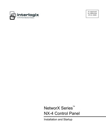
Installing the NX-595E into the enclosureInside the NetworX enclosure, several 2-holed insertion points have beenconstructed. This allows for either vertical or horizontal placement of the module.Note: Notice that the insertion points have two sizes of holes - a larger hole and asmaller hole.Figure 1: The black plastic PCB guides have slots along the straight edge wherethe PC Board will be seated. The curved side of the PCB guide fits into the largerhole. The smaller hole on the raised protrusion in the NetworX panel is for thescrew.Figure 2: Place the first black plastic PCB guide in the top insertion point with thePCB slot facing downward. It does not require force. Insert one of the screws intothe smaller hole to secure it in place. The second PCB guide should be positionedopposite of the first guide and placed in the lower insertion point, using the sameprocedures described above. Once mounted, screw it in securely.Figure 3: The PC board should slide freely in the slots of both guides.Figure 1Figure 2Figure 3Note: Record the 12 digit serial number of the NX-595E on the back of theUltraSync Quick Reference Guide that is included in the product packaging. Theserial number is located on NX-595E product label attached to the PCB. 2015 UTC Fire & Security Americas Corporation, Inc. All rights reserved.11
Wiring the NX-595ECaution: Remove all power (AC and battery) to the NetworX security systembefore proceeding. Failing to do so could result in possible damage to the product.Terminal descriptionsTerminalDescription1PosPositive terminal2Com3DataPanelBusCommon terminalData terminal on the NetworX panelstrd14 Z11 / 3 ZoneAdditional15 ComZonesCommon (-) return for Zoneloop16 Z22 / 4 Zone20 NC1Normally closed21 C1ndRelay 1thNormally open23 NC2Normally closed25 NO2Relay 23.7K Low zones6.9K High zonesThis relay can be controlledfrom the UltraSync applicationCommon22 NO124 C23.3K Single EOLsThis relay can be controlledfrom the UltraSync applicationCommonNormally open1. Connect the NX-595E's terminals POS, COM & DATA to the NetworX bus.2. Connect one end of an Ethernet cable to the RJ45/Ethernet connector on theNX-595E. Connect the other end of the Ethernet cable to an available Ethernetport on the Internet router. The router should automatically assign the NX-595Emodule an IP address when it is powered up.3. If you are utilizing the output relay or additional zone functionality of the NX595E, connect the wiring to the appropriate terminals. Additional instructionsregarding output relay and zone functionality are included this manual.4. Re-connect the power to the NetworX security system. You are now ready toconfigure the NX-595E.Note: In the unlikely event that the Internet router is not configured to automaticallyassign an IP address, you will have to manually assign an IP address and networksettings in the NX-595E. Instructions to manually assign the network settings areincluded in Appendix 1 at the end of this manual.12 2015 UTC Fire & Security Americas Corporation, Inc. All rights reserved.
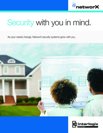
NX-595E Connector LayoutFigure 4Preparing the NX-595E for ConfigurationBefore you can configure the device, you must:1. Enroll the NX-595E in the NetworX panel.2. Default the NX-595E.3. Retrieve the IP address from the NX-595E.You can accomplish these three steps via any LCD (NX-148xx), Voice (NX-181xx)or touchscreen (NX-182xx) keypad. 2015 UTC Fire & Security Americas Corporation, Inc. All rights reserved.13
Enrolling, Defaulting and Retrieving the IPAddress for the NX-595EThe NX-595E is automatically set to device address 191 and programming iscarried out like all other NetworX modules.Default the NX-595E following these instructions depending on the type of keypadyou are using. When you exit program mode, the NX-595E will be automaticallyenrolled.Using a NX-181xx Voice keypadStep1.2.3.4.5.6.7.8.9.10.11.12.14Selects main menu - Option 0, Advanced systemconfiguration Enter your code, touch menu to exit.[?]-[?]-[?]-[?] Enter your 4 or 6 digit Programming codeTouch 1 for keypad configurationTouch 2 for panel and device configuration Touch 3 to configure service provider phonenumberTouch menu to exit.[2]Selects Panel and Device configurationa device number followed by enter SelectTouch menu to go back.[ 1 ][ 9 ][ 1 ]Connects to device 191 (NX-595E)[ENTER]Selected device 191 is connected. Select a Location number followed by enterTouch menu to go back.[ 9 ][ 1 ][ 0 ]Defaults the device, Note: only required once[ENTER][2][1]This keypad will announce the first number of the IP[Enter]addressThis keypad will announce the second number of the[MENU]IP addressThis keypad will announce the third number of the IP[MENU]addressThis keypad will announce the fourth number of the IP[MENU]address[MENU]Moves back to step 4, select a device numberMoves back to step 3, Advanced system configuration[MENU]selection.Exits from Advanced system configuration. (exiting[MENU]program mode automatically enrolls the NX-595E)[MENU]-[0] 2015 UTC Fire & Security Americas Corporation, Inc. All rights reserved.
Using a NX-182xx touch screen keypadStep1.[MENU]Press the Menu button2.[Settings]Press the Settings button3.[?]-[?]-[?]-[?] Enter your 4 or 6 digit Programming code4.[ Program]Press the Program button5.[ 1 ][ 9 ][ 1 ][ENTER]Connects to device 191 (NX-595E)6.[ 9 ][ 1 ][ 0 ][ENTER]7.[ 2 ][ 1 ][ENTER]NX-595E. Scroll through the segments with the [Exit]Press the Exit button. (exiting program modeautomatically enrolls the NX-595E)Defaults the device, Note: only required onceAccess location 21 to retrieve the IP address of the8.button and record the IP address (e.g. 192.168.1.2)Using a Standard Keypad (Icon or LCD)Step1.2.3.4.[*][8][?]-[?]-[?]-[?][1][9][1] - [#][9][1][0] - [#]Selects Panel and Device programmingEnter your 4 or 6 digit Programming codeConnects to device 191 (NX-595E)Defaults the device, Note: only required onceTo discover the IP address of the NX-595E (Press * to5.[2][1][#]scroll through each segment of the IP address. Recordthe IP address (e.g. 192.168.1.2)6.[Exit]Moves back to step 37.[Exit]Exits programming (exiting program modeautomatically enrolls the NX-595E) 2015 UTC Fire & Security Americas Corporation, Inc. All rights reserved.15
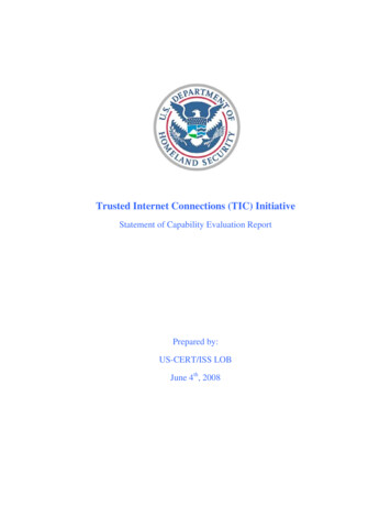
Configuring the NX-595EYou have two options to configure the device. A direct connection with a web browser on a computer or mobile device Via the UltraSync application on an Apple iOS or Android deviceNote: Before you can utilize the UltraSync application to configure the NX-595E,you must program in the Web Access Passcode in the Network Settings tab. It isrecommended that the initial configuration of the device be completed with a webbrowser.There is limited configuration capability with a connected keypad. Please seeAppendix 1 – Advanced Setup for keypad worksheets for more information.Configuring the NX-595E (Web browser or UltraSync)Note: Configuration of the NX-595E with a web browser and the UltraSyncapplication is virtually identical. The screenshots below show the Web browser viewwhen configuring the device. If you are using a computer, you can connect your computer to the same routerthat the NX-595E is connected to with an Ethernet cable. If you are using WiFi to access the network (e.g. with a tablet, WiFi enabledcomputer or smart phone), make sure the WiFi router is connected to the samenetwork that the NX-595E is connected to.Enter the IP address of your NX-595E into the web browser to access the NX-595E.This is the IP address that was retrieved above in the Enrolling, Defaulting andRetrieving the IP Address section of this document.Figure 5Note: The IP address that was retrieved from the device was most likely assignedby the network router. If the router or NX-595E is reset, power cycled, or a longperiod of time has expired since you retrieved the IP address, a new IP addressmight be assigned to the NX-595E. If the IP address you are using is not working,retrieve the IP address with the instruction in the Enrolling, Defaulting andRetrieving the IP Address section of this document. You do not need to perform thedefaulting portion of these instructions when retrieving the IP address.16 2015 UTC Fire & Security Americas Corporation, Inc. All rights reserved.
Sign in PageWhen successfully connected, the NX-595E will display the “Sign in” Page. Enterthe correct username/password combination to login. Default Installer Username:installer (username is case sensitive) Password:(enter the NetworX panel programming code)Notes:1. The password used to log into the NX-595E is the programming code thatresides in the NetworX panel.2. The Username used to log into the NX-595E is stored in the NX-595E. Thedefault installer name can be changed on the Feature Setup menu after youhave logged in.Note: Logging in as the installer will not allow programming of the NetworX panel.Main Menu (Accessed with Installer Credentials) 2015 UTC Fire & Security Americas Corporation, Inc. All rights reserved.17
Feature SetupEnable Zone Doubling: Allow the two onboard zones to double to four zones (notavailable on NX-4 panels). These zones cannot be used for 2-wire smokedetectors.Single EOL resistors3.3KLowerZoneN/AZone Doubled EOL resistorsN/A3.7KZoneHigherZoneN/A6.9KStart Zone: Used to enter the starting zone number of the additional zones on theNX-595E. Select from the drop down menu.Installer Name: Default installer name is installer and is case sensitive. This isthe username to sign in via a web browser or the UltraSync application.Service Number: The system service number will be announced at NX-181xxVoice keypads when a system fault is present. Your customer service telephonenumber is the recommended setting.GMT Offset Hours/Minutes: Sets local GMT (Greenwich Mean Time).DST Start / End month: Selects the month daylight savings begins and ends forthe particular installation region.DST Start / End week: – Selects which Sunday daylight savings begins and endsfor the particular installation region.Firmware, Hardware, Web version, Voice and Language: Displays the currentversions loaded on the connected NX-595E.18 2015 UTC Fire & Security Americas Corporation, Inc. All rights reserved.
Network SettingsMAC Address: Media Access Control address (MAC address) is a unique identifierassigned to most network interface cards by the manufacturer for identification.Host Name: Fixed as “NX595E.”Enable DHCP: When enabled, the NX-595E will automatically receive its IPaddress from the network router. If this segment is disabled, the NX-595E will needto have its IP address set manually. It is recommended that DHCP be enabled.Enable Ping: The “Ping” command is always functional while the NX-595E is inprogram mode. Disable this option to allow the NX-595E to ignore "ping"commands in normal operation. For security reasons it is recommended this optionbe disabled.Enable NTP Server Time Updates: The NX-595E will check its internal clock anduse the internet to compare it against GMT time. This is done every 15min and willupdate itself if the variance is greater than 3 minutes.Enable DLX900 Server: Allows remote configuration using DLX900 software.Disable to prevent DLX900 connections to the NX-595E. Enabled by default and forthe first 5 minutes after power up. Note that this option does not prevent DLX900connections to the panel via PSTN, disable this in panel programming if required.Enable Web Access: When enabled, email and IP reporting will function.Alternatively, if the Web Access Passcode is set to a non-zero value, email and IPreporting will function.IP Address: IP address of the NX-595E module. If Enable DHCP is unchecked,this field is editable and a static IP address can be assigned manually. 2015 UTC Fire & Security Americas Corporation, Inc. All rights reserved.19
Gateway: IP address of the gateway device (e.g. WiFi router, DSL or cablemodem). If Enable DHCP is unchecked, this field is editable and the IP address ofthe gateway can be assigned manually in the NX-595E.Subnet Mask: Subnet mask of the local area network (LAN). If Enable DHCP isunchecked, this field is editable and the subnet mask can be assigned manually.Primary DNS: IP address of the primary DNS server (editable if Enable DHCP isunchecked).Secondary DNS: IP address of the secondary DNS server (editable if EnableDHCP is unchecked).SSL Port: Not used.Web Access Passcode: This code allows the UltraSync iPhone and Androidapplications to connect to the security system, and enables email and IP reporting.A value of 00000000 disables UltraSync application support. Enter a unique WebAccess Passcode (eight numerical digits only) and click the Save Config button toenable UltraSync application support. Record the Web Access Passcode on theback of the UltraSync Quick Reference Guide.Web Access Server 1: This server address should not be changed. It enables theremote web access, UltraSync iPhone and Android applications and email services.Web Access Server 2: This ser
Connect the equipment into an outlet on a circuit different from that to which the receiver is connected. Consult the dealer or an experienced radio/TV technician for help. You may also find helpful the following booklet, prepared by the FCC: "How to Identify and Resolve Radio-TV Interference Problems." This