Transcription
Boot Mode Considerations: BIOS vs. UEFIAn overview of differences between UEFI Boot Mode and traditional BIOS Boot ModeDell EngineeringJune 2018
RevisionsDateDescriptionOctober 2017Initial releaseJune 2018Added DHCP Server PXE configuration details.The information in this publication is provided “as is.” Dell Inc. makes no representations or warranties of any kind with respect to the information in thispublication, and specifically disclaims implied warranties of merchantability or fitness for a particular purpose.Use, copying, and distribution of any software described in this publication requires an applicable software license.Copyright 2017 Dell Inc. or its subsidiaries. All Rights Reserved. Dell, EMC, and other trademarks are trademarks of Dell Inc. or its subsidiaries. Othertrademarks may be the property of their respective owners. Published in the USA [1/15/2020] [Deployment and Configuration Guide] [Document ID]Dell believes the information in this document is accurate as of its publication date. The information is subject to change without notice.2: BIOS vs. UEFI Doc ID 20444677 June 2018
Table of contentsRevisions.2Executive Summary .41Introduction .52Comparing UEFI and Traditional BIOS .6342.1Partitioning Scheme for Boot Media .62.2Handoff from BIOS to Operating System .62.3User Interfaces for Firmware .62.4Resource Allocation for Boot Device Firmware .7Features Requiring UEFI Boot Mode .83.1UEFI Secure Boot .83.2Boot to Non-Volatile Memory Express (NVMe) Devices .83.3Boot to Uniform Resource Identifier (URI) .8Configuration Settings for UEFI Boot Mode .94.1UEFI Boot Settings .94.2UEFI Boot from Local Media .124.3UEFI PXE Boot Configuration .124.3.1 PXE Client Configuration .134.3.2 PXE Server Configuration . Error! Bookmark not defined.4.4UEFI HTTP Boot Configuration (Boot from URI) .154.4.1 HTTP Boot Client Configuration .164.4.2 HTTP Boot Server Configuration .174.5UEFI iSCSI Boot Configuration .174.5.1 UEFI iSCSI Initiator Configuration .174.5.2 iSCSI Target Configuration.2154.6UEFI Secure Boot Configuration .214.7Integrated Device Firmware .21Technical support and resources .235.13Related resources .23: BIOS vs. UEFI Doc ID 20444677 June 2018
Executive SummaryDell EMC servers provide the option of using the traditional BIOS boot mode or UEFI boot mode. The bootmode determines how the system BIOS interacts with adapter card firmware and operating system software.Specific security features and boot mechanisms are available only when the system is configured for UEFIboot mode.This Dell EMC Deployment and Configuration Guide has two goals. First, it informs readers of the benefitsand shortcomings of the two boot modes, so they can choose the boot mode that is best for theirenvironment. Second, this paper provides an overview of the configuration needed to use UEFI boot mode. Itis assumed that the reader is familiar with the traditional BIOS boot mode, and likely has existinginfrastructure that uses BIOS boot mode. This paper outlines changes needed to support UEFI boot mode inan existing datacenter infrastructure.4: BIOS vs. UEFI Doc ID 20444677 June 2018
1IntroductionTraditionally, the system BIOS performs initialization, boot, system management, and configuration tasks. TheBIOS initializes the system’s processors, memory, bus controllers, and I/O devices. After initialization iscomplete, the BIOS passes control to operating system (OS) software. The OS loader uses basic servicesprovided by the system BIOS to locate and load OS modules into system memory. After booting the system,the BIOS and embedded management controllers execute system management algorithms, which monitorand optimize the condition of the underlying hardware. BIOS configuration settings enable fine-tuning of theperformance, power management, and reliability features of the system.The Unified Extensible Firmware Interface (UEFI) does not change the traditional purposes of the systemBIOS. To a large extent, a UEFI-compliant BIOS performs the same initialization, boot, configuration, andmanagement tasks as a traditional BIOS. However, UEFI does change the interfaces and data structures theBIOS uses to interact with I/O device firmware and operating system software. The primary intent of UEFI isto eliminate shortcomings in the traditional BIOS environment, enabling system firmware to continue scalingwith industry trends.Since 2010, Dell EMC has offered servers that support both the traditional BIOS boot mode and UEFI bootmode. However, the system administrator must choose the boot mode before deploying the server to itsoperating environment. This paper helps system administrators understand the implications of each bootmode. First, the paper explains the limitations of the traditional BIOS that UEFI resolves. Next, it describesfunctionality that is available in UEFI boot mode that is not available in BIOS boot mode. Finally, the paperprovides considerations for deploying a server in UEFI boot mode in the midst of a traditional datacenterinfrastructure.5: BIOS vs. UEFI Doc ID 20444677 June 2018
2Comparing UEFI and Traditional BIOSThis sections explains how UEFI corrects certain shortcomings in traditional BIOS implementations. The UEFIboot mode offers: 2.1Improved Partitioning scheme for boot mediao Support for media larger than 2 TBo Redundant partition tablesFlexible handoff from BIOS to OSConsolidated firmware user interfaceEnhanced resource allocation for boot device firmwarePartitioning Scheme for Boot MediaTraditional BIOS implementations use the Master Boot Record (MBR) scheme for partitioning boot media.Because it uses 32-bit addressing and 512-byte blocks, the MBR scheme limits the addressable storage inthe boot media to 2 TB. The MBR scheme also limits the number of partitions to four, and expects bootstrapcode to reside at specific locations in the media.UEFI defines an improved partitioning scheme known as a GUID Partition Table (GPT). The GPT schemeuses 64-bit addressing, so the boot media can be much larger than 2 TB. Each entry in the table is identifiedby a 128-bit Globally Unique Identifier (GUID), so the scheme supports a large number of partitions. Bootstrapcode is no longer required at fixed locations, and a backup partition table provides redundancy.2.2Handoff from BIOS to Operating SystemAfter performing system initialization, the BIOS attempts to transfer control to an operating system. TraditionalBIOS implementations maintain a prioritized list (“boot order”) of bootable media in the system, and attempt tolaunch boot software according to the list of media. For each entry in the list, the BIOS loads bootstrap codefrom a well-known location and passes control to it; if the attempt fails, the BIOS attempts subsequent entriesin the list.UEFI implementations also maintain a boot order, but each entry corresponds to an individual file instead ofan entire bootable medium. This scheme allows for one medium (such as a hard disk) to contain multiple bootorder entries (for example, multiple operating system loaders). Since each entry specifies the location of theboot file, UEFI also supports booting via Uniform Resource Identifiers (URIs).Unlike traditional BIOS implementations, all bootable files (executable bootstrap images) must be formattedaccording to the Portable Executable / Common Object File Format (PE/COFF). This requirement applies toany code executed by the BIOS, including device firmware (traditionally called “option ROMs”), pre-bootexecution environment (PXE) boot programs, and operating system loaders.2.3User Interfaces for FirmwareIn a traditional BIOS, each boot device provides a separate user interface for its configuration settings. Forexample, a network boot device provides one interface for PXE settings, and a storage controller provides a6: BIOS vs. UEFI Doc ID 20444677 June 2018
separate interface for hard-disk or RAID configuration. Most boot devices require a system reboot after anyfirmware change, so system configuration requires multiple boots.UEFI defines a shared user interface known as the Human Interface Infrastructure (HII). A user can configureall the firmware settings - including BIOS, onboard management controller, and boot devices – using a singleuser interface, without needing a reboot between changes for each device. HII also facilitates remoteconfiguration of all firmware settings via baseboard management controller interfaces.2.4Resource Allocation for Boot Device FirmwareTraditional BIOS implementations offer limited memory space for boot device firmware. Boot devices such asstorage controllers and network interface controllers require increasing amounts of memory to execute theirfirmware during the boot process. When a system contains multiple boot devices, a traditional BIOS may notallocate enough memory space for all of the device firmware to execute.UEFI eliminates this limitation by defining standard interfaces for memory management. In UEFI boot mode,boot devices use these interfaces to request memory space from the BIOS memory manager. When a systemcontains multiple boot devices, UEFI boot mode allocates memory on-demand for each device’s firmware.7: BIOS vs. UEFI Doc ID 20444677 June 2018
3Features Requiring UEFI Boot ModeAs UEFI grows in popularity, modern capabilities are implemented natively for UEFI Boot Mode instead ofBIOS Boot Mode. In Dell EMC servers, the following features are available only in UEFI Boot Mode: 3.1UEFI Secure BootBoot to Non-Volatile Memory Express (NVMe) devicesBoot to Uniform Resource Identifier (URI)UEFI Secure BootMost traditional BIOS implementations do not include mechanisms that verify the integrity of non-BIOS codemodules (such as I/O device firmware or operating system loaders). A traditional BIOS may offer protectionfor the non-volatile memory where the BIOS code is stored, as well as defenses against unauthorizedconfiguration changes. However, these implementations vary between vendors, and risks associated witheach implementation may be difficult to assess.UEFI defines a mechanism, named Secure Boot, which verifies the integrity of each pre-boot code moduleand allows only authorized code modules to execute. Users configure a Secure Boot Policy consisting ofX.509 certificates and hash values for both authorized and unauthorized entities. The system BIOS enforcesthis policy when determining whether to execute pre-boot software including I/O device firmware andoperating system loaders.For more information on Dell’s Secure Boot implementation and configuring the Secure Boot Policy, see thefollowing documents:Defining a Secure Boot Policy (Dell TechCenter)Secure Boot Management on 14G Dell EMC PowerEdge Servers (Dell TechCenter)3.2Boot to Non-Volatile Memory Express (NVMe) DevicesNon-Volatile Memory Express (NVMe) refers to an interface for accessing non-volatile storage connected byPCI Express. In Dell EMC PowerEdge servers (beginning with the 13th generation), the NVMe boot firmwareis developed by Dell as part of the BIOS firmware, instead of developed by individual NVMe device vendors.Dell EMC servers support booting to NVMe devices only when the server is configured for UEFI boot mode.3.3Boot to Uniform Resource Identifier (URI)A Uniform Resource Identifier (URI) is a character string that a system can use to access a file. For example,the URI “http://mydomain.org/img/bootimage.efi” indicates that a file named “bootimage.efi” can be accessedusing Hypertext Transfer Protocol (HTTP) at mydomain.org.The Dell EMC PowerEdge BIOS supports booting to URIs only in UEFI boot mode. The bootable URI mustuse the HTTP protocol. Also, the bootable URI must refer to an .EFI image (PE/COFF format). The Boot URIcan be configured in the System Setup utility or via remote management interfaces such as RACADM.8: BIOS vs. UEFI Doc ID 20444677 June 2018
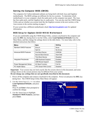
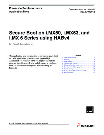
4Configuration Settings for UEFI Boot ModeThis section provides an overview of the configuration changes needed to operate a Dell EMC PowerEdgeserver in UEFI Boot Mode. It is assumed that the reader is familiar with the traditional BIOS boot mode, andlikely has existing infrastructure that uses BIOS boot mode.Unless otherwise noted, all configuration settings are accessible through integrated Dell Remote AccessController (iDRAC) interfaces such as RACADM, or locally through the System Setup utility. IDRAC interfacedocumentation can be found at http://www.delltechcenter.com/iDRAC. The System Setup utility is accessedby pressing F2 at the prompt shown during the system boot process.4.1UEFI Boot SettingsThe “Boot Mode” setting controls whether the system boots in the traditional BIOS mode or in UEFI mode. InSystem Setup, enter System BIOS Boot Settings and set Boot Mode to UEFI (see Figure 1). In RACADM,set the BootMode attribute to UEFI (see Figure 2).Figure 1 Setting Boot Mode in System Setup.9: BIOS vs. UEFI Doc ID 20444677 June 2018
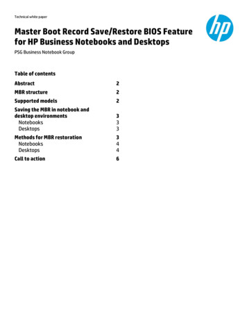
Figure 2 Setting Boot Mode in RACADM.When the system powers on with Boot Mode set to UEFI, the BIOS provides a list of available UEFI bootoptions. An administrator can view and edit the order of UEFI boot options. In System Setup, enter SystemBIOS Boot Settings UEFI Boot Settings (see Figure 3). Select UEFI Boot Sequence to edit the boot order.To disable specific boot options without changing the order, uncheck the desired options in the “Boot OptionEnable/Disable” section on this page.10: BIOS vs. UEFI Doc ID 20444677 June 2018
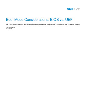
Figure 3 UEFI Boot Order Configuration.In RACADM, the “UefiBootSeq” attribute controls the UEFI Boot Order. Figure 4 shows an example of movingthe PXE boot device to the beginning of the boot order.11: BIOS vs. UEFI Doc ID 20444677 June 2018
Figure 4 UEFI Boot Order Configuration in RACADM.4.2UEFI Boot from Local MediaAs a general rule, operating systems installed in a traditional BIOS environment will not be bootable in UEFIboot mode. There are no reliable means for converting or upgrading traditional bootable media to a UEFIbootable form, other than re-installing the operating system when the BIOS is in UEFI boot mode.The boot mode must be configured before installing operating systems or other bootable software. Operatingsystem installers detect the current boot mode and provide tools for formatting the media accordingly. If theboot mode is UEFI, the installer will format the media using the GPT partitioning scheme. If the boot mode isBIOS, the installer uses the traditional MBR scheme. Operating systems also specify different boot loaders forthe two boot modes.4.3UEFI PXE Boot ConfigurationPXE is used to execute an operating system’s bootstrap program using a network connection. The PXE Clientsends a DHCP request with PXE specific options. The DHCP server response contains the NetworkBootstrap Program (NBP) filename and a list of TFTP boot servers. The PXE client downloads the NBP andthen executes it to complete the boot process.These are the primary differences between UEFI PXE and Legacy PXE: 12In UEFI boot mode the Network Bootstrap Program (NBP) must be a UEFI bootable image (PE/COFFformat).If UEFI PXE Boot is being used to install an OS, that OS will be installed in UEFI boot mode. If theboot mode is changed later, the OS must be re-installed in the new boot mode.If a chainloader like iPXE is used it can take advantage of the Universal Network Device Interface(UNDI) embedded in the NIC to support network adapters that would not be supported in legacymode.Because of the additional structure and security of UEFI, it will take a little longer to load the NBP.Legacy PXE firmware (option ROMs) on NICs may support options beyond PXE like IPv4/IPv6 HTTPboot and iSCSI boot. In UEFI boot mode, equivalent functionality is available through HTTP boot and: BIOS vs. UEFI Doc ID 20444677 June 2018
iSCSI boot configuration (see the UEFI HTTP boot and UEFI iSCSI boot sections in this paper fordetails).Minimal changes are required for the PXE server and PXE client when transitioning from BIOS boot mode toUEFI boot mode. The following sections describe these changes.4.3.1PXE Server ConfigurationPXE server setup involves configuration of the DHCP server and boot server (a.k.a. TFTP server).In UEFI boot mode the Network Bootstrap Program (NBP) must be a UEFI bootable image (PE/COFFformat). For Linux environments, UEFI-capable NBPs include ELILO, grub2, and syslinux. Windowsenvironments (Windows Server 2012 and later) use bootmgfw.efi. Alternatively, Windows DeploymentServices (WDS) offers PXE server configuration capabilities for UEFI-based PXE clients.4.3.2DHCP Server Configuration for UEFI PXETo support both legacy PXE and UEFI PXE in the same network, the DHCP server must supply differentNBPs based on the Architecture type (RFC 4578) in the client’s DHCP request. If the client sendsArchitecture type 0 (“Intel x86 PC”) the system is in legacy boot mode. If it sends type 6, it is in UEFI 32-bitboot mode, but if it sends type 7, 8 or 9 it is in UEFI 64-bit boot mode. The architecture type will be sent inOption 93 and as part of the string in Option 60 (“Vendor class identifier”). The reason it is included in bothoptions is backwards compatibility with older DHCP servers that do not support Option 93. The following isfrom a Wireshark capture of a PXE boot DHCP Discover:The following is an example of Linux DHCP server configuration that replies with different NBP files based onthe Architecture type. Note that the Architecture type is encoded in the first 20 characters of the vendor classidentifier:subnet { class "UEFI64-7" {match if substring(optionfilename "ipxe.efi";}class "UEFI64-8" {match if substring(optionfilename "ipxe.efi";}class "UEFI64-9" {match if substring(optionfilename "ipxe.efi";}class "Legacy" {match if substring(option13vendor-class-identifier, 0, 20) "PXEClient:Arch:00007";vendor-class-identifier, 0, 20) "PXEClient:Arch:00008";vendor-class-identifier, 0, 20) "PXEClient:Arch:00009";vendor-class-identifier, 0, 20) "PXEClient:Arch:00000";: BIOS vs. UEFI Doc ID 20444677 June 2018
filename "undionly.kkpxe";}}For detailed information on how to configure your DHCP server please consult the user’s guide for the DHCPserver.NOTE: Depending on the DHCP server configuration, the client may need to be configured for UEFI HTTPboot or UEFI iSCSI boot instead of PXE boot. If your current legacy boot DHCP server configuration containsan option 67 (filename) that is a URL instead of a simple filename, you need to configure the client UEFIHTTP boot settings instead of PXE boot. If you are using DHCPv6 option 59 (bootfile URL) in legacy modeyou need to configure client UEFI HTTP boot settings instead of PXE boot. If you are using Option 17(RootPath) you need to configure client UEFI iSCSI boot settings instead of PXE boot. See the UEFI HTTPboot and UEFI iSCSI boot sections in this paper for details.4.3.3PXE Client ConfigurationAs with other system settings, the PXE client configuration settings are accessible through integrated DellRemote Access Controller (iDRAC) interfaces such as RACADM, or locally through the System Setup utility.In BIOS boot mode, individual network devices provide the PXE settings in System Setup Device Settings.However, in UEFI boot mode, PXE settings are configured in the BIOS pages (System Setup System BIOS Network Settings PXE Device Settings). See Figure 5. The “Network Settings” option in the System BIOSpage is available only in UEFI boot mode.14: BIOS vs. UEFI Doc ID 20444677 June 2018
Figure 5 UEFI PXE boot Configuration.The parameters to be configured in this page are: 4.4Interface: the network interface in the PXE client to configure for PXE boot;Protocol: the Internet Protocol that will be used for PXE boot (IPv4 or IPv6);VLAN: ID and Priority for Virtual LAN if enabled.UEFI HTTP Boot Configuration (Boot from URI)UEFI HTTP boot is supported beginning with Dell PowerEdge 14G systems. The system that provides theNetwork Bootstrap Program (NBP) is known as the “HTTP boot server.” The “HTTP boot client” downloadsand executes the NBP to complete the boot process.15: BIOS vs. UEFI Doc ID 20444677 June 2018
The principle for HTTP boot is similar to PXE boot, except that HTTP boot uses HTTP (rather than TFTP) totransfer the NBP.4.4.1HTTP Boot Client ConfigurationAs with other system settings, the HTTP boot client configuration settings are accessible through integratedDell Remote Access Controller (iDRAC) interfaces such as RACADM, or locally through the System Setuputility.As shown in Figure 6, the UEFI HTTP Boot configuration page is found under System Setup System BIOS Network Settings HTTP Device Settings. The settings are similar to PXE settings with the addition of the“URI” setting, which specifies the location of the bootstrap program. The URI must use the HTTP protocol,and must specify the name of the bootstrap program (for example, http://mydomain.org/img/bootimage.efi).NOTE: If the “URI” setting is blank, the system will try to obtain the URI from the DHCP server (Option 67 Bootfile Name for DHCPv4; Option 59 - Bootfile Url for DHCPv6).HTTP Boot is supported only in UEFI boot mode. Also, the “Network Settings” option in the System BIOSpage is available only in UEFI boot mode.Figure 6 UEFI PXE boot Configuration.16: BIOS vs. UEFI Doc ID 20444677 June 2018
4.4.2HTTP Boot Server ConfigurationThe HTTP boot server is composed of two major parts: DHCP server and HTTP server. A domain namesystem (DNS) server is necessary as well if the URI specifies the domain name instead of the IP address.The bootstrap program provided by the HTTP boot server must be a UEFI bootable image (PE/COFF format).For Linux environments, UEFI-capable bootstrap programs include ELILO, grub2, and syslinux. Windowsenvironments (Windows Server 2012 and later) use bootmgfw.efi.4.5UEFI iSCSI Boot ConfigurationUEFI iSCSI Boot enables booting a system to a boot image located on a network-attached system. Thenetwork-attached system with the boot image is known as the “target.” The other system, the “initiator,” usesblock transactions (similar to the way a hard-disk controller accesses a local hard-disk drive) to access thebootable software stored on the network-attached target.Minimal changes are required for the iSCSI initiator and iSCSI target when transitioning from BIOS boot modeto UEFI boot mode. The following sections describe these changes.4.5.1UEFI iSCSI Initiator ConfigurationAs with other system settings, the UEFI iSCSI configuration settings are accessible through integrated DellRemote Access Controller (iDRAC) interfaces such as RACADM, or locally through the System Setup utility.In BIOS boot mode, individual network devices provide the iSCSI settings in System Setup Device Settings.However, in UEFI boot mode, iSCSI settings are configured in the BIOS pages (System Setup SystemBIOS Network Settings UEFI iSCSI Settings). See Figure 7. The initiator name is configured on this page;this is the unique name (in IQN format) for the iSCSI initiator. The “Network Settings” option in the SystemBIOS page is available only in UEFI boot mode.There are two iSCSI logical devices that can be configured for iSCSI boot. Each logical device appears as aseparate entry in the UEFI boot order. When an iSCSI logical device is enabled, its settings are available in itsiSCSI Device Settings menu. Figures 8 and 9 show the contents of the iSCSI Device Settings menu.17: BIOS vs. UEFI Doc ID 20444677 June 2018
Figure 7 UEFI iSCSI boot Initiator Name Configuration18: BIOS vs. UEFI Doc ID 20444677 June 2018
Figure 8 UEFI iSCSI boot Configuration.19: BIOS vs. UEFI Doc ID 20444677 June 2018
Figure 9 UEFI iSCSI boot Configuration (cont’d).The parameters to be configured for an iSCSI logical device are: 20Interface: the network interface in system to be configured for PXE boot;Protocol: the Internet Protocol that will be used for PXE boot (IPv4 Vs IPv6);VLAN parameters: VLAN ID and Priority Virtual LAN if enabled;TCP parameters: Retry Count and Timeout to manage TCP handshake retries and timeout condition;iSCSI Initiator parameters: if set DHCP to Disabled, iSCSI initiator parameter fields (IP Address,Subnet Mask and Gateway) will need to be filled out;iSCSI Target parameters: if set Target info via DHCP to Disabled, iSCSI target parameter fields(Target Name, IP Address, Port and Lun) will need to be filled out;ISID: set the initiator session identifier;Authentication parameters: CHAP Type, CHAP Name/Secret and Reverse CHAP Name/Secret fieldsare used for authentication purposes.: BIOS vs. UEFI Doc ID 20444677 June 2018
4.5.2iSCSI Target ConfigurationThe difference between iSCSI target configurations for UEFI and BIOS boot modes is the format of thebootable image on the target. In UEFI boot mode, the image must be a UEFI bootable image. iSCSI targetconfiguration steps for Windows and Linux can be found on their respective official websites.4.6UEFI Secure Boot ConfigurationThere are three primary settings involved in configuring UEFI Secure Boot. All three settings are available inBIOS Setup (System Setup System BIOS System Security) and iDRAC interfaces such as RACADM. TheBoot Mode must be set to UEFI; otherwise these settings are not configurable. Secure Boot is not availablewhen the Boot Mode is set to BIOS.To use UEFI Secure Boot, set the “Secure Boot” setting to “Enabled”, the “Secure Boot Policy” setting to“Standard”, and the “Secure Boot Mode” setting to “Deployed”. This configuration causes the BIOS to verifypre-boot code modules (such as adapter firmware and OS loaders) against an industry-standard set ofcertificates and hashes. The BIOS will execute only those modules signed by third parties trusted by Dell.The first setting (Secure Boot) instructs the BIOS whether to perform integrity and authorization checks onpre-boot code modules. When this setting is set to “Enabled” the BIOS enforces the Secure Boot policy foreach code module that is loaded during the boot process. When this setting is set to “Disabled” the BIOSloads code modules without performing integrity and authorization checks.The second setting (Secure Boot Policy) tells the BIOS which Secure Boot policy to enforce. When thissetting is set to “Standard” the BIOS uses an industry-standard set of certificates and hash values thatauthorize common operating systems and I/O adapter firmware. The Standard policy applies to a majority ofserver deployment environments. (The
After performing system initialization, the BIOS attempts to transfer control to an operating system. Traditional BIOS implementations maintain a prioritized list ("boot order") of bootable media in the system, and attempt to launch boot software according to the list of media. For each entry in the list, the BIOS loads bootstrap code