Transcription
Freescale SemiconductorApplication NoteDocument Number: AN4581Rev. 0, 09/2012Secure Boot on i.MX50, i.MX53, andi.MX 6 Series using HABv4byFreescale Semiconductor, Inc.This application note explains how to perform a secure booton i.MX applications processors that support HighAssurance Boot version 4 (HABv4). It provides steps togenerate signed images. It also includes steps to configurethe IC to run securely using tools provided freely byFreescale. 2012 Freescale Semiconductor, Inc. All rights reserved.1.2.3.4.5.6.7.8.9.ContentsAbout this Document . . . . . . . . . . . . . . . . . . . . . . . . . .2Overview . . . . . . . . . . . . . . . . . . . . . . . . . . . . . . . . . . . .5Code Signing . . . . . . . . . . . . . . . . . . . . . . . . . . . . . . . . .9Signed U-Boot Example . . . . . . . . . . . . . . . . . . . . . . .17Managing Electrical Fuses . . . . . . . . . . . . . . . . . . . . .19Development and Debugging Tips . . . . . . . . . . . . . . .27Troubleshooting . . . . . . . . . . . . . . . . . . . . . . . . . . . . .35U-Boot Modified Source Code and CSF . . . . . . . . . .36Revision History . . . . . . . . . . . . . . . . . . . . . . . . . . . . .42
About this Document11.1About this DocumentPurposeExecuting trusted and authentic code on an applications processor starts with secure boot provided by theon chip boot ROM. The i.MX family of applications processors provides this capability with the HABcomponent of the on-chip ROM. The HAB enables the ROM to authenticate software, which executesimmediately after ROM, by using digital signatures. This software is usually a bootloader.The HAB provides a mechanism to establish a root of trust for the remaining software components andestablishes a secure state on i.MX ICs that have secure state machine support in hardware.The purpose of this application note is to explain how to perform a secure boot on i.MX applicationsprocessors that include HABv4. It tells the user how to generate signed images and configure the IC to runsecurely using tools provided freely by Freescale.1.2ScopeIn this document, a practical example based on u-boot is used to illustrate the construction of a secureimage, in addition to configuring the device to run securely. Extending the secure boot chain past the initialstage is also possible with HAB, but that is beyond the scope of this document.This document answers all the following questions: What components are required?— A boot image— A set of signing keys and certificates— Resulting digital signatures How is each of these different components generated? How are all these components assembled to create a signed image?NOTEThis document covers secure boot on the following i.MX processors usingHABv4: i.MX50, i.MX53, and i.MX 6 Series. Secure boot features for otherprocessors, such as i.MX25, i.MX35, and i.MX51, which use HABv3, aredocumented in Secure Boot on i.MX25, i.MX35, and i.MX51 using HAB3application note (AN4547).NOTESecure boot features for i.MX28 are documented in Secure Boot withi.MX28 HAB v4 application note (AN4555). i.MX28 supports HABv4 butits boot architecture is significantly different from other processors in thei.MX family.NOTESecure boot using HAB is no longer supported on i.MX27 and i.MX31.Secure Boot on i.MX50, i.MX53, and i.MX 6 Series using HABv4, Rev. 02Freescale Semiconductor
About this Document1.3AudienceThis document is intended for those who: Need an architectural-level technical understanding of how HAB works in the boot sequence Need to design signed software images to be used with a HAB-enabled processorIt is assumed that the reader is familiar with the basics of digital signatures and public key certificates.1.4Definitions, Acronyms, and AbbreviationsDefinitions of the terms and acronyms used in this document are as follows: CA: Certificate Authority, the holder of a private key used to certify public keys. CAAM: Cryptographic Acceleration and Assurance Module, an accelerator for encryption, streamcipher, and hashing algorithms, with a random number generator and run time integrity checker. CMS: Cryptographic Message Syntax, a general format for data that may have cryptographyapplied to it, such as digital signatures and digital envelopes. HAB uses the CMS as a containerholding PKCS#1 signatures. CSF: Command Sequence File, a binary data structure interpreted by the HAB to guideauthentication operations. CST: Code Signing Tool, an application running on a build host to generate a CSF and associateddigital signatures. DCD: Device Configuration Data, a binary table used by the ROM code to configure the device atearly boot stage. DCP: Data co-processor, an accelerator for AES encryption and SHA hashing algorithms. HAB: High Assurance Boot, a software library executed in internal ROM on the Freescaleprocessor at boot time which, among other things, authenticates software in external memory byverifying digital signatures in accordance with a CSF. This document is strictly limited toprocessors running HABv4. IVT: Image Vector Table. OS: Operating System. OTP: One-Time Programmable. OTP hardware includes masked ROM, and electricallyprogrammable fuses (eFuses). PKCS#1: Standard specifying the use of the RSA algorithm. PKI: Public Key Infrastructure, a hierarchy of public key certificates in which each certificate(except the root certificate) can be verified using the public key above it. RTIC: Run-Time Integrity Checker, a SHA256 hash accelerator that ensures of software integrityduring run time. RSA: Public key cryptography algorithm developed by Rivest, Shamir, and Adleman. SA: Signature Authority, the holder of a private key used to sign software components. SAHARA: Symmetric / Asymmetric Hashing and Random Accelerator, a cryptographicaccelerator (including hash acceleration) found on some processors.Secure Boot on i.MX50, i.MX53, and i.MX 6 Series using HABv4, Rev. 0Freescale Semiconductor3
About this Document 1.5 SDP: Serial Download Protocol, also called UART/USB Serial Download Mode. This allows codeprovisioning through UART or USB during production and development phases.SRK: Super Root Key, an RSA key pair which forms the start of the boot-time authentication chain.The hash of the SRK public key is embedded in the processor using OTP hardware. The SRKprivate key is held by the CA. Unless explicitly noted, SRK in this document refers to the publickey only.UID: Unique Identifier, a unique value (such as, a serial number) assigned to each processor duringfabrication.XIP: Execute-In-Place, refers to a software image that is executed directly from its non-volatilestorage location rather than first being copied to volatile memory.Referencesi.MX50 Reference Manual, i.MX53 Reference Manual, and i.MX 6Dual/6Quad Reference Manual.i.MX53 Security Reference Manual, i.MX 6Dual/6Quad Security Reference Manual, and i.MX6Solo/6DualLite Security Reference Manual.HAB CST User Guide available in the Code Signing Tool package downloadable on freescale.com.Search for IMX CST TOOL.Secure Boot on i.MX50, i.MX53, and i.MX 6 Series using HABv4, Rev. 04Freescale Semiconductor
Overview2OverviewThis section gives a technical overview of HAB, and provides the background needed for understandingthe use cases and processes described in later sections.2.1Boot ROM Code and HAB LibraryIn order to design a correctly signed boot image, it is necessary to understand both the components thatmake up the HAB and the basic boot-time authentication process. This section gives an architectural-leveloverview of these elements.The boot ROM is the first software executed after reset, and it controls the initial phase of the boot process.The boot ROM uses the HAB library to authenticate the boot image in external memory, prior to itsexecution. Based on pin or fuse settings, the boot ROM executes different boot modes to locate, load, andexecute the boot image from various boot peripherals (for example, NAND flash, SD/MMC card, Harddrive, serial EEPROM/flash, USB recovery mode, and so on). To ensure a secure boot, correct executionof the boot ROM must be guaranteed. To achieve this, the integrity of the boot ROM is protected by placingit inside a masked processor internal ROM that cannot be modified. Execution of the boot ROM is alsoprotected by disabling external boot modes, unauthorized JTAG control, and interrupts.The HAB library, embedded in the processor ROM, contains functions to authenticate an image as well asinitialize and test security hardware. The same library functions can be called from later boot stages toextend the secure boot chain past the stage immediately after the boot ROM.The areas of an image that HAB verifies are completely customizable through a series of commands thatare interpreted by HAB. These are known as Command Sequence File (CSF) commands that define thememory locations a digital signature covers, which keys to verify the signature with, and so on. All CSFprocessing, including PKI operations and cryptographic hash and digital signature verification, isperformed within the HAB library. Where available, the HAB library makes use of on-board hardwareaccelerators (such as, RTIC, CAAM, or DCP) to improve boot performance. HABv4 makes exclusive useof the RSA algorithm, with all signatures following the CMS format, and all certificates following theX509v3 format.For more details, see the reference manual of the processor being used, in addition to the HAB CST UserGuide listed in Section 1.5, “References.”Secure Boot on i.MX50, i.MX53, and i.MX 6 Series using HABv4, Rev. 0Freescale Semiconductor5
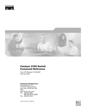
Overview2.2Boot FlowThe boot ROM execution flow for i.MX applications processors that includes HABv4 is shown in Figure 1.“Process CSF with HAB” is the point in the flow where digital signatures across an image are verified.When configured for secure operation, the boot ROM on i.MX devices will not allow unauthenticated codeto execute. Any signature failures or security violations forces the boot ROM to enter the Serial DownloadProtocol (SDP), which can be used to provide a new signed image to the boot device. Note that whenconfigured for secure operation, even images downloaded through SDP must be properly signed beforebeing executed.Figure 1. Secure Boot Flow from DeviceSecure Boot on i.MX50, i.MX53, and i.MX 6 Series using HABv4, Rev. 06Freescale Semiconductor
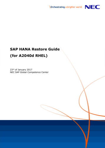
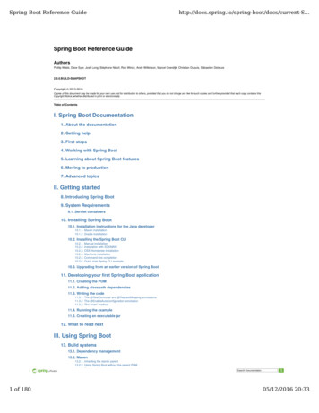
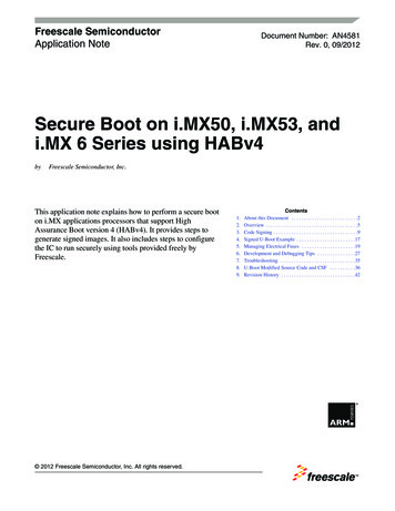
Overview2.3HAB Public Key InfrastructureHAB authentication is based on public key cryptography using the RSA algorithm in which image data issigned offline using a series of private keys. The resulting signed image data is then verified on i.MXprocessor using the corresponding public keys. This key structure is known as a PKI tree.Figure 2 gives an example of a typical PKI tree that is generated by the Freescale Code Signing Tools.Figure 2. HABv4 Enabled Devices Typical PKI TreeFor further information on the PKI tree used for HABv4, see the HAB CST User Guide mentioned inSection 1.5, “References.” The details of digital signature authentication with the RSA algorithm arebeyond the scope of this document.The authentication steps performed by HAB occur in stages that are shown in Figure 3.Figure 3. HABv4 Enabled Devices Detailed PKI TreeIn i.MX processors, the authentication begins with establishing a root of trust with the SRK. HAB doesthis by computing a cryptographic hash of the SRK table and comparing the result with a pre-computedSecure Boot on i.MX50, i.MX53, and i.MX 6 Series using HABv4, Rev. 0Freescale Semiconductor7
Overviewhash that is provisioned in OTP fuses. This ensures that the integrity of the SRK table included in the imageis intact. This is the beginning of the authentication chain in which the SRK is used to authenticate otherkeys which exist in the form of X509 certificates. For details on what is SRK table and how to generate it,see the HAB CST User Guide.The arrows in Figure 3 show the authentication flow. For example, the SRK key is used to authenticateboth the CSF and the image keys.There are several important features to note. First, each key can certify multiple instances of the objectsbeneath it. For example, a single SRK can certify multiple CSF keys, and a single image key can certifymultiple images. Nevertheless, the CSF key can only authenticate the CSF. The objects closer to the rootof the PKI have greater impact if compromised, and require more protection. To some extent, this is offeredby the CST tool, but it is important that the CST user adopt appropriate policies and processes. Forexample, a poorly planned CSF can open the way for malicious applications to be loaded in place of theauthentic one. It is, therefore, prudent to plan the CSF so it does not need to change with every new versionof the application, and restrict the group authorized to sign CSFs to a relatively small number of people.Secondly, the authentication of an image key through the CSF may be a little different to the other linksshown in Figure 3. In order to provide better key separation, an image key may be bound to the CSF, usinga hash fingerprint embedded in the CSF. This means that it would not be possible to use the CSF with otherimage keys, even if they have been certified by the same SRK. Addition of the hash is optional and isdependent on whether the Hash Algorithm argument is present in the Install Key command. See the InstallKey command documentation in the HAB CST User Guide for further details.Secure Boot on i.MX50, i.MX53, and i.MX 6 Series using HABv4, Rev. 08Freescale Semiconductor
Code Signing33.1Code SigningIdentifying the Required ComponentsA secure boot requires a number of data components to be added to an image. This includes keys,certificates, signatures, IC configuration data, and CSF data.When performing a secure boot on i.MX boot ROM and HAB, the following data components are requiredto be defined in the image: Image Vector Table: A table of pointers used by the boot ROM to locate other required datacomponents. Boot data structure: A simple structure indicating where to load the boot image and specifying thesize of the boot image. Device Configuration Data (DCD): A list of registers that the ROM will program with the provideddata to perform an early initialization of the system. DCD is typically used to initialize theSDRAM. Command Sequence File (CSF) and associated data: A block of data containing the commands thatthe HAB will execute during boot, as well as the associated certificates and signatures HAB usesto verify an image.3.1.1Image Vector Table and Boot DataThe Image Vector Table (IVT) is a mandatory part of the boot image, and its structure could be defined asfollows:typedef struct{uint32 tuint32 tuint32 tuint32 tboot data tuint32 tuint32 tuint32 t} image vector table t;header;*entry;reserved1;*dcd;*boot data;*self;*csf;reserved2;Where: uint32 t: A type representing a 32-bit unsigned integer. header: Header identifying the type of data structure (0xD1), its size (0x0020), and HAB version(such as, 0x40). For example, i.MX53 uses D100 2040h. *entry: Absolute address of the first instruction to be executed from the image. reserved1: Reserved and should be zero. *dcd: Absolute address of the image Device Configuration Table (DCD). The DCD is optional, sothis field may be set to NULL, if no DCD is required.Secure Boot on i.MX50, i.MX53, and i.MX 6 Series using HABv4, Rev. 0Freescale Semiconductor9
Code Signing *boot data: Absoluteaddress of the Boot Data structure.*self: Absolute address of the IVT. Used internally by the ROM.*csf: Absolute address of the Command Sequence File (CSF) used by the HAB library. This fieldmust be set to NULL, if not performing a secure boot.reserved2: Reserved and should be zero.The Boot Data is an associated structure that indicates where to load the boot image and that specifies thesize of the boot image. It is defined as follows:typedef struct{uint32 tuint32 tuint32 t} boot data t;*start;length;plugin flag;Where: *start: Absolute address of the boot image. Typically, somewhere in the SDRAM. length: Size of the boot image to copy from the boot device to address *start. plugin flag: Reserved and must be zero.The IVT is a block of data that must reside at a specific address that depends on the boot device, and isspecified in the System Boot chapter of the reference manual.3.1.2Device Configuration DataThe main purpose of the DCD is to allow peripherals to be configured for optimal performance duringapplication authentication. A second purpose is to allow memory controllers to be configured beforeloading the application from non-volatile storage to its run-time location in external RAM. Since DCDprocessing occurs prior to authentication, the scope of valid DCD operations is strictly limited to certaincontrollers (for example, clock, memories, and so on).For more information, see the System Boot chapter of the reference manual.NOTESome bootloaders use plug-in code to perform the device configuration;however, this method must not be used for a secure boot. The DCD methodmust be used instead, which provides the highest level of security andperformance at boot.3.1.3Command Sequence FileThe CSF is a binary data structure interpreted by the HAB library to guide the authentication process. Itcontains records that determine: The PKI tree to be used in authentication operations. The physical memory regions to be authenticated, along with the authentication method andreferenced data.Secure Boot on i.MX50, i.MX53, and i.MX 6 Series using HABv4, Rev. 010Freescale Semiconductor
Code Signing Device configuration operations.Device configuration operations in the CSF are separate from those in the DCD. The important differencebetween the two is that DCD may configure only a limited range of peripherals (since DCD processing isperformed prior to authentication) whereas device configuration operations within the CSF areunconstrained. This is because CSF commands are authenticated before they are executed.With HAB, multiple non-contiguous regions of physical memory can be covered with a single digitalsignature. The maximum number of regions, which is limited by the hash computation engine used or itsdriver in ROM, can be defined as follows: When using RTIC for the hash computation of digital signature verification, a maximum of two (2)non-contiguous blocks are supported. When using SAHARA for the hash computation of digital signature verification, a maximum oftwelve (12) non-contiguous blocks are supported. When using CAAM for the hash computation of digital signature verification, a maximum of eight(8) non-contiguous blocks are supported. When using DCP for the hash computation of digital signature verification, a maximum of six (6)non-contiguous blocks are supported. Note that all blocks except the last one must be a multiple of64 bytes in length. The last data block may be of an arbitrary length.If software implementation is used for hash computations included in HAB, then, there is no maximumlimit.3.23.2.1Laying Out a Boot ImageCommon Image LayoutWhen performing a secure boot on an i.MX processor based on HABv4, the image must contain a correctlyformatted image vector table with a valid header and pointers, and a DCD table.The first step of the boot process is to copy 1 kB, 2 kB, or 4 kB from the boot device into the OCRAM.The size copied depends on the boot device. This does not apply to a parallel NOR flash that uses XIP. Seethe System Boot chapter of the reference manual for more details.At power up, the boot ROM expects a valid IVT that is placed at a known offset. The ROM code starts byextracting the pointer to the DCD table *dcd, and the DCD commands are processed. Note that when theprocessor is in Closed configuration, only certain memory regions are programmable by the DCD. Thecomplete list is provided in the System Boot chapter of the reference manual.If there are no errors to this point, then, the ROM reads the boot data information, and copies the specifiedlength to the address *start.Note that all the pointers included in the flash header are with respect to the final destination in memory*start.At this stage, the rest of the boot process diverges depending on the security configuration: Open or Closedconfiguration, which is determined by the SEC CONFIG fuse field.Secure Boot on i.MX50, i.MX53, and i.MX 6 Series using HABv4, Rev. 0Freescale Semiconductor11
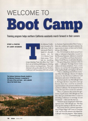
Code Signing3.2.2Non-Secure Boot Image LayoutWhen performing a non-secure boot with the SEC CONFIG fuse field set to Open, providing the CSF dataas part of the image is optional. If CSF data is not provided, the *csf field of the IVT must be set to NULL.Regardless of whether a valid CSF present or not, HAB will attempt to authenticate the image performingthe same steps as it would do for a secure boot in Closed configuration. If authentication fails, then, HABwill log events that can later be used for debugging purpose, and will continue execution of the normalboot flow. Eventually, ROM code will jump to the image pointed by *entry.Note that when SEC CONFIG fuse field is set to Open, all HAB failures are considered to be non-fataland the boot process is allowed to continue. The Open configuration should also be used for developmentpurposes of secure products, where CSFs and other data components for secure boot can be debugged. TheOpen configuration is the end configuration for non-secure products.Figure 4. Typical Memory Layout of an Unsigned ImageInitially a small part (1 kB / 2 kB / 4 kB) of the boot code is read, so the IVT, DCD, and boot data must belocated in that area.The size of the free region and the IVT offset vary with the boot device. See the System Boot chapter ofthe reference manual for more details.Secure Boot on i.MX50, i.MX53, and i.MX 6 Series using HABv4, Rev. 012Freescale Semiconductor
Code Signing3.2.3Secure Boot Image LayoutThe SEC CONFIG fuse field tells HAB whether or not to boot the device securely. If this field is set toClosed, the i.MX processor will only allow a properly signed image to execute. In Closed configuration,the CSF data component is mandatory and must be included in the image, along with valid pointers in theIVT structure. This is true regardless of which boot device is chosen, including USB recovery mode.The first step performed by HAB when performing a secure boot is to install the SRK. It is important tohave the SRK tied to the processor to avoid it being replaced by another non-trusted key. Therefore, duringthe installation of the SRK, the ROM computes a SHA-256 hash of the SRK table attached to the binaryCSF data. The result is compared to the reference value provisioned into the OTP fuses during productmanufacturing.Following are the principal steps (not necessarily in order) involved in processing the CSF: Verify the CSF key certificate using the SRK. Verify the CSF signature using the CSF key. Verify image key certificates using the SRK. Verify image signature(s) using the image keys. Perform any device configuration operations specified in the CSF.Note that not all steps apply to every CSF.Secure Boot on i.MX50, i.MX53, and i.MX 6 Series using HABv4, Rev. 0Freescale Semiconductor13
Code SigningFigure 5. Typical Memory Layout of a Signed ImageInitially a small part (1 kB / 2 kB / 4 kB) of the boot code is read, so the IVT, DCD, and boot data must belocated in that area.The size of the free region and the IVT offset vary with the boot device. See the System Boot chapter ofthe reference manual for more details.NOTEThe HAB requires that the IVT, initial byte of boot data, DCD table, and thefirst word of the image all must be covered by a digital signature.Secure Boot on i.MX50, i.MX53, and i.MX 6 Series using HABv4, Rev. 014Freescale Semiconductor
Code Signing3.33.3.1Generating CSF Data and SRK TableGenerating Command Sequence File (CSF) DataThe CSF contains all the commands that the ROM executes during the secure boot. These commandsinstruct HAB on which memory areas of the image to authenticate, which keys to install and use, what datato write to a particular register, and so on. In addition, the necessary certificates and signatures involved inthe verification of the image, as well as the SRK table, are attached to the CST.The first CSF in the boot sequence must contain an Install Key command to install the SRK table prior toCSF key installation. It should also contain an Install Key command to install the CSF key prior to CSFauthentication. Every CSF must contain an Authenticate Data command to authenticate the CSF contentsusing the CSF key.To facilitate well-formed CSF generation, Freescale provides Code Signing Tool (IMX CST TOOL) as areference for creating the CSF data. The package with the software executable and the associateddocumentation is available on the Freescale website as mentioned in Section 1.5, “References.”The binary output from the CST consists of the following components: CSF: Commands interpreted by HAB SRK table and corresponding fuse pattern Public key certificates CSF signature One or more image signaturesNOTEPrior to continuing with examples described in this application note, see theHAB CST User Guide, available in the above mentioned package, to get abetter understanding of the code signing process and how to use the CST.3.3.2Generating Keys and the Super Root Key (SRK) TableTo begin the code signing process, HAB code signing keys are required. The CST provides scripts togenerate the required private keys and public key certificates. In addition to the keys, an SRK table mustalso be generated. The steps to generate the keys and the SRK table are as follows:1. Generating HAB code signing keys: To generate the standard code signing keys for HAB, run thefollowing command:./hab4 pki tree.shThe resulting private keys will be placed in the keys directory of the CST and the correspondingX.509 certificates will be placed in the crts directory. The private keys are stored in passwordprotected files in PKCS#8 format, but care must be taken to ensure that the confidentiality of thesekeys is maintained.For details on key generation with the CST, see the HAB CST User Guide.Secure Boot on i.MX50, i.MX53, and i.MX 6 Series using HABv4, Rev. 0Freescale Semiconductor15
Code Signing2. Generating an SRK table: HABv4 uses a concept of an SRK table to select the code signing rootkey. The SRK table allows installation of one of four (maximum) public keys. This key is used asthe root of the HAB public key infrastructure. The SRK table is constructed from up to four publicSRKs. A cryptographic hash of this table is generated by the CST; the generated cryptographichash is then provisioned to the SRK HASH field in OTP fuses during manufacturing. At boottime, an Install SRK CSF command specifies the location of the SRK table in memory, as well asthe index of the SRK key, to be used for authenticating the remaining keys.To generate an SRK table, the CST provides the srktool, which requires X.509v3 public keycertificates as inputs for the SRKs. The following example shows how to generate an SRK tablewith four keys:./linux/srktool -h 4 -t SRK 1 2 3 4 table.bin -e SRK 1 2 3 4 fuse.bin -d sha256-c./SRK1 sha256 2048 65537 v3 ca crt.pem,./SRK2 sha256 2048 65537 v3 ca crt.pem,./SRK3 sha256 2048 65537 v3 ca crt.pem,./ SRK4 sha256 2048 65537 v3 ca crt.pem-f 1NOTESection 5, “Managing Electrical Fuses,” provides guidance on how to blowfuses, and which fuses are required to be blown for a secure product.3.4Assembling the CSF with the Boot ImageIn Section 3.3.1, “Generating Command Sequence File (CSF) Data, we created a binary representing theCSF data. This section explains how to assemble that binary with the boot image to create a signed bootimage. The purpose is to create a signed boot image organized as shown in the Figure 5 and Figure 6.The following definitions will be referred to in the steps below: boot img.bin: This is the boot image binary with the IVT configured for secure boot. boot img-signed.bin: This is the signed boot image binary with the CSF included. initial length: This is the image size of the unsigned boot image. The value for the initial lengthcan be found in the boot data of the unsigned image. csf data.bin: This is the CSF binary.1. First step is to pad the boot image from initial length to *csf address. This address points toa known and chosen free memory area. For instance, if *csf 7782 C000h and *start 7780 0000h, the binary has to be padded up to offset *csf - *start 0002 C000h.objcopy -I binary -O binary --pad-to 0x2C000 --gap-fill 0xff boot img.binboot img-pad.bin2. Now, the CSF binary output from the CST can be merged with the previously padded boot image.With the padding, the CSF is localized as defined by the *csf pointer of the IVT:cat boot img-pad.bin csf data.bin boot img-signed.binThis signed boot image can now be used to boot an i.MX processor in Open configuration, withoutwarnings or failures, or in Closed configuration.Secure Boot on i.MX50, i.MX53, and i.MX 6 Series using HABv4, Rev. 016Freescale Semiconductor
Signed U-Boot Example4Signed U-Boot ExampleU-boot is a bootloader commonly used to boot a Linux device and is provided in the Freescale Linux BSP.There are multiple i.MX processors and boards to choose from to illustrate a secure u-boot, but thisexample will focus on the i.MX53 Quick Start board. The principle applied is exactly same when usingother i.MX ICs or boards. An example for i.MX 6 Series is also included in the Linux BSP. The addressesin that case may be different but the concepts and steps performed here for i.MX53 will be identical fori.MX 6 Series. The signed u-boot will have the following memory map.Figure 6. Chosen Memory Layout of a Signed U-Boot for i.MX53TEXT BASE is actually the pointer *start where the code is copied from the boot device. This variableis defined in the file:./u-boot/board/freescale/mx53 loco/config.mkIf the boot
drive, serial EEPROM/flash, USB recovery mode, a nd so on). To ensure a secure boot, correct execution of the boot ROM must be guaranteed. To achieve this, the integrity of the boot ROM is protected by placing . Figure 2 gives an example of a typical PKI tree that is generated by the Freescale Code Signing Tools. Figure 2. HABv4 Enabled .