Transcription
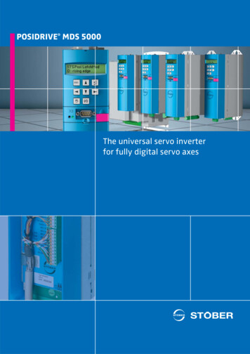
POSIDRIVE MDS 5000The universal servo inverterfor fully digital servo axes
THE FULLY DIGITALPOSITIONING AXISTHE FIRST COMPLETE SYSTEMFOR EFFICIENT AUTOMATIONWith the development of thePOSIDRIVE MDS 5000 servoinverter, STÖBER ANTRIEBSTECHNIK is launching a totalrevision of the hardware andsoftware for the servo system.STOBER EK synchronous servo motorwith digital absolute valuator(standard version)2The data communicationbetween the POSIDRIVE MDS5000 and the STOBER EDEK and EZ synchronous servomotors is now entirely digital.The main factor allowing rationalrealization of this fully digital servo axis lies in the developmentof fully digital absolute encodersat industrial-scale prices. TheSTOBER synchronous servo motors in the ED, EK and EZ seriesare equipped with these devices.Innovative softwaregenerationThe commissioning softwarePOSITool is based on a completely new, modular 3-layerarchitecture with ergonomicinterface design.An applications library with parameterization assistant and anadditional flexible graphics programming facility forms a successful bridge between custommade design and universality.This new system technologybrings to an end the era of overloaded and confusing operatingprograms from the pioneeringperiod of inverters.The benefits are obviousThis comprehensive and rationalslimming down of the systemresults in significant cost benefits for hardware, configuration,cabling, installation and commissioning.The close coordination of allthe STOBER servo componentsis clear from the example of theelectronic motor rating plate.Its data is used automaticallyin the parameterization of thePOSIDRIVE MDS 5000 servoinverter.
Multiple use by alternatecontrol of different servodrivesServo drives often go into actionat timed intervals. Typical examples of this are handling operations and format adjustments.Multimotor operation with onlyone POSIDRIVE MDS 5000servo inverter is suitable forthese applications.SoftwareThe POSITool software can manage up to four separate positionor speed regulated axes andcontrol them alternately.A smooth transition from axisto axis is guaranteed by thesoftware.Power and signal flows arecontrolled with correct timing.The axis management does notrequire additional softwarecomplexity in a primary control.Sequential operation without functional limitationIf four drives are used as endless axes with absolute encoders, the exact positioning is stillfree from rounding errors evenif the gear units have differentand non-integer gear ratios.The digital technologymakes it possibleFor the first time the inexpensiveand reliable axis changeoverapplication is available for unrestricted use on servo drives.Axis changeover switchThe POSISwitch AX 5000 external module has been developedfor connection of the digitallycontrolled synchronous servomotors. Actuation is just via theexisting encoder cables, without further operations.POSISwitch AX 5000ALTERNATECONTROL OF SEVERALSERVO DRIVES3
MODULARSOFTWARE ARCHITECTUREThis conflict of objectives hasbeen addressed by STÖBERANTRIEBSTECHNIK and Software Suite V5 developed as asolution. This suite includesthe commissioning softwarePOSITool, a comprehensivelibrary with standard applications, as well as the firmwarefor the inverter generation 5000.Instead of rigidly defined firmware with an endless numberof parameter variations the userhas a modern, ergonomicallydesigned operator irmwareSuiteThe rapid pace of developmentsin electronics is leading to continuous improvements and expanded functions, especially inservo inverters, and yet this isassociated with constant growthin user software complexity. Atrend which is in stark contrastto the demand for simpler andmore accurate usability.Scalable software architectureFor everydayTo configure a drive, the commissioning software POSITooloffers a library with typicalpreproduced basic applications.Here is a selection:쎲 Fast reference value쎲 Comfort reference valueSpeed or torque referencevalue (selectable)3 analog reference values16 fixed reference valuesMotorized potentiometerPID controller reference valueReference values scalable asabsolute or percentage value쎲 Command positioningPowerful single axis positioning control with commandinterface in accordance withPLCopen and the additionalfunction POSILatch. Positionmeasurements can then betaken on external signals(e.g. linear measurements)쎲 Motion block positioning쎲 Electronic cam functionConnection of up to 32 axesThe consistent project orientation of the modules is provingextremely effective.The parameterization work issupported by assistant functions.MODULAR HFor expertsFunctional housing designThe new, user programmablefirmware has been upgraded toinclude a graphics editor layerin conformance with PLCopen .An experienced or trained userwill find a variety of predefinedfunction blocks in various libraries. With these, basic applications can be modified or givenextra functions.As part of the STOBER EMCstrategy, all the housings in thePOSIDRIVE MDS 5000 seriesare made of galvanized sheetsteel. They shield against electromagnetic interference andthus increase the units' RFIimmunity and reduce interference emission.Extra serviceFor a completely new functionality requirement or for comprehensive adaptation of thebasic application, STÖBERANTRIEBSTECHNIK offers thisas "tailor-made applications"service.The front housing is made ofhigh-impact plastic and incorporates the operator keypad,display, LED indicators, Paramodul and RS232 interface,along with the slots for the optional boards and terminals.The same design plastic fronthousing is used for all the sizes.Other highlightsThe software scalability allowsoptimum adaptation of functionality and response time to theapplication. The cycle time forsetpoint processing dependsonly on the calculation of theactivated system modules andthe parameters.Complex applications can alsobe mapped on the same hardware platform without modifying the firmware.The STOBER POSISwitch AX5000 axis changeover switchis prepared for use on the software side. Up to 4 servo axeswith different functionalitiescan be controlled alternately.ParamodulPlug-in memory module fortransfer of all program and settings data.If a POSIDRIVE MDS 5000 hasto be replaced, the existingParamodul is simply plugged inagain to restart operations. Thefunctionality is retained withoutrestriction.This plug-in memory module isalso an ideal, immediately available tool for documentation updating of operating conditions.SYSTEM CONCEPT OF TOTAL MODULARITY4
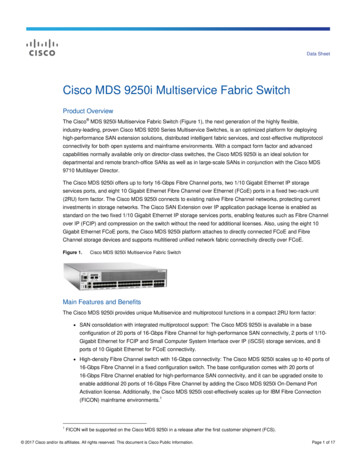
ARDWARE STRUCTURE24 VsupplyECS 5000EtherCAT Supply connection3 x 400 VoltsPROFINETDP 5000PROFIBUS DP-V1CAN 5000CANopen DS 301Optional fieldbus communicationEncoder interfaces for 4 systems:EnDat digital (bidirectional synchronous serial interface)SSI-AbsoluteTTL incremental encoder (RS422, “5 V”)HTL incremental encoder (“24 V”)SEA 5001I/O terminal module– standard –2 analog inputs (12 bit)2 analog outputs5 binary inputs2 binary outputsOptionalI/O interfacesEMC shield, the motor cable shield connected with a clipOn the right: Version with integral brake module for 24 V brakeXEA 5001I/O terminal module– expanded –3 analog inputs(1 x 16 bit, 2 x 12 bit)2 analog outputs13 binary inputs10 binary outputs2 x D-SUB 9 incrementalencoder (TTL) or SSIInput/output interface(X20 – SDS compatible)REA 5001I/O terminal module– Resolver –2 analog inputs, 2 analog outputs5 binary inputs, 2 binary outputsEncoder:ResolverEnDat -Encoder 2.1TTL incremental encoder*SSI encoder*Stepper motor signals*The adapter is included in the scopeof delivery of the REA 5001*(Simulation and evaluation)5
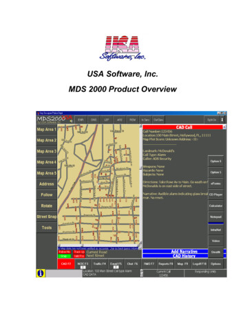
THE COMPLETE RANGEFROM 0.37 TO 45 KWFunctional modular housing designThis increases the units' RFIimmunity and reduces interference emission. The front isthe only part made of plasticwhich is pleasant to the touch.The operator module is thesame for all the sizes.The sheet steel housing designis part of the STOBER EMCstrategy (filter class A). It shieldsagainst electromagnetic interference.70The POSIDRIVE MDS 5000servo inverters can be mountedin compact control cabinets300 mm deep.MDS 5220 A / 5370 A / 5450 ASize 3276105Installation190365383283300MDS 5110 A / 5150 ASize 228330026070MDS5007 A / 5008 A / 5015 AMDS 5040 A / 5075 AMDS 5040 A / 5075 ASize 1MDS 5007 A / 5008 A / 5015 ASize 0175MDS 5110 A / 5150 A283300MDS5220 A / 5370 A / 5450 A6
SYSTEM BASISPowerful processor coreBrake chopper integralEase of installationPOSITool Windows Software32-bit RISC processorCurrent controller 125 µsThermal model monitoring ofexternal resistor for short circuitand overloadAll terminals plug-in type(spring-loaded terminals)Supply and motor connectionsin separate placesDC link terminals, two of each,facilitate parallel connectionEMC plate for shield connectionApplication selection(with assistant)Parameterization(with assistant)Control modesDC link connectionSynchronous servo motorsAsynchronous motors(V/f, sensorless VC, VC)For energy exchange betweenseveral invertersEncoder interfaceOperator unitAbsolute encoder, digital(EnDat , SSI)Incremental encoder (TTL, HTL)Optional: Resolver8 keys, changing of parameters,manual operation (clear textdisplay and LED indicators)Serial interfacePlug-in module for power failure safe storage of all applicationspecific data.Data transfer without any further aidsRS232 with USS protocolOption board slotsCommunicationI/OTerminalsOperational reliabilityGenerously sized power stagefor 250 % accelerating currentThermistor motor protectionPTC thermistor monitoringIDRecommended motor powerSupply voltageLine fusesOption for the implementationof safety functions:쎲 STO and SS1 as perEN 61800-5-2쎲 Stop category 0 and stopcategory 1 as perEN 60204ParamodulIntegration is possible forapplications up to (max.):쎲 PL e in category 3 as perEN ISO 13948-1:2008-12 and쎲 SIL 3 as perEN 61800-5-2:2008-04Control electronics supplyPower supply unit with connection facility for external 24 V orDC link power supply(the control section remainsfully functional even if the supply voltage is switched off)The POSILatch function uses externalsignals and evaluates them as measurement function.POSILatch can replace a separate PLCmeasuring systemSize 0SizeTypeASP 5001Manages several servo invertersin one installationDrive optimization with POSIScope, oscilloscope function forinternal signals (movementvisualization), operational datamonitoring and diagnosisMDS 5007 ASize 1MDS 5008 AMDS 5015 AMDS 5040 AMDS 5075 A55401554025540355404554050.75 kW0.75 kW1.5 kW4.0 kW7.5 kW(L1-L3) 3 x 400 V 32 %/-50 % 50 Hz(L1-L3) 3 x 480 V 10 %/-58 % 60 Hz(L1-N) 1 x 230 V 20%/-40%50/60 Hz1 x 10 AT(L1-L3) 3 x 400 V 32 %/-50 % 50 Hz(L1-L3) 3 x 480 V 10 %/-58 % 60 Hz3 x 6 AT3 x 10 AT3 x 16 AT3 x 20 AT3 x 1.7 A3 x 3.4 A3 x 6.0 A3 x 10 AOperation with synchronous servo motor (servo control mode)Rated current IR3x3AImaxSwitching frequency250 % / 2 sec., 200 % / 5 sec.250 % / 2 sec., 200 % / 5 sec.8 kHz (adjustable to 16 kHz with derating)8 kHz (adjustable to 16 kHz with derating)Operation with three-phase asynchronous motor (V/f, SLVC, VC control modes)Rated current IR3x4AImaxSwitching frequencyBraking resistor internalBraking resistor externalPermissible motor cable length, shieldedConductor cross-sectionEnclosureWeight kg (without packing)Output frequency3 x 2.3 A3 x 4.5 A3 x 10 A3 x 16 A180 % / 5 sec., 150 % / 30 sec.180 % / 5 sec., 150 % / 30 sec.4 kHz (adjustable to 16 kHz with derating)4 kHz (adjustable to 16 kHz with derating)––100 Ω: max. 3.2 kW100 Ω: max. 1.6 kW100 m, from 50 m with output chokemax. 2.5 mmIP 20247 Ω: max. 6.4 kW47 Ω: max. 13.100 m, from 50 m with output chokemax. 4 mm2IP 202.23.80 – 700 Hz0 – 700 Hz7
.6 kWSYSTEM OPTIONSCE complianceFieldbus communicationAll POSIDRIVE MDS 5000 inverters conform to the applicableEMC Directives and meet thecriteria of Low Voltage DirectiveEN 50178. Standard featurescomprise an effective range ofmeasures, among them an integral EMC filter and the highquality galvanized sheet steelinverter housing.Levels and terms apply as defined by IEC 1131.All POSIDRIVE servo invertersare CE-markedPROFIBUSPROFINETEtherCAT CANopen UL compliantThe inverters are UL and cUL("Canadian UL") listed and meetthe requirements of UL 508Cand UL 840 standardsAbsolute Encoder Support AESFor buffering supply voltagewhen using the inductive Multiturn EnDat 2.2 absolute encoderEBI1135 (when the 24 V powersupply to the inverter has beenswitched off)ASP 5001Starting lockoutI/O terminal moduleSEA 5001XEA 5001 (incremental encoderand SSI interfaces)REA 5001Resolver andEnDat Encoder 2.1 interfaceVHPRBraking resistorPOSISwitch AX 5000For sequential control of STOBERED, EK and EZ synchronous servo motors with digital absoluteencoders.Submountedbraking resistorsBraking resistors for installationat the rear of the unitBraking resistorVHPR seriesIP 54 enclosure, ULup to 400 WSize 2Size 3MDS 5110 AMDS 5150 AMDS 5220 AMDS 5370 AMDS 5450 A554065540755408554095541011 kW15 kW22 kW37 kW45 kW(L1-L3) 3 x 400 V 32 %/-50 % 50 Hz(L1-L3) 3 x 480 V 10 %/-58 % 60 Hz(L1-L3) 3 x 400 V 32 %/-50 % 50 Hz(L1-L3) 3 x 480 V 10 %/-58 % 60 Hz3 x 35 AT3 x 50 AT3 x 50 A gG3 x 80 A gG3 x 85 A gG3 x 14 A3 x 20 A3 x 30 A3 x 50 A3 x 60 A250 % / 2 sec., 200 % / 5 sec.250 % / 2 sec., 200 % / 5 sec.8 kHz (adjustable to 16 kHz with derating)8 kHz (adjustable to 16 kHz with derating)3 x 22 A3 x 32 A3 x 70 A3 x 44 A3 x 85 A180 % / 5 sec., 150 % / 30 sec.180 % / 5 sec., 150 % / 30 sec.4 kHz (adjustable to 16 kHz with derating)4 kHz (adjustable to 16 kHz with derating)–30 Ω: 100 W / max. 21 kW22 Ω: max. 29.1 kW15 Ω: max. 42 kW100 m, from 50 m with output chokemax. 6 mm100 m22max. 35 mm without connector sleeveIP 205.00 – 700 HzIP 2013.211.80 – 700 Hz
ACCURATE COMMISSIONINGDigital drive tuningThe Windows commissioningsoftware POSITool contains thefollowing functions:쎲 Application configuration쎲 Drive parameterization쎲 Drive programming쎲 Drive commissioning쎲 Application commissioning쎲 Function optimizationThe prepared functions and parameters are transferred via theRS232 interface on the devicefront.Commissioningthe complete applicationSTOBER EKsynchronousservo motorwith digitalabsolute encoderon the motorshaft (B side)Commissioning the STOBERED, EK and EZ synchronousservo motorsNo software knowledge is necessary for this preparation work.All the adjustments are done bydialog via the operator panel withtext display. The POSIDRIVE MDS 5000 servo inverter comessupplied with the “rapid set point”application.The POSIScope software toolreduces trial runs for individualdrive optimization to a minimum.Trial and error is replaced by afull diagnosis. In real time theprocedure is observed, recorded,analyzed and immediately displayed by oscillograph on thePC monitor. The fine tuningthus obtained results in perfectlyadjusted drives.On applications with high specifications, POSIScope can beused for system maintenance.This can be done either via theconnected PC or after data transfer via the device operator panel.The Paramodul is also suitablefor data transfer. Further parameterization corrections andadditions can be made directly.Some knowledge (basic training)is necessary for this task.Advanced seminars forgeneral users and expertsThe POSITool software assistantsupports configuration and parameterisation of the STOBERstandard applications. Basic andadvanced information on the safehandling of POSITool necessaryon the job can be acquired at anapplication seminar.In practical, individually designedseminars, general users learnthe ways in which they can utilise the potential of the POSIToolstandard applications fully andeffectively.After attending the ‘Free GraphicProgramming’ seminar, expertscan expand the POSITool standard applications themselvesto adapt them to specific needs.Further information and datescan be found on our websitewww.stoeber.de (Services).
QUICK TO ASSEMBLEPerfect, practical connectionlayoutServiceThis full service concept guaranteeslocal expertise and availability whenneeded.The mains or 24 V supply connection is made ‘from above’through a plug-in terminal strip.The separate connections formotor, DC link and braking resistor are located on the bottomof the housing. The PTC thermistor and braking relay are alsoattached here by simple plug-inmounting.In general, the service specialists can bereached at any time via a 24/7 servicehotline.When necessary, a problem can beaddressed immediately.24/7 service hotline 49 180 5 786323Quick DC link connection.Double DC link permit enablesimplified parallel connection.VERY EASY TO USEEasy data transfer and acceptance by Paramodul.STOBER JAPANwww.stober.co.jp 81 3 5395 6788sales@stober.co.jpSTOBER CHINASTOBER SOUTH EAST ASIAwww.stoeber.cn 86 10 6590 7391sales@stoeber.cnwww.stober.sg 65 65112912sales@stober.sgSTOBER FRANCESTOBER SWITZERLANDwww.stober.fr 33 4 78.98.91.80sales@stober.frwww.stoeber.ch 41 56 496 96 50sales@stoeber.chSTOBER GERMANYSTOBER USAwww.stoeber.de 49 7231 582-0sales@stoeber.dewww.stober.com 1 606 759 5090sales@stober.comSTOBER ITALYDisplay and keypad are integrated. Rapid diagnosis, statusmonitoring, direct parameteraccess and manual operatingfunctions are possible.www.stober.comSTOBER AUSTRIAwww.stoeber.at 43 7613 7600-0sales@stoeber.atwww.stober.it 39 02 93909570sales@stober.itSubject to technical changes 441812.07 www.wast.deThe STOBER service system comprises38 expert partners in Germany andmore than 80 companies in the STOBERSERVICE NETWORK worldwide.
As part of the STOBER EMC strategy, all the housings in the POSIDRIVE MDS 5000 series are made of galvanized sheet steel. They shield against elec-tromagnetic interference and thus increase the units' RFI immunity and reduce interfe-rence emission. The front housing is made of high-impact plastic and incor - porates the operator keypad,