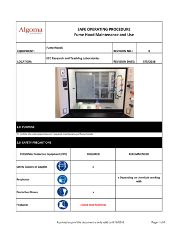
Transcription
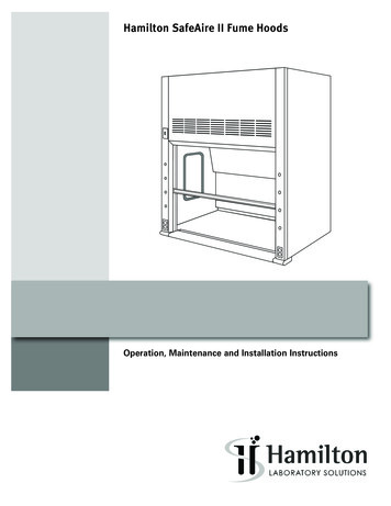
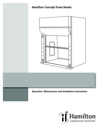
Hamilton Concept Fume HoodsOperation, Maintenance and Installation Instructions
Hamilton Concept Fume HoodTable of ContentsIntroduction . . . . . . . . . . . . . . . . . . . . . . . . . . . . . . . . . . . . . . . . . . . . . . . . . . . . . . . . . . . . 4Fume Hood Identification . . . . . . . . . . . . . . . . . . . . . . . . . . . . . . . . . . . . . . . . . . . . . . . . . . 4Perchloric Acid Fume Hoods . . . . . . . . . . . . . . . . . . . . . . . . . . . . . . . . . . . . . . . . . . . . . . . 4Warning and Operating Instructions. . . . . . . . . . . . . . . . . . . . . . . . . . . . . . . . . . . . . . . . . 5Installation – Bench Top Fume Hood . . . . . . . . . . . . . . . . . . . . . . . . . . . . . . . . . . . . . . 6-9Fume Hood Superstructure Installation . . . . . . . . . . . . . . . . . . . . . . . . . . . . . . . . . 6-7Two-piece Fixed Baffle Installation . . . . . . . . . . . . . . . . . . . . . . . . . . . . . . . . . . . . . . . 8Side Enclosure Panel Installation . . . . . . . . . . . . . . . . . . . . . . . . . . . . . . . . . . . . . . . . 8Sash Cover and Ceiling Front Enclosure . . . . . . . . . . . . . . . . . . . . . . . . . . . . . . . . . . 9Ceiling Side and Rear Enclosure Installation . . . . . . . . . . . . . . . . . . . . . . . . . . . . . . 9Installation – Floor-mounted Fume Hood . . . . . . . . . . . . . . . . . . . . . . . . . . . . . . . . 10-22Exhaust Filter Installation . . . . . . . . . . . . . . . . . . . . . . . . . . . . . . . . . . . . . . . . . . . . . . 22Minihelic Gauge Installation . . . . . . . . . . . . . . . . . . . . . . . . . . . . . . . . . . . . . . . . . . . . 22Fume Hood Monitor . . . . . . . . . . . . . . . . . . . . . . . . . . . . . . . . . . . . . . . . . . . . . . . . . . . 22Maintenance and Adjustments . . . . . . . . . . . . . . . . . . . . . . . . . . . . . . . . . . . . . . . . . 23-30General Maintenance of Fume Hoods . . . . . . . . . . . . . . . . . . . . . . . . . . . . . . . . . . . 23Fume Hood Inspection Procedures . . . . . . . . . . . . . . . . . . . . . . . . . . . . . . . . . . . . . . 23Cleaning Fume Hood Interiors . . . . . . . . . . . . . . . . . . . . . . . . . . . . . . . . . . . . . . . . . . 23Fluorescent Light Tube Replacement . . . . . . . . . . . . . . . . . . . . . . . . . . . . . . . . . . . . 24Access Panel Gasket Removal . . . . . . . . . . . . . . . . . . . . . . . . . . . . . . . . . . . . . . . . . 24Access Panel Gasket Installation. . . . . . . . . . . . . . . . . . . . . . . . . . . . . . . . . . . . . . . . 24Access Through Front Posts . . . . . . . . . . . . . . . . . . . . . . . . . . . . . . . . . . . . . . . . . . . . 25Roller Chain Replacement . . . . . . . . . . . . . . . . . . . . . . . . . . . . . . . . . . . . . . . . . . . . . . 26Top-hung Combination Sash Glass Replacement . . . . . . . . . . . . . . . . . . . . . . . . . . 26Top-hung Combination Sash Roller Replacement. . . . . . . . . . . . . . . . . . . . . . . . . . 27Fixed Glass Panel Replacement . . . . . . . . . . . . . . . . . . . . . . . . . . . . . . . . . . . . . . . . . 27Unframed Sash Glass Replacement. . . . . . . . . . . . . . . . . . . . . . . . . . . . . . . . . . . . . . 28AutoSash Adjustment and Replacement . . . . . . . . . . . . . . . . . . . . . . . . . . . . . . . . . 29Blower RPM Adjustments . . . . . . . . . . . . . . . . . . . . . . . . . . . . . . . . . . . . . . . . . . . . . . 30Monitoring Exhaust Filters Using a Manometer Assembly . . . . . . . . . . . . . . . . . . 30Fume Hood Testing . . . . . . . . . . . . . . . . . . . . . . . . . . . . . . . . . . . . . . . . . . . . . . . . . . . 31-33Troubleshooting . . . . . . . . . . . . . . . . . . . . . . . . . . . . . . . . . . . . . . . . . . . . . . . . . . . . . . . . . 34Dimensions are nominal, and illustrations and specifications are based on the latest product informationavailable at the time of publication. The right is reserved to make changes at any time without notice.1
IntroductionFume hoods are exposed to temperature extremes, reagentfumes and work surface abuse. Regular care will prolongservice life and ensure safe working conditions.The exhaust system and fume hood blower must functionproperly for safety.Air velocity checks can be made with a thermalanemometer. See Fume Hood Inspection Procedures,page 31 and Field Evaluation, page 32.Always place equipment and apparatus as far back intothe fume hood as possible to provide greater assurance ofproper fume collection and removal.Large, bulky apparatus or equipment should be positioned inthe fume hood to permit air flow around it. Raise large itemsan inch or two above work surface. Spilled liquids, acids orcorrosive materials should be cleaned immediately and thesurface neutralized with water or a proper neutralizing agentto prevent damage to the fume hood interior, work surfaceand apparatus or equipment installed in the fume hood.Special fume hoods are required for the handling ofPerchloric Acid.This product was not evaluated for use withPerchloric Acid or Radioisotopes by UL.Hamilton Concept Fume HoodPerchloric Acid Fume HoodsThe properties of perchloric acid require that a speciallydesigned fume hood be set aside for exclusive use with thismaterial. The fume hood is equipped with a cold water spraydevice for washdown of the interior surfaces. A trough isplaced across the back of the fume hood for collection anddisposal of washdown waters. Operating personnel shouldbe well trained in the proper handling techniques and befamiliar with the characteristics of this material.Frequency of washdown, both fume hood interiorand exterior system, is determined by the usage andconcentration of reagents. This can range from a weeklyprocedure to one that occurs after every use. Washdownshould always be followed by an inspection to verify thatall areas are clean and that the wash system is functioningproperly.Some of the hazards of perchloric acid which justify the useof a special fume hood are:1. Perchloric acid is a very strong acid, capable ofproducing severe burns when in contact with skin, eyes orrespiratory tract.2. As an aqueous solution, it can cause violent explosions ifimproperly handled.3. It reacts with other substances to form unstable materialswhich are susceptible to exploding either by impact,friction, or spontaneous combustion.Persons using perchloric acid should be thoroughly familiarwith its hazards. Many reported laboratory accidents haveinvolved less than one gram of reactant. Listed below aresome common safety practices that should be followed:2!Spilled perchloric acid should be thoroughly washed awaywith large amounts of water.!The use of organic chemicals or materials in the fume hoodshould be avoided.!Effective eye protection should always be used, as well asutilization of the fume hood sash for additional safety.!Gas flames or oil baths should not be used within the fumehood.!Organic chemicals should not be kept in storage areas setaside for perchloric acid storage.!A schedule should be made for regular washdown andinspection of fume hood interior, ductwork and blower toguard against a build-up of dangerous perchloric materials.!Only fluorocarbon grease should be used as a blowerlubricant as any other type is considered potentiallyhazardous.!Washdown procedure should be performed aftercompletion of usage with all apparatus removed from fumehood.hamiltonlab.com
Hamilton Concept Fume HoodFume Hood rBaffles3
Warning and Operating InstructionsWarningThis product is intended for use with certain chemicals thatcan cause serious injury or illness through inhalation orphysical contact. While this product is intended to minimizeexposure to certain hazardous chemicals when selected,installed and operated properly, its performance and thesafety of the user is affected by a number of factors. Theseinclude the HVAC system, the specific chemicals andprocesses being used, proper operation and the condition ofthe room.Before using this fume hood, consult the owner’s industrialhygienist or safety representative to ensure:1) The specific fume hood alarms, controls and the HVACsystem have been properly selected and are operatingcorrectly;2) The fume hood has been tested after installationand routinely thereafter to ensure the fume hood isproviding the proper containment for the specificchemicals and processes being used;3) There has been appropriate training on the correct useof the fume hood and handling of the specific chemicalsand the fume hood operating instructions have beenreviewed;4) Any personal protective devices that are required areproperly selected and provided;5) The fume hood is being operated at the appropriateface velocity. The fume hood should never be operatedwith the sash in the full open position.Hamilton Concept Fume HoodOperating InstructionsFailure to follow these instructions could result in physicalinjury or illness.Caution: Do not use fume hood for perchloric acidprocedures.1. Do not use this fume hood unless you have receivedproper training from the owner’s industrial hygienist orsafety representative.2. This fume hood is not intended to be used with allchemicals or all chemical processes. Consult the owner’sindustrial hygienist or safety representative to determinewhether the fume hood is appropriate for the chemicalsand processes to be used.3. Verify that the fume hood exhaust system and controlsare operating properly and providing the necessary airflow. If in doubt, the owner’s industrial hygienist or safetyrepresentative should be consulted. It is recommendedthat the fume hood be equipped with an air flowmonitoring device. Before using the fume hood, verify thatthe monitor is operating properly by testing the monitor.4. The fume hood should not be operated with the sash inthe full open (setup) position. When the fume hood is inuse, the opening of the sash glass should be kept at aminimum. On a vertical rising sash, the sash glass shouldbe no higher than 18”. The sash should remain closedwhen the fume hood is not in use.5. Place chemicals and other work materials at least six (6)inches inside the sash.6. Do not restrict air flow inside the fume hood. Do not putlarge items in front of the baffles. Large apparatus shouldbe elevated on blocks. Remove all materials not neededfor the immediate work. The fume hood must not be usedfor storage purposes.7. Never place your head inside the fume hood.Refer to operationinstructions label onleft side of sash glass.8. External air movement can affect the performance ofthe fume hood. Do not operate near open doors, openwindows or fans. Avoid rapid body movements. Do notopen the fume hood if there are cross drafts or turbulencein front of the hood. Do not open the sash rapidly.9. Wear gloves and other protective clothing if contact withcontaminants is a hazard.10. Clean spills immediately.11. If fumes or odors are present, stop operating the fumehood, close the sash and contact the owner’s industrialhygienist or safety representative immediately.12. It is recommended that this fume hood be tested andcertified annually by the owner according to applicableindustry and government standards.4hamiltonlab.com
Hamilton Concept Fume HoodInstallation – Bench Top Fume Hood1. Remove screws from sash hold-down clips. Open the sashand remove blocking, using care not to damage sill orbaffles.5. Remove shipping screws holding the fume hood frameto the skid. Save four of these screws, No. 10 x 5/8”, tosecure hood to the work surface.6. Place the fume hood on the work surface using care toprotect the work surface.CounterweightFour BoltsRear SupportChannelsScrewsFigure 1Figure 3Work Surface2. Release counterweight by removing four bolts that securethe counterweight to the rear support channels.3. Remove tape securing fixed glass panel on combinationsash hoods.7. Drill two each 1/8” diameter pilot holes at each side ofstructural frame and into the work surface. Secure withfour No. 10 x 5/8” screws saved from the shipping skid.8. Caulk hood to work surface with silicone sealant.9. Check the following items:Upper FrontEnclosurePanelScrews andKeyhole Slots!The counterweight operates free of obstructions.!There is proper horizontal sash alignment andcounterweight balance.!The sash does not bind in the sash guides.10. Baffles can be installed at this time. See page 11.Figure 24. Loosen, but do not remove, screws securing upper frontenclosure panel to superstructure.5
Hamilton Concept Fume HoodInstallation – Bench Top Fume HoodRoller ChainAutoSashCableCounterweightSprocketsAutoSash BeltFigure 410. Check alignment of roller chain with sprockets.11. Check counterweight balance and unrestrictedmovement.Rear of Hood SuperstructureFigure 613. Check AutoSash belt and cable have unrestrictedmovement.Sash14. Check sash travel for unrestricted movement.Adjusting NutAccess through sloton underside of sill1/4”SillFigure 512. Level sash by adjusting the two nuts (one at each cornerpost) securing the roller chains to the sash. Nuts areaccessible from beneath the hood, reaching through thelarge slot on the underside of the sill. Threaded shankshould protrude past leveling nut a minimum of 1/4” afteradjustment.6hamiltonlab.com
Installation – Bench Top Fume HoodHamilton Concept Fume HoodTwo-piece Fixed Baffle InstallationSide Enclosure Panels Installation1. Place paper screen on top of upper support brackets.1. Lower the side panel into the side frame of the fume hood,engaging the frame’s lower lip.2. Place top baffle into position by engaging top edge intolip of the three ceiling blocks. Lift and lock baffle into topside of upper support brackets.3. Place bottom baffle into position. Place top edge of baffleinto the forward slot of the upper support bracket. Lift andlock baffle into lower support brackets.2. While pressing down on the two black catches, rotate theside panel and engage the frame’s upper lip. Gently applyadditional pressure to the panel and release the catchesto secure the panel to the hood.CatchesPaper ScreenInstalled HereSide PanelTop BaffleTop BaffleLower LipFigure 8Upper Support BracketBottom BaffleBottom BaffleLower BracketFigure 77
Hamilton Concept Fume HoodInstallation – Bench Top Fume HoodSash Cover and Ceiling Front Enclosure InstallationCeiling Side and Rear Enclosure Panel InstallationSupport postSash Enclosure4-ScrewsRear EnclosurePanelSide EnclosurePanelFrontEnclosurePanelCatchesFront EnclosurePanelFigure 91. Place sash enclosure on top of hood. Route the rollerchains and lamp wiring through the appropriate openingsin the enclosure.SideEnclosurePanel2. Fasten sash enclosure to top of hood with four screws.3. Raise front enclosure panel to top of hood and engage thebottom lip of front enclosure panel into the top edge of thehood’s corner posts.4. While pressing down on the two black catches, rotate thefront panel to engage the sash cover’s upper lip. Gentlyapply additional pressure to the front panel and releasethe catches to secure the front panel to the sash cover.Figure 101. Fasten the support posts to the upper rear corners of thetop of the hood.2. Hang ceiling side enclosure panel onto sash cover/frontenclosure panel assembly and support post.3. Hang ceiling rear enclosure panel onto support posts.8hamiltonlab.com
Hamilton Concept Fume HoodInstallation – Floor-mounted Fume Hood(A) Floor Mounted Fume Hood InstallationSee Section AA, page 18, for horizontal sliding sash doorassembly.1. Floor-mounted fume hoods are only shipped unassembled.Onsite assembly, with assistance, is required.(B) Fume Hood Assembly1. All necessary services such as gas, water and electricalshould be roughed in to the proper area where units willbe located.Refer to Figure 112. Locate the left hand side assembly panel (2) and the backassembly (1).3. Stand the back panel (1) in a vertical position. Slide theside panel (2) into the end of the back panel assembly.Make sure the angled flange on the side panel (2) fitsbetween back panel and horizontal members of backpanel assembly (1).4. Align the two holes at the top and bottom of the panelsand secure with No. 8 x 3/4” phillips pan head screws (3).5. Locate the right hand panel and attach it in the samefashion.Figure 119
Installation – Floor-mounted Fume HoodHamilton Concept Fume Hood(B) Fume Hood Assembly – continued6. If the baffle support brackets (4) have not been factoryinstalled, attach all of the baffle support brackets tothe back panel. Insert two No. 8 x 3/4” pan head threadcutting screws from the rear of the back panel (1) intoeach support bracket.10. Locate the right rear sprocket assembly (8). Attach itat the rear of the top panel assembly using three 1/4 x1” hex head machine screws (9) lock washers (9A) andnuts (9B).Refer to Figure 12Figure 127. Locate the top assembly (6) and place it on top of thepreviously assembled back and side panel assembly (1).8. Align all top assembly holes to the rear and side panelassembly holes (1).9. Secure the top assembly (6) to the rear and side panelassembly (1) with No. 8 x 3/4” pan head sheet metalscrews (7). Secure the exhaust collar to the rear upperassembly rail.Figure 1311. Locate the left rear sprocket assembly (8A) and attach itat the rear of the top panel assembly. Secure with three1/4 x 1” hex head machine screws (9) lock washers (9A)and nuts (9B).The left and right sprocket assemblies (8 and 8A) are NOTinterchangeable.Refer to Figure 1310hamiltonlab.com
Hamilton Concept Fume HoodInstallation – Floor-mounted Fume Hood(B) Fume Hood Assembly – continuedFigure 14Figure 1512. Locate the header panel (10). Place it against the frontprotruding flange of the top assembly (6).13. Secure the top of the header panel to the flange with fiveNo. 8 x 5/8” pan head sheet metal screws (11).(C) Baffle InstallationRefer to Figure 151. Locate the four baffles (12-15) for installation. Begin withinserting the lower baffle (12) into the baffle supportbrackets (4).2. Install the rest of the baffles (13-14) in a similar manner.Refer to Figure 163. Insert the upper baffle (15) by sliding it behind the upperbaffle extrusion (16). Allow the lower end of the baffle toseat into the upper slot of the baffle support bracket (4).Figure 1611
Installation – Floor-mounted Fume Hood(D) Combination Hood Sash Glass InstallationHamilton Concept Fume Hood(E) Sash InstallationFigure 171. Locate the upper sash glass (18) and carefully slide itdown into the factory installed fixed glass supports (17).Refer to Figures 17, 18Figure 19For horizontal sliding sashes, see Section AA, page 17.The sashes must be attached to the unit before front chainsprocket assembly is mounted.The front (lower) sash must be assembled first. Assistance isrequired.1. Carefully install the front sash (20) by raising it up andguiding it down into the front left and right sash tracks.Allow sash to rest at the bottom.2. In a similar manner, install the rear (upper) sash (19) byraising it up and guiding it down into the rear left and rightsash tracks. Allow sash to rest on stops.Figure 1812hamiltonlab.com
Hamilton Concept Fume HoodInstallation – Floor-mounted Fume Hood(E) Sash Installation – continuedFrontFigure 21Figure 203. Locate the front sprocket support assembly (21). Orientthe sprocket assembly with the small idler sprockets tothe front of the unit.6. The rear/upper sash door chain must be installed first.Locate one of the short chains (25) and check for properorientation. Make sure the master link for the sash doorsis to the inside. (See Figure 22)4. Attach each end of the sprocket assembly to the topof the unit with two 1/4” x 1” hex head bolts (22), lockwashers (23) and nuts (24).7. Thread the chain over the rear lower sprocket (27).Continue threading the chain over the large sprocket (28)at the front of the unit.Refer to Figure 208. Repeat Steps 6 and 7 for chain on the opposite side.5. Note that sash chains (25, 26) are provided in two lengths.A longer chain for the front/lower sash and a shorterchain for the rear/upper sash.Refer to Figure 21Master LinkTo InsideFigure 2213
Installation – Floor-mounted Fume HoodHamilton Concept Fume Hood(E) Sash Installation – continued9. Attach the front lower chain assembly (25) to the sash byinserting the threaded end of the chain assembly (32) intothe lower sash mount (33). Secure using a 1/4” Ny-Locknut (34).Rear View of Unit10. Repeat Step 9 for attaching chain on the opposite side.Refer to Figure 2211. Locate the remaining longer chain (26). Make sure it isproperly oriented. Ensure the master link for the sashdoors is positioned to the inside.12. Thread the chain over the rear upper sprocket (29).Continue threading the chain over the upper front idlersprocket (30) and down behind the lower sprocket (31).Repeat for opposite side.Refer to Figure 2113. In a similar manner, repeat Steps 9 and 10 to attach thechain (26) to the front lower sash mounts. (See Figure 22)(F) Attaching Sash Door Chains to Weight PansFigure 23Assistance is required.1. Note that there are front and rear weight pan assemblieswhich are located at the rear of the unit. These weightpans should not be interchanged.2. Weight pans can be identified by the number of pocketsand pocket locations. The front weight pan has onecenter pocket. The rear weight pan has two outsidepockets.Refer to Figure 233. Locate the front weight pan and remove two pan guidemounting screws from one end and remove the guide.4. Position the opposite end of the pan and guide into thefront guide channel.5. Swing the other end of the weight pan and position it intothe remaining front guide channel on the opposite side.Reinsert the original pan guide from the bottom and slideit up into position. Attach the guide to the weight pan withthe two screws removed previously in Step 3.6. Locate the rear weight pan with the two outside pocketsand attach it to the rear guide channels in a similarmanner following Steps 3, 4, and 5.Figure 24Refer to Figure 2414hamiltonlab.com
Hamilton Concept Fume HoodInstallation – Floor-mounted Fume Hood(F) Attaching Sash Doors Chains to Weight Pans – continued7. Raise the upper/rear sash and block it up to allow slack inthe chain at the rear.8. Open the threaded chain link (35) and insert it through thehole in the end of the weight pan. Close the chain link,securing the weight pan. Repeat this step for the oppositeside.9. Repeat Steps 7 and 8 and attach the lower/front sashchain to the rear weight pan in similar manner.Refer to Figure 2510. Locate the autosash assembly (36) and attach it to the topof the unit using two No. 8 x 3/4” pan head sheet metalscrews (37).Refer to Figure 26Figure 25Figure 2711. The autosash strap (38) must be attached to the frontweight pan.12. Pull the strap down and align the hole with the squarehole in the weight pan.13. Attach the strap to the weight pan using a 1/4 x 3/4”carriage bolt (39). Insert bolt from the front of the weightpan through the square hole and into the hole in the sashstrap.14. Secure the strap to the weight pan using a 1/4” Ny-Locknut (40).Refer to Figure 27Figure 2615
Installation – Floor-mounted Fume HoodHamilton Concept Fume Hood(G) Final Sash Door Operation and Adjustments4. Locate the upper front enclosure (43). This enclosure alsohas two keyhole slots which fit onto the two upper set ofscrews located on the front of the fume hood.5. Set the upper front enclosure (43) in place above thepreviously installed lower enclosure.Refer to Figure 30Figure 281. Test each sash operation by raising and lowering. Thedoors should move easily with no binding in the tracks.2. The sashes should remain stationary when moved tovarious positions.3. If sashes do not remain in stationary positions, more orless weight may have to be added or removed from theweight pans.Figure 294. Check to make sure the sashes are level. There should beno gaps at the top or bottom of the sashes when they areclosed.5. Make any necessary adjustments.(H) Attaching Upper and Lower Front Enclosures1. Locate the lower front enclosure (41). The enclosure hastwo keyhole slots which fit onto the two lower screwslocated on the front of the fume hood.2. Attach the lower enclosure and secure with two No. 8 x1/2” pan head screw (42).3. Ensure proper position of the mounting screw (42) andlower enclosure (41).Refer to Figure 28,29Figure 3016hamiltonlab.com
Hamilton Concept Fume HoodInstallation – Floor-mounted Fume Hood(J) Service Connections and Final Hood Assembly(AA) Sash Floor Guide Attachment1. Place the hood in its permanent location in the lab if thishas not already been done.The basic fume hood units for both vertical and horizontalsashes are identical. The only difference is sash doorassembly.2. All service connections can now made. Qualifiedtradesman are recommended for all plumbing, electricaland gas installations.3. This completes assembly of the Concept Floor-mountedFume Hood.Refer to Figure 311. Locate the sash floor guide (2) and align it with thefront of the fume hood unit. Temporarily secure it to thefloor. Hardware is installer supplied. It is the installers’discretion for type of anchoring used depending onconstruction and floor type.2. Permanent anchoring can be done after sashes are fullyassembled, plumbed and slide freely.Figure 3117
Installation – Floor-mounted Fume HoodHamilton Concept Fume Hood(BB) Attaching the Upper Sash Hanger and TracksThe front sash track is factory assembled to the hangerassembly.Refer to Figure 33Refer to Figure 321. Slide the sash hanger and track assembly (3) to the upperinside of the fume hood unit. The sash door track must bepositioned to the front of the unit. (See Figure 4)2. Locate four 3/8 x 3/4” hex head bolts, lock washers andnuts.Figure 333. Attach each end of the sash hanger and track assembly(3) to the inside of the fume hood unit using two 3/8 x 3/4”hex head bolts (4), lock washers (5), and nuts (6).Figure 32Four sashes are required; two in front and two behind.Front and Rear Sashes are interchangeable.18hamiltonlab.com
Hamilton Concept Fume HoodInstallation – Floor-mounted Fume Hood(CC) Sash Track OrientationFrontEnd ViewHorizontal SlidingSash DoorAssemblyEnd ViewFigure 341. Figure 34 Illustrates proper orientation of the sash trackhanger (3) and upper outside sash track.Figure 352. Locate one of the horizontal sashes and place the rollersinto the front sash track. Make sure track is clean.3. Make sure the sash fits properly into the lower outsidefloor guide (2). Readjust floor guide if necessary forsmooth operation.4. Repeat for the remaining front sash.5. Attach the sash retainer bracket (7) to the sash trackusing four No. 8 x 3/8” pan head sheet metal screws (8).19
Installation – Floor-mounted Fume HoodHamilton Concept Fume Hood(CC) Sash Track Orientation – continuedHorizontalSash DoorAssembliesHorizontalSash DoorAssemblyEnd ViewFigure 36End ViewFigure 376. Locate the remaining sash track (9) and attach it to theinside of the sash hanger (3). Make sure it is properlyoriented.8. Locate horizontal sash. Set the sash rollers into the rearsash track (9) installed previously. Make sure the track isclean.7. Secure the sash track (9) using six No. 8 x 3/8” pan headsheet metal screws (10).9. Check to make sure the sash fits properly into the lowerinside floor guide (2).10. Repeat Steps 8 and 9 for the remaining sash.11. Locate the remaining sash retainer bracket (11) andattach it to the sash track using four No. 8 x 3/8” panhead sheet metal screws (12).12. Check to make sure that both sashes fit properly into thelower floor guide (2). Make sure the sashes move freely.13. Permanently attach the lower floor guide to the floor tocomplete assembly.20hamiltonlab.com
Installation and IdentificationHamilton Concept Fume HoodExhaust Filter InstallationProduct Numbers 54L29600, 54L29700, 54L29800 and 54L29900Pre-filter CoverThe pre-filter cover facesforward on RestrictedBypass and ConstantVolume Bypass hoods.Front ofFume HoodFigure 11Securely attach the filter inlet collar to hood exhausttransition using same method as followed in the duct system.Filter outlet may be attached to duct using flexible connectoror same as inlet connection.Fume Hood MonitorProper fume hood operation is key to laboratory safety,comfort and energy management. OSHA requires thatlaboratories take measures to ensure proper and adequateoperation of fume hoods. Recommendations include the useof a continuous air monitoring device. The ANSI Z9.5 andNFPA 45 standards reinforce these requirements.Fume hood monitors have the ability to monitor true fumehood face velocity using thermal sensors located in theinstrument. The thermal sensors are exposed to cleanlaboratory air only. They can be surface-mounted in minuteseliminating the need for expensive panel cutouts.Each model is equipped with indicator lights that illuminatebased on a predetermined set-point. An audible 85dBpiezoelectric alarm sounds and a red indicator lightilluminates to warn of potentially dangerous low air flowconditions.Fume hood monitors are shipped with operation manuals.Minihelic Gauge InstallationSensor block and sensortube, two required eachConnect to low side ofMinihelic GaugeThick-wall vinyl laboratorytubing, cut to lengthMinihelic Gauge range 0”-3”W.C., reads filter pressuredropFront PostConnect to high side of Minihelic GaugeFigure 12Replacement filter sets consist of one rough and one HEPA filter.Product Number 54L30200 – Filter set for 54L29600 or 54L29800.Product Number 54L30000 – Filter set for 54L29700 or 54L29900.21
Maintenance and AdjustmentsHamilton Concept Fume HoodGeneral Maintenance of Fume HoodsFume Hood Inspection ProceduresFume hood maintenance procedures consist primarily ofcleanup, adjustment, lubrication, and replacement of worn,damaged or non-functioning parts. Lubrication of sashguides, cables, pulley wheels, and other working partsshould be accomplished as required and replacement ofbroken, worn, or non-fu
Perchloric Acid Fume Hoods The properties of perchloric acid require that a specially designed fume hood be set aside for exclusive use with this material. The fume hood is equipped with a cold water spray device for washdown of the interior surfaces. A trough is placed across the back of the fume hood for collection and disposal of washdown .