Transcription
Hamilton SafeAire II Fume HoodsOperation, Maintenance and Installation Instructions
Hamilton SafeAire II Fume Hood2hamiltonlab.com
Hamilton SafeAire II Fume HoodTable of ContentsGeneral Information . . . . . . . . . . . . . . . . . . . . . . . . . . . . . . . . . . . . . . . . . . . . . . . . . . . . 4–5General . . . . . . . . . . . . . . . . . . . . . . . . . . . . . . . . . . . . . . . . . . . . . . . . . . . . . . . . . . . . . . . 4Perchloric Acid Fume Hoods . . . . . . . . . . . . . . . . . . . . . . . . . . . . . . . . . . . . . . . . . . . . 4Fume Hood Identification . . . . . . . . . . . . . . . . . . . . . . . . . . . . . . . . . . . . . . . . . . . . . . . 5Installation . . . . . . . . . . . . . . . . . . . . . . . . . . . . . . . . . . . . . . . . . . . . . . . . . . . . . . . . . . . 6-10Fume Hood Superstructures . . . . . . . . . . . . . . . . . . . . . . . . . . . . . . . . . . . . . . . . . . . . . 6Knock-Down Floor-Mounted Fume Hoods . . . . . . . . . . . . . . . . . . . . . . . . . . . . . . 7–11Baffles . . . . . . . . . . . . . . . . . . . . . . . . . . . . . . . . . . . . . . . . . . . . . . . . . . . . . . . . . . . . 12–13Blower Enclosures . . . . . . . . . . . . . . . . . . . . . . . . . . . . . . . . . . . . . . . . . . . . . . . . . . . . 14Fume Hood Monitor . . . . . . . . . . . . . . . . . . . . . . . . . . . . . . . . . . . . . . . . . . . . . . . . . . . 15Exhaust Filter Assembly . . . . . . . . . . . . . . . . . . . . . . . . . . . . . . . . . . . . . . . . . . . . . . . 15Minihelic Gauge . . . . . . . . . . . . . . . . . . . . . . . . . . . . . . . . . . . . . . . . . . . . . . . . . . . . . . 15Warning and Operating Instructions . . . . . . . . . . . . . . . . . . . . . . . . . . . . . . . . . . . . . . . 16Maintenance and Adjustments . . . . . . . . . . . . . . . . . . . . . . . . . . . . . . . . . . . . . . . . . 17–22General Maintenance . . . . . . . . . . . . . . . . . . . . . . . . . . . . . . . . . . . . . . . . . . . . . . . . . 17Fume Hood Inspection . . . . . . . . . . . . . . . . . . . . . . . . . . . . . . . . . . . . . . . . . . . . . . . . . 17Cleaning Fume Hood Interiors . . . . . . . . . . . . . . . . . . . . . . . . . . . . . . . . . . . . . . . . . . 17How to Replace Fluorescent Light Tube . . . . . . . . . . . . . . . . . . . . . . . . . . . . . . . . . 18Servicing Fume Hood Fixtures . . . . . . . . . . . . . . . . . . . . . . . . . . . . . . . . . . . . . . . . . . 18Installation of Access Panel . . . . . . . . . . . . . . . . . . . . . . . . . . . . . . . . . . . . . . . . . . . . . 18Access Through Front Posts . . . . . . . . . . . . . . . . . . . . . . . . . . . . . . . . . . . . . . . . . . . . . 18Replacing Sash Glass and Cables . . . . . . . . . . . . . . . . . . . . . . . . . . . . . . . . . . . . 19–21Exhaust Filter Replacement . . . . . . . . . . . . . . . . . . . . . . . . . . . . . . . . . . . . . . . . . . . . 21Blower RPM Adjustments . . . . . . . . . . . . . . . . . . . . . . . . . . . . . . . . . . . . . . . . . . . . . . 22Manometer, Monitoring Exhaust Filters . . . . . . . . . . . . . . . . . . . . . . . . . . . . . . . . . . 22Field Testing . . . . . . . . . . . . . . . . . . . . . . . . . . . . . . . . . . . . . . . . . . . . . . . . . . . . . . . . . . . . 23Fume Hood Testing. . . . . . . . . . . . . . . . . . . . . . . . . . . . . . . . . . . . . . . . . . . . . . . . . . . . .24–25Troubleshooting . . . . . . . . . . . . . . . . . . . . . . . . . . . . . . . . . . . . . . . . . . . . . . . . . . . . . . . . . 26Dimensions are nominal, and illustrations and specifications are based on the latest product informationavailable at the time of publication. The right is reserved to make changes at any time without notice.3
General InformationHamilton SafeAire II Fume HoodGeneralPerchloric Acid Fume HoodsFume hoods are exposed to temperature extremes, reagentfumes and work surface abuse. Regular care will prolongservice life and ensure safe working conditions.The properties of perchloric acid require that a speciallydesigned fume hood be set aside for exclusive use with thismaterial. The fume hood is equipped with a cold water spraydevice for washdown of the interior surfaces. A trough isplaced across the back of the fume hood for collection anddisposal of washdown waters. Operating personnel shouldbe well trained in the proper handling techniques and befamiliar with the characteristics of this material.The exhaust system and fume hood blower must functionproperly for safety.Air velocity checks can be made with a thermalanemometer. See Fume Hood Inspection Procedures, page14 and Field Evaluation, page 22.Always place equipment and apparatus as far back intothe fume hood as possible to provide greater assurance ofproper fume collection and removal.Large, bulky apparatus or equipment should be positioned inthe fume hood to permit air flow around it. Raise large itemsan inch or two above work surface. Spilled liquids, acids orcorrosive materials should be cleaned immediately and thesurface neutralized with water or a proper neutralizing agentto prevent damage to the fume hood interior, work surfaceand apparatus or equipment installed in the fume hood.Special fume hoods are required for the handling ofPerchloric Acid.This product was not evaluated for use with PerchloricAcid or Radioisotopes by UL (Underwriters Laboratory)4Frequency of washdown, both fume hood interiorand exterior system, is determined by the usage andconcentration of reagents. This can range from a weeklyprocedure to one that occurs after every use. Washdownshould always be followed by an inspection to verify thatall areas are clean and that the wash system is functioningproperly.Some of the hazards of perchloric acid which justify the useof a special fume hood are:1. Perchloric acid is a very strong acid, capable ofproducing severe burns when in contact with skin, eyesor respiratory tract.2. As an aqueous solution, it can cause violent explosions ifimproperly handled.3. It reacts with other substances to form unstable materialswhich are susceptible to exploding either by impact,friction, or spontaneous combustion.Persons using perchloric acid should be thoroughly familiarwith its hazards. Many reported laboratory accidents haveinvolved less than one gram of reactant. Listed below aresome common safety practices that should be followed:!Spilled perchloric acid should be thoroughly washed away withlarge amounts of water.!The use of organic chemicals or materials in the fume hoodshould be avoided.!Goggles or other effective eye protection should be usedwhenever possible, as well as utilization of the fume hood sashfor additional safety.!Gas flames or oil baths should not be used within the fumehood.!Organic chemicals should not be kept in storage areas setaside for perchloric acid storage.!A schedule should be made for regular washdown andinspection of fume hood interior, ductwork and blower to guardagainst a build-up of dangerous perchloric materials.!Only fluorocarbon grease should be used as a blower lubricantas any other type is considered potentially hazardous.!Washdown procedure should be performed after completion ofusage with all apparatus removed from fume hood.hamiltonlab.com
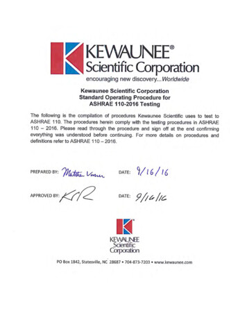
Hamilton SafeAire II Fume HoodGeneral InformationFume Hood ashBafflesAirfoil Sill5
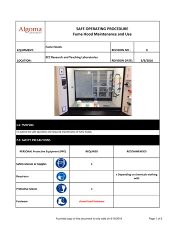
Hamilton SafeAire II Fume HoodInstallationFume Hood Superstructure InstallationSide Enclosure Panels1. Press down on two black catches and rotate side panelaway from fume hood. Lift side panel off of lower lipframe.4. Remove shipping screws holding the fume hood frameto the skid. Save four of these screws, No. 10 x 5/8”, tosecure fume hood to the work surface.5. Place the fume hood on the work surface taking care toprotect the work surface.Top ofFume HoodShippingScrewFrontPanelCatches6. Remove two shipping screws from the top of the frontpanel. These screws must be removed to allow futureaccess to the fluorescent lights.Side Panel7. Check the following items:Lower Lip!That the counterweight operates free of obstructions.!That the cables align properly in the pulleys.!That there is proper horizontal sash alignment andcounterweight balance.!That the sash does not bind in the sash guides.ShippingScrewsWeightPanNo. 10 x 5/8”Screws2. Remove two shipping screws that secure the counterbalance weight pan to the rear top rail.3. Remove screws from sash hold-down clips. Open thesash and remove blocking, being careful not to damagesill or baffles.Baffles can be installed at this time or after the fume hoodis in place on the work surface. See Page 13Work Surface8. Drill two each 1/8” diameter pilot holes at each sidestructural frame into the work surface and secure samewith four No. 10 x 5/8” screws saved from the shippingskid.9. Reinstall end panels.10. Caulk fume hood to work surface with silicone sealant.6hamiltonlab.com
Hamilton SafeAire II Fume HoodInstallationAssembly Instructions For Knocked-DownFloor-Mounted Fume HoodsGeneral – When receiving fume hood assemblies, inspect fordamage immediately. If damage is noted, request thedelivering carrier to note and describe damage on bill oflading prior to your signature. Notify carrier immediately andrequest inspection.#8 X5/8” PPHSMSOpen boxes and crates and examine for hidden damage. Ifdamage is noted, save containers and request an inspection.Move all components to installation area.#8 X3/4” PPHTCS1. Attach left-hand side assembly (2) to back assembly(1). Take back panel assembly and stand vertically, asshown, and slide into end assembly. (Angle flange of endassembly fits between back panel and horizontal membersof back assembly). Secure each corner with two #8 X 5/8”PPHSMS at mating holes on top and bottom corners ofjoined assembly. Repeat steps with right-hand end (3).Attach each baffle support with two each #8 X 3/4” PPHTCSthrough back panel into support. Do not over-tighten.#10 X5/8” PPHSMSTopBackRear Pulley BracketAssembly2. Attach top assembly (4), as shown at left, toback and ends with eleven (11) #10 X 5/8”PPHSMS. Top assembly fits underneath righthand rear pulley bracket assembly. Secureexhaust collar to rear rail.7
InstallationHamilton SafeAire II Fume HoodAssembly Instructions For Knocked-Down Floor-Mounted Fume Hoods (Cont.)3. Attach left rear pulley assembly (5) using three (3) #8 X 5/8”PPHSMS. Attach right rear plate assembly (6) using three(3) #8 X 5/8” PPHSMS. Slide 3” sheave (7), then 2” sheave(8) over threaded stud. Loosely fasten with 1/4-20 KEPS nut.Install right-hand cable retainer support (27) using two (2)#8 X 5/8” PPHSMS.4. Remove pieces of tape (9) holding top panel extrusion inplace. Lift header panel (11) and place bottom in right-handand left-hand baffle clips (10). (Short header panel - bypasshoods, does not have baffle clips). Bottom extrusion onheader panel faces outward. Fasten top of header panel toangle with #8 X 5/8” PPHSMS.#8 X5/8” PPHSMS8hamiltonlab.com
InstallationHamilton SafeAire II Fume HoodAssembly Instructions For Knocked-Down Floor-Mounted Fume Hoods (Cont.)5. Install four (4) baffles as indicated.Install baffles with notches down.Proceed from bottom to upper baffle (12,13, 14, 15). If remote control is includedwith hood, place intermediate baffle(14) in already installed remote controlbaffle arm (16). Lower and intermediatebaffles are the same size. Insert upperbaffle into collar extrusion per Detail“B”. Test remote control baffleadjuster for function.CollarTop PanelUpper BaffleUpperBaffleDetail “B”IntermediateBaffleLowerBaffleBottomBaffle6. Install rear top sash (17) in right-hand and left-hand rearsash guides. Sashes are installed from the top of the hood.Lower the sashes into the sash guides. The rear top sashmust be located above the stops located approximately halfway up the sash guides. Locate the front bottom sash (18) inthe front right-hand and left-hand sash guide. Remove thetape from the cable assemblies that are taped to each sashUncoil the cable and place on top of hood.Rear TopFront Bottom9
InstallationHamilton SafeAire II Fume HoodAssembly Instructions For Knocked-Down Floor-Mounted Fume Hoods (Cont.)Retainer Must 0.062”Not TouchSheaveFrontof HoodDetail “D”7. Before hood is pushed against wall, place top rear sashcable (19) over pulleys as shown in instructions. Bracebottom of sash about 6” above sash stops, with 2 x 4 orsimilar, to allow for a more manageable cable. Attachweight (20) to cable, Detail “C”. Fasten cable clamp (23)and two (2) 1/4-20 X 3/4 HHTCS (24), do not completelytighten screws. Repeat process with front bottom sashcable (21). Test sash level, alignment and travel. Make anynecessary adjustment. If necessary, fine tune weight pan.Fasten clamp screws tightly. Attach all cable retainers (22,25). Do not over-tighten retainers – allow 1/16” for pulleymovement. See Detail “D”. The nylon tape (26) at the cableloops at the ends of the sash pull is no longer necessary,remove and discard.BottomFrontBack of HoodRear Top8. Position fume hood in a permanent location. Have qualifiedpersonnel attach all required electrical devices andplumbing fixtures. Lower the side panel (27) onto the sideframe of the fume hood, engaging the frame’s lower lip.While pressing down on the two black catches, rotate theside panel and engage the frame’s upper lip. Gently applyadditional pressure to the panel and release the catches tosecure the panel to the hood.10hamiltonlab.com
Hamilton SafeAire II Fume HoodInstallationAssembly Instructions For Knocked-Down Floor-Mounted Fume Hoods (Cont.)9. Attach lintel panel (28) to front of hood. Engage top ofpanel with studs on top, inside of front access panel andfasten bottom of panel to angles on front access panelwith #8 X 5/8” PPHSMS. Drive screws as shown.10. Make sure hood is square and aligned.#8 X5/8” PPHSMS11
InstallationHamilton SafeAire II Fume HoodBaffle Installation and AdjustmentTwo choices of baffle designs are offered:1. Fixed.2. Remote exterior controlBaffle InstallationInstall baffles according to information on the next page.See label located on right front post for remote exteriorbaffle adjustment instructions.Baffle AdjustmentHamilton fume hoods have two baffle settings:A. Lighter-than-Air or high thermal loading.B. Heavier-than-AirBaffle position A is for lighter-than-air gases, or high heatloads. The top slot is open to maximize fume hood air flowin the upper portion of enclosure for efficient capture andexhaust of lighter-than-air fumes and hot gases.The baffle at position B provides maximum air flow acrossthe work surface for the collection and removal of fumesgenerated at the work surface and heavier-than-air gases.A – High Heat Loads or Lighter-than-Air GasesB – Heavier-than-Air Gases and Surface Fumes12hamiltonlab.com
InstallationHamilton SafeAire II Fume HoodFixed Baffle InstallationRemote Control Baffle InstallationInstalling Fixed BaffleInstalling Remote Exterior Control Baffle1. Place upper baffle into position by engaging top edge intofront exhaust collar extrusion. Lift baffle up and into uppersupport brackets to lock into position.1. Place upper baffle into position by aligning forked slotof remote arm straight up and down. Slide upper bafflethru fingers of remote arm and drop into top slot of uppersupport bracket. (Baffle should be in front of exhaustcollar extrusion).2. Place top edge of lower baffle into front slots on bottomedge of upper support brackets. Lift and lock baffle intothe slot of lower support bracket.2. Place top edge of lower baffle into front slots on bottomedge of upper support brackets. Lift and lock baffle intothe slot of lower support bracket.Exhaust Collar fleUpper Support BracketUpper Support BracketLowerBaffleLowerBaffleLower Support BracketLower Support BracketUpper Remote BaffleLower Fixed BaffleInstalling Lower Baffle – Fixed and Remote13
Maintenance and AdjustmentsHamilton SafeAire II Fume HoodAttaching Blower Enclosure to Fume HoodHardware included:1 Front panel1 Front panel – removable2 Side panels2 Front support brackets2 Rear support brackets1 Bag assembly53Tools required:#2 Phillips screwdriver4434442141112749864101191. Fasten support brackets (1) in front top of frame assemblyin holes provided. Use 1/4-20 x 3/4” hex head threadcutting screws (HHTCS) (2) furnished in bag assembly tofasten brackets.2. Fasten rear support (3) to rear top of frame assembly.Use No. 8 x 5/8” Phillips pan head sheet metal screws(PPHSMS) (4) furnished in bag assembly.3. Install right-hand (5) and left-hand (6) side panels tosupports using No. 8 x 5/8” PPHSMS (4).1484. Install front panel (7) to side panels with No. 8 x 5/8”PPHSMS.5. Subassemble thumb screws (8) and push retainers (9) toremovable panel (10).6. Insert hole fasteners (11) in larger hole in flange of sidepanels.7. Insert top flange of removable panel under and behindfront panel. Fasten thumb screws and tighten.hamiltonlab.com
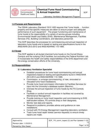
Hamilton SafeAire II Fume HoodFume Hood MonitorInstallationMinihelic Gauge InstallationProper fume hood operation is key to laboratory safety,comfort and energy management. OSHA requires thatlaboratories take measures to ensure proper and adequateoperation of fume hoods. Recommendations include the useof a continuous air monitoring device. The ANSI Z9.5 andNFPA 45 standards reinforce these requirements.Fume hood monitors have the ability to monitor true fumehood face velocity using thermal sensors located in theinstrument. The thermal sensors are exposed to cleanlaboratory air only. They can be surface-mounted in minuteseliminating the need for expensive panel cutouts.Each model is equipped with indicator lights that illuminatebased on a predetermined set-point. An audible 85dBpiezoelectric alarm sounds and a red indicator lightilluminates to warn of potentially dangerous low air flowconditions.Sensor block and sensortube, two required eachConnect to low sideof Minihelic GaugeThick-wall vinyllaboratory tubing,cut to lengthConnect tohigh side ofMinihelicGaugeMinihelic Gaugerange 0”-3”W.C., reads filterpressure dropFront PostFume hood monitors are shipped with operation manuals.Replacement filter sets consist of one rough and oneHEPA filter.Filter InstallationThe HEPA exhaust filter is an optional item.Exhaust filter installation for product numbers54L29600, 54L29700, 54L29800 and 54L29900Product Number 54L30200 – Filter set for 54L29600 or 54L29800.Product Number 54L30000 – Filter set for 54L29700 or 54L29900.Pre-Filter CoverFront ofFume HoodThe pre-filter cover facesforward on RestrictedBypass and Constant VolumeBypass fume hoods.Securely attach the filter inlet collar to fume hood exhausttransition using same method as followed in the duct system.Filter outlet may be attached to duct using flexible connectoror same as inlet connection.15
Warning and Operating InstructionsWarning and Operating InstructionsHamilton SafeAire II Fume HoodOperating InstructionsFailure to follow these instructions could result in physicalinjury or illness.Caution: Do not use fume hood for perchloric acidprocedures.1. Do not use this fume hood unless you have receivedproper training from the owner’s industrial hygienist orsafety representative.Refer to operationinstructions label onleft side of sash glass.WarningThis product is intended for use with certain chemicals thatcan cause serious injury or illness through inhalation orphysical contact. While this product is intended to minimizeexposure to certain hazardous chemicals when selected,installed and operated properly, its performance and thesafety of the user is affected by a number of factors. Theseinclude the HVAC system, the specific chemicals andprocesses being used, proper operation and the condition ofthe room.Before using this fume hood, consult the owner’s industrialhygienist or safety representative to ensure:1) The specific fume hood alarms, controls and the HVACsystem have been properly selected and are operatingcorrectly;2) The fume hood has been tested after installationand routinely thereafter to ensure the fume hood isproviding the proper containment for the specificchemicals and processes being used;3) There has been appropriate training on the correct useof the fume hood and handling of the specific chemicalsand the fume hood operating instructions have beenreviewed;4) Any personal protective devices that are required areproperly selected and provided;5) The fume hood is being operated at the appropriateface velocity. The fume hood should never be operatedwith the sash in the full open position.2. This fume hood is not intended to be used with allchemicals or all chemical processes. Consult the owner’sindustrial hygienist or safety representative to determinewhether the fume hood is appropriate for the chemicalsand processes to be used.3. Verify that the fume hood exhaust system and controlsare operating properly and providing the necessary airflow. If in doubt, the owner’s industrial hygienist or safetyrepresentative should be consulted. It is recommendedthat the fume hood be equipped with an air flowmonitoring device. Before using the fume hood, verify thatthe monitor is operating properly by testing the monitor.4. The fume hood should not be operated with the sash inthe full open (setup) position. When the fume hood is inuse, the opening of the sash glass should be kept at aminimum. On a vertical rising sash, the sash glass shouldbe no higher than 18”. The sash should remain closedwhen the fume hood is not in use.5. Place chemicals and other work materials at least six (6)inches inside the sash.6. Do not restrict air flow inside the fume hood. Do not putlarge items in front of the baffles. Large apparatus shouldbe elevated on blocks. Remove all materials not neededfor the immediate work. The fume hood must not be usedfor storage purposes.7. Never place your head inside the fume hood.8. External air movement can affect the performance ofthe fume hood. Do not operate near open doors, openwindows or fans. Avoid rapid body movements. Do notopen the fume hood if there are cross drafts or turbulencein front of the hood. Do not open the sash rapidly.9. Wear gloves and other protective clothing if contact withcontaminants is a hazard.10. Clean spills immediately.11. If fumes or odors are present, stop operating the fumehood, close the sash and contact the owner’s industrialhygienist or safety representative immediately.12. It is recommended that this fume hood be tested andcertified annually by the owner according to applicableindustry and government standards.16hamiltonlab.com
Hamilton SafeAire II Fume HoodMaintenance and AdjustmentsGeneral Maintenance of Fume HoodsFume Hood Inspection ProceduresFume hood maintenance procedures consist primarily ofcleanup, adjustment, lubrication, and replacement of worn,damaged or non-functioning parts. Lubrication of sashguides, cables, pulley wheels, and other working partsshould be accomplished as required and replacement ofbroken, worn, or non-functioning parts as needed. Thefollowing items should be inspected and serviced at leastsemi-annually:Safety considerations require that a schedule of inspectionand documentation be setup for every laboratory fume hoodat least annually.!Liner and baffles for condition and cleanliness.!Low air flow detectors.!Service fixtures and lights.!Pulleys and belts.Sash operation and counterbalance cables includinga complete visual check of the entire system.!Make sure there is a 1/16” clearance between cablekeepers and pulley sheaves.!!Velocity and pressure sensing detectors.!Low or no flow alarms, both visible (lights) and audible (hornsor bells).!Signal transmission for alarms designed to activate signals atmore than one location.!Instrument verification of fume hood face velocity anddetermination of usage by observation and interview.!Ductwork and blower.An inspection record should be maintained. This record maybe in the form of a label attached to the fume hood, or a logheld by the laboratory director or health safety director.Inspection procedures should include instrument verificationof fume hood face velocity and a determination of usageby observation and interview. These procedures shouldalso consist of a physical examination of liner conditionand cleanliness, baffle and sash operation and condition,counterbalance cables, light operation and condition, andservice fixture function.Inspection results should be recorded and reported to theproper authority for any required action.Special purpose fume hoods such as those used withradioactive materials or perchloric acid require additionalinspection procedures to cover special equipment andrequirements.Options, such as low air flow detectors, when installed,should be inspected at least annually. Where extremehazardous or corrosive conditions exist or when filters arepresent in the system, the inspection frequency should beincreased appropriately. Velocity and pressure sensingdetectors should be tested at each inspection. Low-flowof no-flow alarms of the visible (lights) or audible (horns orbells) type should be tested for correct operation at least ateach inspection. Signal transmission for alarms designed toactivate signals at more than one location should be verifiedat each location during each inspection. Frayed or brokenbelts should be replaced promptly.Cleaning Fume Hood InteriorsWarning (For Perchloric only)Use only fluorocarbon grease on blower since any other type isto be considered potentially dangerous.WarningFrayed or broken cables should be replaced to avoid personalinjury or damage to fume hood. Not all cable manufacturer’scables are the same quality and cycle life.Fume hood liners are maintained by an occasionalwashdown with detergent and warm water. Stains and saltdeposits can be removed with a weak acid solution (5%) oran appropriate solvent – DO NOT USE ACETONE. Removebaffles for access to all surfaces. See Page 10 for removaland installation procedures.The use of organic chemicals or materials in a specializedperchloric acid fume hood with a stainless steel interiorshould be avoided.Cleanup should be accomplished by, or under thesupervision of, a knowledgeable technician and shouldinclude removal of all baffles for cleanup of all interiorsurfaces.Flush all spills immediately using neutralizing compounds asrequired and clean thoroughly. Use good housekeeping inlaboratory fume hoods at all times.17
Maintenance and AdjustmentsFluorescent Light Tube Replacement – Bench Top andHi-Line Fume HoodsHamilton SafeAire II Fume HoodInstallation of Access PanelTwist the corners of gasket towardscutout before insertion. Replace thepanel and work the entire periphery ofthe gasket to be sure that the gasketis completely snapped into position.Gasket should be smooth and tight whenproperly seated.The fixtures used within fume hoodsare needle valve type, and if they wear, stainless steel coneand seat replacement kits can be ordered through your salesrepresentative. It is necessary to remove the handle from thevalve and then remove the valve mechanism. This can bedone through the access panels (shown above) if fixtures aremounted in the superstructure, or from inside the cupboard ifthe fixtures are deck mounted.Removetwo screws1. Remove sash enclosure if applicable.2. Remove two screws securing bottom of front panel tofront corner posts. Pull front panel up to disengage fromstuds and remove panel.Access to the valves by removal of the exterior end panels(Step 1 on Page 6) permits seat replacement without theneed to remove the valve. This approach is recommendedwhen ends are exposed and accessible.3. Squeeze bottom edge of lamp housing to disengage fromgalvanized channel. Rotate lamp housing up to exposebulbs. Replace bulbs with same type as in unit. Turn onlight switch to verify connections.Access to service fixture valves on fume hoods withoutaccess panels is obtained by removal of the exterior endpanels (Step 1 on Page 6) when fume hoods are freestanding.4. Reverse Steps 1-3 to return fume hood to usablecondition.Fume Hood Service FixturesAccess Through Front PostsLift up and pull outScrewsInsert screwdriver andwedge out panel andgasket assemblyFront Corner PostRemoval of Access PanelIndex Button,Screw, Control Knob,and Retainer FlangeWhen ends are notaccessible, access isgained through the frontposts. To remove frontpanel, unscrew indexbutton, control knob,and retainer flangefrom fixture handle rod.Remove two screwsfrom post as shownabove, lift up andoutward to remove post.Electrical fixtures areconnected to post withflexible conduit and canremain attached.18hamiltonlab.com
Hamilton SafeAire II Fume HoodMaintenance and AdjustmentsFramed Glass and Cable ReplacementSpecial parts, options, and accessories should bemaintained as required.Inner SashMouldingSashes occasionally require service. The glass may fog dueto the condensation of chemical vapors, and such materialsshould be removed promptly by washing with water anddetergent to prevent etching of the glass.WarningIf cable is frayed or damaged, it MUST be replaced toavoid personal injury or damage to the fume hoodFramed Glass and Cable ReplacementSash Frame3. Press the four sections of the inner sash moulding stripover the sash frame edge.ClampTop ofFume HoodCableInner SashMouldingSash FrameLaminatedSafety Glass1. Hold the sash in the closed/down position by clampingthe sash counterbalance cable to the top structural framemember. In some situations, access to the top of the fumehood may be gained by:! Removing end panel if end of fume hood is clear –See Page 6.! Removing front louver panel – See Page 20.! Removing blower enclosure panels – See Page 16.4. Place the new sash glass onto the inner sash mouldingand hold in place.LaminatedSafety GlassInner SashMouldingLaminatedSafety GlassOuterMouldingOuter MouldingInner SashMoulding5. Press the outer moulding strip into the groove of
designed fume hood be set aside for exclusive use with this material. The fume hood is equipped with a cold water spray device for washdown of the interior surfaces. A trough is placed across the back of the fume hood for collection and disposal of washdown waters. Operating personnel should be well trained in the proper handling techniques and be