Transcription
J amestownM etalP roductsFume HoodMaintenance &Operation ManualCopyright March 2002, Jamestown Metal Products, All rights reserved
J amestownM etalP roductsMaintenance and Operation ManualTABLE OF CONTENTSFume Hood Applications .Safety .Aerodynamic Principles & Safety .Fume Hood Cleaning .Basic Maintenance .Perchloric Fume Hoods .HOPEC Fume Hoods .Velocity Alarms .Trained Personnel Procedures .Fume Hood Safety Labels .Warranty .Hood Features & Label .Air Flow Chart .“Knock-Down” Overview / Bench .Inventory & Check-off List .Assembly .Component Diagrams .JAMESTOWN METAL PRODUCTS178 BLACKSTONE AVENUEJAMESTOWN, NEW YORK 14701Phone: 716-665-5313Fax: 716-665-5121Website: www.jamestown.comEmail: info@jamestown.comPag e 1234678910121314151617181927
J amestownM etalP roductsFume Hood ApplicationsIf your fume hood is to protect you, it must be designed to be compatible with the typeof work that will be performed. For example, working with radioisotopes or carcinogensrequires a fume hood with a non-absorbent lining (usually stainless steel) designed to be easily decontaminated.Today, energy efficiency is a high priority. A HOPEC (Hand Operated Positive EnergyControl) fume hood is an energy saving and extremely safe alternative fume hood design.Only a specially designed laboratory fume hood should be used for perchloric acid procedures. This fume hood type should be clearly labeled and its use restricted to only perchloric acid procedures.Other specialized applications may require explosion proof fixtures, electrical receptacles, non-combustible liner materials or fire extinguisher systems.Never use a fume hood that has not been designed for the type of procedure beingperformed!To be sure your fume hood is the right one for the work you are doing, you may contact your local jamestown representative or give us a call at 716-665-5313. Our website atwww.jamestown.com is an excellent source for frequently updated technical information andreference materials about fume hoods and other laboratory equipment. You can also emailus for information at info@jamestown.com.Common Fume Hood TypesBench Fume Hoods:Most common hood type used for general chemistry procedures. Specialized versions include; ADA Bench Hoods foraccess by handicapped personnel, OS Height Hoods withlarger interior height for work requiring intermediate sizedequipment, HOPEC, Radioisotope and Perchloric hoods asdescribed above.Walk-In Hoods:A floor-to-ceiling fume hood for chromatography, distillation,pilot plant mock-ups, vat drug preparations and other procedures requiring large equipment inside the containmentchamber.Pag e 2JAN 2002
J amestownM etalP roductsYour Safety is our Top Priority!Your new Jamestown Fume Hood is the result of extensive research and developmentto design fume hoods that are economical, efficient and the safest on the market. Thedesign, materials and construction are periodically reviewed to assure an even better andsafer product.But you, the fume hood operator, are the single most important safety feature in thelaboratory.No matter how safe the fume hood system is designed to be, the operator must followcertain procedures for it to work safely and efficiently.We urge you to become familiar with the recommended fume hood practices outlinedin this booklet in addition to those published by your organization but, most important, make ahabit of applying them every day. We think you’ll agree it’s the best way to help ensure asafe, healthy work environment for you and your co-workers.Our fume hoods, as manufactured, are the safest in the industry but we need yourcooperation to keep them that way in your environment.Maintain an appropriate attitude towards safety.Every laboratory should have written procedures for handling emergencies such as:zzzzzz“Runaway experiments”FireExplosionPower failureBlower failureService fixture failureThese procedures should be posted in a prominent place and all laboratory workersmust be familiar with them in order to react appropriately in an emergency situation.“What if.” drills should be run when a fume hood is first installed, or when staff or procedures change. In surprising numbers of instances, misplaced fire extinguishers, inaccessible fuse boxes and blocked exits are only discovered during such a mock emergency.Safety drills are not only for the new employee. Long-time employees need reinforcement of safety procedures also.Pag e 3
J amestownM etalP roductsAerodynamic Principle & SafetyA Jamestown Fume Hood is designed to contain harmfulcontaminants and vent them out of the work space. It provides an enclosed area that has a protective air barrierbetween you and the harmful materials you work with. Thedirectional air flow caries the contaminants towards the rearof the hood and dilutes them with large quantities of air tosafely exhaust the hood.If anything disrupts this air flow, the fume hood’s ability toprotect you will be seriously reduced.Follow these important safety procedures to ensure properair flow within the hood:z Use the illumination provided and be sure the hood is operational.Always turn on the interior light for proper illumination of the work area. Verify theexhaust system is working properly and that air is entering and flowing through the fume hoodbefore starting fume producing activities. Be certain you know how to turn on the hood. Inmany facilities it is automatically controlled by the HVAC system. In others, control of eachhood is local at an on/off switch located on or near the unit.Verify you have a proper face velocity at or above 100 FPM through the sash openingyou select before beginning fume-evolving activities. To confirm that your fume hood’sexhaust system is working properly we recommend equipping the fume hood with an air flowmonitoring device. Correct face velocity can be assured by periodically checking air flow witha hand-held velometer. Refer to page 10 for more specific information regarding velocityalarms.z Verify proper baffle settings.Safe and proper fume hood operation requires an understanding of the function offume hood baffles as well as the HVAC system. Operators should not adjust the baffle settings once they have been balanced by qualified HVAC personnel.z Set-ups and apparatus should be as far back from the fume hood face as ispossible for safety and optimum performance.When you stand in front of the hood with the sash open, the airflow passing your bodycreates a zone of low pressure directly in front of you extending in about four inches. Sincecontaminants can enter this area of turbulence from inside the hood, all experiments andequipment should be placed at least six inches behind the plane of the sash, behind the protective air barrier. The further back you can place the source of contaminants, the greaterprotection a hood can provide. However, don’t place items you’re using so far back that youneed to lean your head or face into the hood during procedures.Pag e 4JAN 2002
J amestownM etalP roductsAerodynamic Principle & Safetyz Allow air flow at the work surface.Do not block the lower rear baffle slot of the fume hood. Large, bulky objects shouldnot be placed directly on the fume hood working surface. Block such objects up two or threeinches to permit a flow of air underneath and into the lower rear baffle exhaust opening.z Avoid rapid movement in front of the fume hood face.Avoid rapid movement and excessive personnel passage in front of the fume hood. Airdisturbances so created may draw fumes out of the hood.z Operate the hood with the sash closed as much as possible.While working at the fume hood, open the sash only as far as you need to for accessto your work area. The lowered sash increases the distance between your breathing zoneand the area where fumes could escape into the lab. It also offers added protection by actingas a solid barrier against splashing chemicals or debris from explosions or runaway experiments.z Never store chemicals in the hood.Use of laboratory hoods as storage enclosures for corrosive, toxic or flammable materials may jeopardize fume hood performance and create unnecessary hazards. Limit materials within the hood to those required for immediate use.Today, virtually all packaging is designed to safely contain reagents. Any leaky package should be disposed of immediately and appropriately, not stored in the fume hood. Cleanup spills as soon as possible. Always use grounded electrical equipment.z Avoid extreme heat.Never permit the temperature of the sash surface to reach or exceed 160o F, as laminated safety glass cracks at this temperature. We recommend our standard tempered glass,instead of safety glass, as it is stable up to 400o F.Black hood liner material, such as epoxy, can also absorb invisible infrared light fromheated objects and may crack under heat stress.z Maintain lab safety instructional materials.Design a videotape outlining your organization’s safety procedures, and be sure newemployees view this tape. Jamestown can supply a video of this nature, but it lacks specificchemical information and procedures that only you, as the end user, can provide.In summary, safety in fume hood operation involves three concepts:z Following accepted procedures.z Avoiding questionable procedures.z Maintaining the structural integrity of the equipment and the safetyawareness of the laboratory staff.Pag e 5
J amestownM etalP roductsClean Fume Hood Safe Fume HoodPeriodic cleaning of the fume hood interior.A neat and clean fume hood is not only aesthetically advantageous but alsosafer and easier to “shut down” in case of an emergency! Clean up any chemical spillage assoon as possible. All worktops recommended by Jamestown are “dished” to help containspills. Use only cleaning materials recommended for use in conjunction with the proceduresbeing conducted within the hood. By keeping the fume hood clean, the chemical residues ofyour procedures will have less time to potentially damage the internal components, therebyminimizing the risk of a possibly catastrophic failure of a key hood component.The following are basic cleaning and maintenance procedures which can be performedby the fume hood operator. Confirm that the cleaning agents being used will not react withthe chemicals being used in the hood.CLEANINGz Polyglass Liner:Can be cleaned with mild soap and water. For persistent stains use our polyglass linercleaner (part number: SP26), acetone (with a thorough wipe-down afterwards due to flammability), JSS #22 Remove or #400 automotive sandpaper.z Sash Glass:Can be cleaned with a commercial glass cleaner.z Painted Steel Surfaces:Can be cleaned with mild soap and water, ethyl alcohol or commercial glass cleaner.z Epoxy Liner and Worktops:Can be cleaned with mild soap and water, solvent or commercial glass cleaner.z Plumbing Fixtures:Fixtures are coated with a corrosive resistant coating. Clean with mild soap or detergent only. Do not use an abrasive cleanser.Pag e 6JAN 2002
J amestownM etalP roductsBasic MaintenanceSchedule frequent maintenance checks of the condition of sash components,exhaust system and load bearing parts.The very nature of the materials used in a fume hood, harmful or corrosive chemicalfumes, can lead to deterioration of the fume hood’s components due to the long-term effectsof any chemical reactions. Any metallic load-bearing member inside the hood needs to bechecked frequently for corrosive deterioration. Be aware of vertical sash counterbalance systems utilizing cables that can release the sash in guillotine fashion of the cable snaps.Horizontal sashes have been known to break loose and cave into the hood when corrodedsuspension systems give way. Internal back baffle panels have broken free of their deteriorated hanger brackets.Newer style hoods by most manufacturers combat some of these problems by eliminating or chemically coating the metal parts in question. Jamestown has incorporated a chaindriven sash counterweight system that eliminates the possibility of fraying cables or fracturedpulleys.BASIC MAINTENANCEz Sash:A properly balanced sash, at 50% open, should not move up or down without operatorassistance. If the sash is out of balance, do not attempt to adjust it yourself. No portion ofthe sash mechanism is user adjustable. Contact the appropriate maintenance department foryour facility or a Jamestown representative.z Velocity Alarm:Test the velocity alarm daily by placing your finger over the thermistor reference holeon the front cover plate. Face velocity readout should quickly drop to zero and the audioalarm should sound.z Fans and Ductwork:Be sure your maintenance staff schedules frequent checks of the fume hood’s fansand face velocities. Because the ductwork system is exposed to toxic and corrosive fumes, itis a vulnerable link in your lab’s exhaust system and requires vigilant monitoring.Pag e 7
J amestownM etalP roductsInstructions for Perchloric Fume HoodsPerchloric acid, HCIO4, is unforgiving if not handled correctly. Its acidity is nominalbut each molecule essentially carries around four extra oxygen atoms which like to react,burn, or explode; whichever is easiest.Concentrated perchloric acid should never be heated. Old bottles of acid should bediscarded as hazardous waste. It can be expected to react with most types of plastics,except PVC or Teflon.Perchloric acid may form contact explosives with some shaft bearing lubricants. Onlyfluorocarbon lubricants should be used on perchloric acid fume hood exhaust fans. We recommend the exhaust streams for these hoods be dedicated and not mixed with other fumehood exhaust streams.Periodic cleaning of the perchloric acid fume hood interior.Due to the explosive and reactive nature of perchloric acid salts that accumulate in thehood and ductwork, the washdown system in your fume hood should be used after every useor at minimum, once a day. In continuous use applications washdown the hood at week’send.Discontinue experiments in the hood and remove devices that could be damaged bywater. Switch the exhaust system off, then turn on the washdown bar to flush water throughthe hood system. The rear baffles should be flushed for at least five minutes. Next, policethe hood interior with a sponge, thoroughly rinsing the sponge to remove chemical residue.Be sure the hood interior is completely dry before replacing your equipment.In most cases, the fume hood ductwork washdown system interfaces with the hoodwashdown system. Check with the appropriate party in your facility to determine how yoursystem operates. Test the system with an empty hood before attempting a washdown procedure.Other special considerations for perchloric acid hoods:Any components used in conjunction with perchloric acid experiments, such as distillation racks, should be fabricated from stainless steel not aluminum.Pag e 8JAN 2002
J amestownM etalP roductsInstructions for HOPEC Fume HoodsHOPEC (Hand Operated Positive EnergyControl) fume hoods look slightly different than ourISOLATOR hood but they work in much the samefashion. It also addresses concerns such as ADA(Americans with Disabilities Act) and LCV (LowConstant Volume). The main difference being:z The fume hoods are designed to be operated with at least 50% of the combination sash closed.This condition is achieved by either:1. Having the vertical portion of the sashcompletely closed and the horizontal panel(s) openfor operation.2. Having the horizontal panels fully closedand the vertical portion of the sash raised not morethan 15”.z The hood is deeper than an ISOLATOR hood due tothe design of the front airfoil. The airfoil is bright yellow toremind the operator to keep all experiments and equipment atleast six inches behind the plane of the sash.Pag e 9
J amestownM etalP roductsVelocity AlarmsAir is drawn into the fume hood by its exhaust system which creates a pressure difference between the surrounding room and the hood interior. The speed of the air passingthrough the sash is called the face velocity. Proper face velocity is required to protect theoperator and surrounding area from harmful components inside the hood.There are two different models of velocity alarms available to choose from.Alnor Velocity AlarmThe Alnor AirGard 335 Velocity Alarm has audible and visual indicators. In dangerous situations a continuous audible alarm will alertthe operator. An electronic bar graph moves back and forth throughuniversally recognized zones, red - yellow - green, as the velocitychanges. Corresponding large colored LEDs also illuminate. A digital display can be enabled to view velocity quantitatively.Jamestown Digital Velocity AlarmThis unit will give the fume hood operator a continuous digitalreadout of fume hood face velocity. If the face velocity drops below apreset alarm set point an audio alarm and flashing red LED display willalert the operator of dangerous situations that may arise.Always verify you have a proper face velocity before beginning fume hood activities.Remember to test the velocity alarm every day and that everything is running correctly. If it isnot, make sure the proper maintenance department for your facility is contacted immediately.Do not use the fume hood until this condition has been corrected.P ag e 10JAN 2002
J amestownM etalP roductsVelocity Alarm Calibration InstructionsCalibration of Jamestown Digital Velocity Alarm1. Power up the alarm and set the switch to “Run”, calibrate as follows:a. There are three calibration potentiometer holes located on the alarm face plate.b. With the fume hood and make-up air off, turn the left most potentiometer (RP2) untilthe digital counter just moves off zero. Now turn the potentiometer back inthe other direction until the reading barely returns to zero.2. Turn the fume hood and make-up air on. Using the sash or damper adjustment, or both,set the face velocity at the desired sash setting to the desired alarm set point (10 to 100FPM) using a velometer, not the velocity alarm.3. Remove the alarm cover and select the one of the ten numbered DIP switches (SW1) thatcorresponds to your alarm set point. Move the DIP switch to the right (On position).Replace the alarm face plate.4. Turn the set screw on the center potentiometer (RP1) until the alarm signal activates.5. Using the sash or damper adjustment, or both, set the fume hood velocity to 100 FPMusing a velometer, not the velocity alarm. Adjust the rightmost potentiometer (RP3) untilthe digital readout is 100 FPM. Alarm is now calibrated and ready for use.Alarm is now set to digitally read the average face velocity and activate the alarm if thedesired minimum value is not held. Note: Audio alarm can be muted by activating the Muteswitch, but the warning light cannot be turned off.Calibration of Alnor Velocity AlarmPlease refer to the AirGard 335 owner’s manual for proper calibration of this device orvisit their website for manuals and information at www.alnor.com.P ag e 11
J amestownM etalP roductsProcedures for Trained PersonnelThe following maintenance items should be undertaken only by building maintenance,trained fume hood or HVAC installation personnel.z Periodic inspection of the ductwork system.At least twice a year the exhaust duct and fan integrity should be inspected. Check forlocalized corrosion, broken fan parts and debris clogs. If items such as tissue, paper or foilare used in the hood, it is possible for them to be drawn into the baffle/duct system, formingblockages that reduce air flow.z Periodic smoke tests.At least twice a year we recommend running a smoke test on each hood. Smokesticks and other testing materials are available for purchase from Jamestown.z Periodic testing of the velocity alarm.At least once a year test the accuracy of the velocity alarm by using a hand heldvelometer.z If the sash becomes “cocked”.If the contact between the airfoil and the sash handle is not continuous and flush,loosen both sprockets, on the side that is not making contact with the airfoil, from axle contactby loosening the 3/32” Allen screws (two per sprocket). Close the sash fully making sure it isflush against the airfoil. Verity the chain is properly seated on the sprockets. Re-tighten theAllen Screws on each sprocket.z If the sash is out of balance.Note: If the sash is a combination sash, first verify all horizontal sliding panels are in place.Contact your Jamestown representative, who can supply additional small weights tobalance the sash. Attachment instructions will accompany the counterweight pieces.z If the sash does not operate smoothly or makes noise.Contact your Jamestown representative immediately for an inspection. The chainmechanism should not require lubrication. This may be a symptom of a more serious problem.z If the sash glass breaks.Replacement sash units may be ordered through your Jamestown representative. Donot attempt to replace the glass without first requesting a copy of the instructions for sashreplacement.P ag e 12JAN 2002
J amestownM etalP roductsFume Hood Safety LabelsIf the instructional label on your fume hood is missing or is illegible, we have, for yourconvenience and safety, reproduced it on this page. Use a copy of this as a temporary safetymeasure but be sure to contact your local representative or Jamestown Metal Products for animmediate replacement.P ag e 13
J amestownM etalP roductsProduct WarrantyJamestown Metal Products for a period of three years, from date of shipment, warrantthat furnished products shall be free from defects in material and workmanship. JamestownMetal Products shall also warrant the products to be as represented and will repair or replaceany part, under normal use, if examination discloses it to have been defective within the warranty period.Jamestown Metal Products for the life of the sash mechanism warrant that furnishedproducts shall be free from defects in material and workmanship. Sash mechanism refers tothe #35 case-hardened steel chain, sealed bearings, drive axle rod and chain attaching pointsat both sash handle and counterweight.Drive Axle RodSteel ChainSealed bearingsAttaching PointsP ag e 14JAN 2002
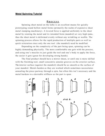
J amestownM etalP roductsHood Features & Identification LabelObservation GlassElectrical and Plumbing Fixture StationsSide PanelAccess PanelUpper and Lower AirfoilsBaffles w/ Lower AdjustableSashISOLATOR FUME HOOD716-665-5313Manufactured by Jamestown Metal ProductsJamestown, New York 14701Model:Phase:Cycles:Max KWS:F-100-72150/62.4Serial No:Equip No:Voltage:Max Amps:P ag e 15263 1 0112557YS12020
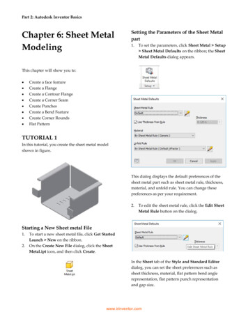
J amestownM etalP roductsAir Flow ChartBench HoodVertical SashName :Organization :48” SizeO O O ODate :O O O OLocation :Bench HoodHorizontal SashRoom :Fume Hood Model :48” Size1/2AreaSize :O OSash :O OHoriz. sashes use 50%area of appropriate sizehood. Use upper or lowerrow below to show this.Type :Identification Number :Walk-In HoodVertical SashREADINGS72” SizeOOOOOOOOOOOOF.P.M. Average :Total F.P.M. - / Total Readings - Total C.F.M. :Only readupper sashOnly use upper vert. sashopening to measure F.P.M.1F.P.M.3F.P.M. Average - x ( *Sq. inches / 144 ) F.P.M.*Sash opening height x width5F.P.M.7F.P.M.9F.P.M.11 F.P.M.13 F.P.M.15 F.P.M.2468F.P.M.10 F.P.M.12 F.P.M.14 F.P.M.16 F.P.M.36” Hood48” Hood60” Hood72” HoodF.P.M.Each AreaApprox.12” x 12”F.P.M.F.P.M.P ag e 1696” HoodJAN 2002
“Knock-Down” Overview / Bench HoodA bold number system is used to follow the steps for assembly. A subscript system is also in place next to the various components throughout themanual to aid the reader in recognition of those components with a visual reference provided in the rear of this manual.Care has been taken on the “strategical” presentation of assembly, shying away from the “tactical” assembly, as you can give instructions on how togo from point A to point B but there are many methods and preferences to thisgoal.A component and check-off list has been provided, as the heading suggests, to inventory the shipped crate for completeness and to mark off the components as they are used to assure the hood is properly assembled.EXAMPLE8. Using #10 x 3/4”13a screws with base3 attachments, screw in the bottom, middle andlower baffle units to the center bracket supports and side bracket supports [ 8 a ]. Attach thecenter angled bracket2. Check that the baffle units are secure and flush against the bracketsupports by visual inspection or physically feeling behind the baffles [ 8 b ].*Paragraph number ( 8. ) refers to corresponding picture box(s).*Subscripts ( 13a, 3, 2 ) denote the component number on pages 27 & 28 for visual reference.*Lettered outlined number ( [ 8 a ], [ 8 b ] ) signifies specific picture box.8aCenter angled bracketEnsure flush between unitsUpper baffleMiddle baffle8bLower baffleP ag e 17
J amestownM etalP roductsInventory & Check-off ListPack List #1 Upper baffle Middle baffle Lower baffle Back frame liner Observation glass/ smoked Sash Side panels x 2 Lower adjustable bafflePack List #2 Axle rods x 2 Lower airfoil Upper airfoil Ceiling Soffit (If included)Pack List #3 Fascia panel x 2 End frame assembly x 2Pack List #4 Top frame assembly Back frame panels x 2Pack List #5 Counterweight/ J-plate & insertPack List #6# JMP Part Number #10 x 3/4” screws13a x 50 #02300447 #10 x 1/2” screws13b x 50 #02300443 #8 x 1/2” screws13c x 20 #02300434 U-Tapped clip1 x 2 #02150414 Screw base3 x 50 (Integral with screw caps) Screw caps6 x 50 / white #02750410/ black #02750409 Viewpass bracket set x 2 Center baffle support x 3 Side baffle support x 6 Nylon bolt and nut10 x 1 #02750407 Baffle knob & bolt8 x 2 / knob #02450400/ bolt #02100415 Center angled bracket2 #40038408 Plug caps, various11 x 40 Chain x 2 #02800493 Sprockets14 x 4 #02800427 Spacer collar7 1/2” dia. x 4 #02800438 Connecting chain link9 x 4 #02800496 Threaded chain connector16 x 2 #02500496 Rubber bumper / black5 x 2 #02750413 PVC pushpin12 x 50 #02750490 Sash stop15 x 2 #40039200 *Assorted electrical components *Assorted plumbing components*Varies with options ordered.P ag e 18JAN 2002
J amestownM etalP roducts“Knock-Down” Assembly1. Set and level fume hood worktop and base cabinets per manufacturer recommendations.2. Place counterweight at rear of worktop such that the hanging holes are topmost andweight is leaning against the wall with smooth side of J-plate facing to the front.3. Attach the 2 back frame panels. The slotted corners are the top parts of the frame. Use#10 x 1/2”13b screws to attach.4. Attach the liner to the smooth side of the back frame panel. Line up the hole slots anduse the PVC pushpins12 to secure. Top of the back frame is with the center holes skewedto the left. Place the back frame against the wall in front of the counterweight.5. Take the 2 end frames, liner inward - right side up, attach them to the back frame panelusing #10 x 1/2”13b screws [ 5 a ]. You can use vice grips to hold the back frame and endframes in place to keep them stable to assemble [ 5 b ]. Use #10 x 1/2”13b screws to attach.43Use pushpins to secure all sidesSlotted corners face upward#10 x 1/2” screwsCenter holes skewed to left5a5bEnd frame placementP ag e 19
J amestownM etalP roducts“Knock-Down” Assembly6. Assemble the baffle bracket supports. For side support use short 2 hole for the bottom,long 2 holes for the middle and 3 hole for angled top [ 6 d ]. For the center use the codepunched center baffle brackets. T-punched bracket for the top portion, U-punched for themiddle portion and L-punched for the lower portion [ 6 a ]. The reason for the offset holes isfor the angled center bracket supports so when attached the holes are centerline with thehood. Then attach the side bracket supports for the viewpass glass [ 6 c ]. Only secure theback brace on the top loosely leaving the bottom hole free. This will provide easy insertionlater on with the viewpass. #10 x 3/4”13a screws are to be used. Be sure to attach sidesupports with angle facing forward [ 6 b ].7. Assemble the lower baffle section. Use the lower baffle and lower adjustable baffle.Combine both units correctly using adjustable baffle knob and carriage bolt8.8. Using #10 x 3/4”13a screws with base3 attachments, screw in the bottom, middle andlower baffle units to the center bracket supports and side bracket supports [ 8 a ]. Attach thecenter angled bracket2. Check that the baffle units are secure and flush against the bracketsupports by visual inspection or physically feeling behind the baffles [ 8 b ].6aAngles forwardT bracketBack brace loose6b6cU bracketL bracketCenter angled bracket8a6dEnsure flush between units3 hole topUpper baffle2 hole middle, longMiddle baffle8b2 hole bottom, shortLower baffleP ag e 20JAN 2002
J amestownM etalP roducts“Knock-Down” Assembly9. Place top hood portion into place with lightbox to front of fume hood [ 9 a ]. Around thesides and back of top frame use #10 x 1/2” screws13b to attach to back and end frame.After the top is secured use a white nylon bolt and nut10 to attach the center angledbracket2 to the fume hood top [ 9 b ].10. Slip one end of the axle rod, angling it, through one of the side bearings4 [ 1 0 a ]. Slipon 2 collar spacers7 on the axle rod. Slip the rod through a little further to be able to get inthe other end. In the process be sure to attach the sprockets14 as they have to be in placejust after the insertion of the axle rods. Be sure the sprocket teeth side are faced towardthe interior of the hood [ 1 0 b ]. Position the axle rods so as to have even spacing from therod ends to the ou
Control) fume hood is an energy saving and extremely safe alternative fume hood design. Only a specially designed laboratory fume hood should be used for perchloric acid pro-cedures. This fume hood type should be clearly labeled and its use restricted to onlyperchlo-ric acid procedures.