Transcription
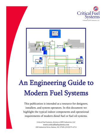
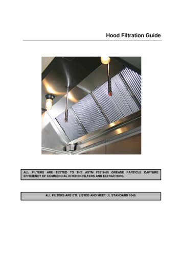
Fuel FiltersFor Fuel Pre lter Description and Operation, click here.For Fuel Pre lter Removal, click here.For Fuel Pre lter Inspection, click here.For Fuel Pre lter Installation, click here.For Coalescer/Final Filter Description and Operation, click here.For Coalescer/Final Filter Removal, click here.For Coalescer/Final Filter Inspection, click here.For Coalescer/Final Filter Installation, click here.Fuel Pre lter Description and OperationThe Fuel Inlet carries un ltered fuel passes into Fuel Pre lter. The Pre lter Check Ball is pushed off its seat by fuelentering the Pre lter, as a result of which the ow through the Pre lter Element from inside to outside is allowed.The pre- ltered fuel ows through the Fuel Outlet to the Low Pressure Pump leaving the larger dirt particles inthe pre lter element. Pre lter Check Ball prevents fuel from draining out of the Pre lter Housing when the engineis stopped. A drain to the Fuel Accumulator is opened for the fuel to ow out of the Fuel Pre lter Housing whenremoving the Pre lter Element.Figure 1. Fuel Pre lter -ResetEnlargeClick mouse and drag to view zoomed image.1/8
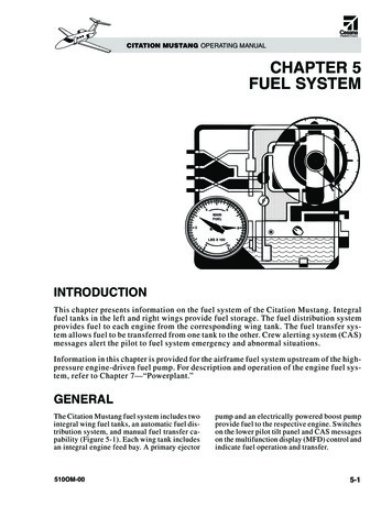
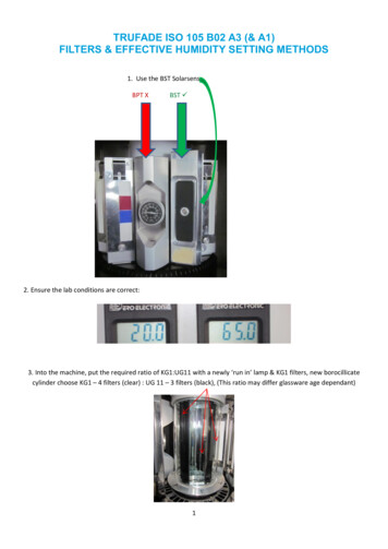
Fuel Pre lter RemovalWarning:During the operation of engine, do not attempt to remove any engine component, so that injury can beavoided.PERSONAL INJURYPut on protective gloves, or allow engine to cool, prior to the removal of any components, to prevent injuriesfrom hot surfaces.1. Turn the engine OFF.2. Engage the Parking Brake.3. Block the wheels.4. Carry out any other safety steps as applicable.CAUTION:ELECTRICAL SHOCK: To avoid injury from electrical shock, use care when connecting battery cables.The magnetic switch studs are at battery voltage.5. Disconnect the batteries.6. Open the hood.7. Unscrew the pre lter cap with a 36 mm Socket.8. Remove the Cap and Pre lter from the Fuel Filter Housing by pulling it straight up.9. Place the Filter on a solid surface and apply pressure on Pre lter Cap at an angle to remove the Pre lterfrom the Pre lter Cap.Figure 2. Removing Pre lter -ResetEnlargeClick mouse and drag to view zoomed image.2/8
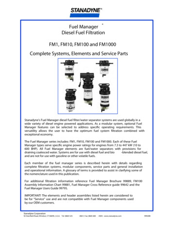
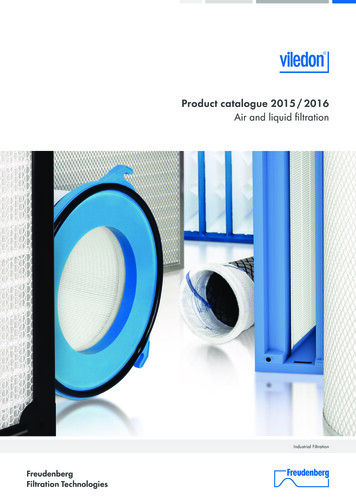
10. Check visually for any signs of fuel contamination in the Fuel Pre lter. Carry out the appropriatetroubleshooting if fuel is detected to be contaminated. Dispose of the Pre lter.11. Check for any large debris inside the Housing and clean it as required.12. Dispose of the O-ring of the Pre lter Cap.Fuel Pre lter Inspection1. Check visually for damage on the threads on the owing components:Fuel Pre lter CapFuel Filter ModuleReplace if needed.2. Check visually for rips or tears at the Filtering Element if not replacing the Fuel Pre lter. Replace the FuelPre lter if there is any damage at the Filtering Element.3. Check visually for damage or deformation on the Lower Filter O-rings if not replacing the Fuel Pre lter.Replace the Fuel Pre lter if the Lower Filter O-rings are damaged.Fuel Pre lter InstallationNote: Prior to priming, replace all the other lters, if performing a lter service.1. Mount a new Pre lter Cap O-ring onto the Pre lter Cap.2. Install new Pre lter into the Pre lter Cap by snapping it in.3. Apply the Pre lter O-rings and the Pre lter Cap O-ring with a thin coat of petroleum-based lithium grease.Figure 3. Pre lter O-Rings -ResetEnlargeClick mouse and drag to view zoomed image.3/8
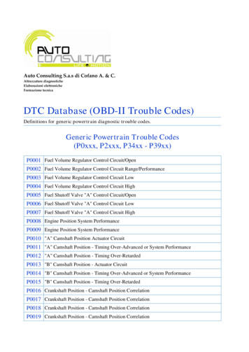
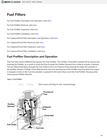
4. Install the Pre lter into the Fuel Filter Module.5. Rotate the cap in counterclockwise direction till a click sound can be heard. Then rotate it in clockwisedirection to tighten by hand.6. Tighten the Pre lter Cap to 41-44 lb-ft (55-60 Nm).CAUTION:ELECTRICAL SHOCK: To avoid injury from electrical shock, use care when connecting battery cables.The magnetic switch studs are at battery voltage.7. Connect the batteries.8. Prime the Fuel System after replacing all required Filters.For DD13, see Priming the Fuel System-KM63 GEN2-Two-Filter System.For DD15, see Priming the Fuel System-KM63 GEN2-Two-Filter System.For DD16, see Priming the Fuel System-KM63 GEN2-Two-Filter System.9. Shut the hood.Coalescer/Final Filter Description and OperationCoalescer/Final Filter element comprises several layers and performs the following:Separates water contained in the fuelFilters small dirt particlesFuel ows from outside to inside in Coalescer/Final Filter Element. The Coalescer/Final Filter Element is speciallyconstructed, such that small water droplets either remain within it or bind themselves to water droplets that areretained already. In addition to this, the construction also accounts for ltering small dirt particles out.The fuel ow rate is necessary to be reduced for to allow water droplets to sink down into the water bowl. Thehousing design solely aids in achieving this. The shape housing then increase the fuel ow rate again.A Water-In-Fuel (WIF) Sensor detects water level in the Water Bowl. Motor Control Module (MCM) will send anappropriate message to illuminate an indicator lamp if it detects excessive water in the water bowl.The water will be required to be drained with the aid of Mechanical Drain Valve for driver. Ventilation Bore allowsany air in the Filter Cavity to be removed in order to guarantee full use of Coalescer/Final Filter Element.Mechanical Drain Valve to the Fuel Transfer Bore/Fuel Accumulator is opened during Coalescer/Final Filter elementremoval so that fuel ows out of the Water Separator Housing.Coalescer/Final Filter element lters out the smallest dirt particles at a very high separation rate. An openinglocated close to the top of the Standpipe lets the cleaned fuel through to the High Pressure Fuel Pump. Uncleanfuel or water does not reach the High Pressure Fuel Pump because of the high position of the opening.Figure 4. Coalescer/Final Filter -ResetEnlargeClick mouse and drag to view zoomed image.4/8
Coalescer/Final Filter RemovalWarning:During the operation of engine, do not attempt to remove any engine component, so that injury can beavoided.PERSONAL INJURYPut on protective gloves, or allow engine to cool, prior to the removal of any components, to prevent injuriesfrom hot surfaces.Note: Never tilt the water coalescer/ nal lter when removing it from the housing, as it can possiblydamage the water coalescer/ nal lter or stand pipe.1. Turn the engine OFF.2. Engage the Parking Brake.3. Block the wheels.4. Carry out any other safety steps as applicable.CAUTION:ELECTRICAL SHOCK: To avoid injury from electrical shock, use care when connecting battery cables.The magnetic switch studs are at battery voltage.5. Disconnect the batteries.6. Open the hood.7. Unscrew the Water Coalescer/Final Filter Cap with a 36 mm Socket.8. Leave the fuel to drain back by pulling the Cap and Water Coalescer/Final Filter straight up.9. Place the Filter on a solid surface with the Drain Back Plug positioned at 12 O'clock and apply pressure onthe Water Coalescer/Final Filter Cap at an angle to remove the Water Coalescer/Final Filter from the WaterCoalescer/Final Filter cap.Figure 5. Removing Water Coalescer/Final Filter -ResetEnlargeClick mouse and drag to view zoomed image.5/8
10. Check visually for any signs of fuel contamination at the Coalescer/Final Filter. Carry out the appropriatetroubleshooting if there is fuel contamination. Dispose of the Water Coalescer/Final Filter if theCoalescer/Final Filter will be replaced.11. Check for large debris within the Housing and clean the Housing as required.12. Dispose of Water Coalescer/Final Filter Cap O-ring.Coalescer/Final Filter Inspection1. Check visually the threads on the Fuel Filter Module and Coalescer/Final Filter Cap. If damaged threads aredetected, replace as needed.2. Check visually for rips or tears at the ltering Element, if not replacing the Coalescer/Final Filter. Replace theCoalescer/Final Filter if the Filtering Element is damaged.3. Check visually for deformation or damage on the lower lter O-rings, if not replacing the Coalescer/FinalFilter. Replace the Coalescer/Final Filter if the Lower Filter O-rings are damaged.Coalescer/Final Filter InstallationNote: Prior to priming the fuel system, replace all the other fuel lters, if performing the fuel lterservice.1. Mount a new O-ring onto the Water Coalescer/Final Filter Cap and snap it into the Water Coalescer/FinalFilter Cap.2. Coat the Water Coalescer/Final Filter Cap with a light coat of petroleum-based lithium grease.3. Coat the upper and lower seals on the Water Coalescer/Final Filter with a thick layer of petroleum-basedlithium grease.Figure 6. Water Coalescer/Final Filter Assembly -ResetEnlargeClick mouse and drag to view zoomed image.6/8
Figure 7. Lubricating Upper and Lower Seals -ResetEnlargeClick mouse and drag to view zoomed image.4. Install the Water Coalescer/Final Filter into the Fuel Filter Module.Note: Drain back port is at 10 o'clock position on the fuel lter module when viewed from top.5. Position the Drain Back Plug in line with the Drain Back Port by rotating the Water Coalescer/Final FilterCap in counterclockwise direction.6. Seat the Drain Back Plug into the Drain Back Port by gently pressing on the top of the WaterCoalescer/Final Filter Cap.7. Rotate the Filter Cap in clockwise direction to hand-tighten it.8. Tighten the Water Coalescer/Final Filter Cap to 41-44 lb-ft (55-60 Nm).CAUTION:ELECTRICAL SHOCK: To avoid injury from electrical shock, use care when connecting battery cables.The magnetic switch studs are at battery voltage.9. Connect the batteries.10. Prime the Fuel System after replacing all required Filters.For DD13, see Priming the Fuel System-KM63 GEN2-Two-Filter System.For DD15, see Priming the Fuel System-KM63 GEN2-Two-Filter System.For DD16, see Priming the Fuel System-KM63 GEN2-Two-Filter System.11. Shut the hood.7/8
8.Prime the Fuel System after replacing all required Filters. For DD13, see Priming the Fuel System-KM63 GEN2-Two-Filter System. For DD15, see Priming the Fuel System-KM63 GEN2-Two-Filter System. For DD16, see Priming the Fuel System-KM63 GEN2-Two-Filter System. 9.Shut the hood. Coalescer/Final Filter Description and Operation