Transcription
ReprintFull-field digital mammography with grid-lessacquisition and software-based scatter correction:Investigation of dose saving and image qualityAndreas Fieselmann, Daniel Fischer, Ghani Hilal, Frank Dennerlein, Thomas Mertelmeier, and Detlev Uhlenbrock
Page 2 April 2013Full-field digital mammography withgrid-less acquisition and software-basedscatter correction: Investigation of dosesaving and image quality*Andreas Fieselmann1, Daniel Fischer1, Ghani Hilal2, Frank Dennerlein1, Thomas Mertelmeier1, and Detlev Uhlenbrock313Siemens AG, Healthcare Sector, Erlangen, Germany; 2 University of Düsseldorf, Düsseldorf, Germany;University of Bochum, Bochum, Germany and St.-Josefs-Hospital, Dortmund, GermanyAbstract1. IntroductionAnti-scatter grids used in full-field digital mammographynot only attenuate scattered radiation but also attenuateprimary radiation. Dose saving could be achieved if theeffect of scattered radiation is compensated with a software-based scatter correction not attenuating the primaryradiation. In this work, we have carried out phantom studiesin order to investigate dose saving and image quality ofgrid-less acquisition in combination with software-basedscatter correction. The results show that similar image quality (contrast-to-noise ratio and contrast-detail visibility)can be obtained with this alternative acquisition and postprocessing scheme at reduced dose. The relative dose reduction is breast-thickness-dependent and is 20% for typicalbreast thicknesses. We have carried out a clinical studywith 75 patients that showed non-inferior image qualityat reduced dose with our novel approach compared to thestandard method.X-ray mammography requires a high image quality for thedetection of subtle features indicating malignant tissue.Scattering is a physical process that degrades image quality.1Scattered radiation generates a smoothly varying, noisybackground that is added to the image. The varying background signal decreases relative image contrast. Furthermore, the additive noise reduces the contrast-to-noiseratio (CNR).Keywords: digital mammography, scattered radiation,scatter correction, anti-scatter grid, dose reduction, featureanalysis study.In mammography reduction of scattered radiation istraditionally achieved by using hardware approaches. Antiscatter grids are most frequently used. Other approachesinclude using slot or multislit scanning2, 3 or applying anair gap.4 Besides reducing the amount of scattered radiation, anti-scatter grids also attenuate primary radiation.The primary radiation is the radiation that passes throughthe breast without being absorbed or scattered by thebreast tissue. The attenuating effect of an anti-scatter gridis usually expressed in terms of the Bucky factor Bf 1/Ttwith Tt being the total transmission of the grid. Bf 2 is atypical value.5 To compensate for the (unintended) attenuation of primary radiation of the grid a higher entrancedose is necessary.Since asymptomatic women undergo mammographyscreening, dose is of highest importance in breast imaging.In order to reduce entrance dose – and therefore also theorgan dose – several studies have been carried out thatinvestigate grid-less acquisition for digital mammography.6-12* Fieselmann, A., Fischer, D., Hilal, G., Dennerlein, F., Mertelmeier, T.,and Uhlenbrock, D., “Full-field digital mammography with grid-lessacquisition and software-based scatter correction: investigation ofdose saving and image quality,” In: Proceedings of SPIE MedicalImaging 2013: Physics of Medical Imaging, Lake Buena Vista, FL,USA, vol. 8668, pp. 86685Y, (2013), doi:10.1117/12.2007490
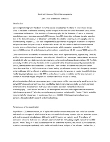
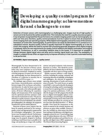
Page 3 April 2013 subtract scatter field–segment breastcomputed scatter fielddatabase withscattering kernelsinput imagescatter field imageoutput imageFigure 1. Simplified illustration of the software-based scatter correction.2. Software-based scatter correctionIn a subset of these studies software-based scatter correction (SBSC) has been included as an image post-processingstep.9-12 With SBSC it is possible to mitigate the effect ofscattered radiation by software-based methods instead ofhardware methods. SBSC can particularly reduce the varying background signal caused by the scattered radiation.The additive noise due to scatter is of stochastic nature andit can be compensated by the relative increase in primaryradiation.These studies suggest a potential for dose reduction withuncompromised image quality for grid-less mammography.E. g., Gennaro et al.8 did not use SBSC and state that dosesaving by 15–25% was possible for PMMA equivalent breaststhinner than 40 mm. Tromans et al.12 used SBSC and statethat dose can be reduced by 37–49% for their phantomstested (e. g. CIRS BR3D phantom). Although these studiesshow very promising results no clinical study in this fieldhas been carried out yet. In our work, we present our novelapproach for grid-less acquisition and SBSC. We evaluatedour approach using phantom-based measurements and aclinical study with 75 patients.The measured radiation without grid consists of primaryand scattered radiation. The scattered radiation can bemodeled by a low-frequency and a high-frequency component. The low-frequency component generates a smoothlyvarying additive offset to the intensity values in the image.The high-frequency component is basically additive noise.The purpose of the SBSC is to estimate the low-frequencycomponent and subtract it from the measured image. Notethat the decrease of the CNR due to the high-frequencycomponent of the scattered radiation can be compensatedby the increased transmission of primary radiation for thecase of the grid-less acquisition.We apply a scatter correction algorithm* for full fielddigital mammography (FFDM) that estimates the scatterfield depending on the object using 2D scatter kernels andconvolution.13, 14 Scatter kernels representing local scatterfractions were generated by Monte Carlo simulations basedon object properties and the geometry and acquisitionsparameters (e. g., anode/filter combination, tube voltage)of a commercially available FFDM system (MAMMOMATInspiration; Siemens AG, Healthcare Sector, Erlangen,Germany). Figure 1 shows a simplified illustration of thisalgorithm.The total computation time for the scatter correction isshort (of the order of seconds) and the usual workflowduring screening mammography is not affected due towaiting times.*T he technology is not available in all countries. Due to regulatoryreasons its future availability cannot be guaranteed.
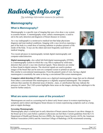
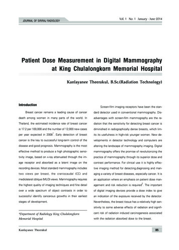
Page 4 April 201335ROI1 cm2dose reduction factor [%]detectorAL 0.2 mm216 cmmeasured valuesfit3025201510PMMA20304050607080chest wall sideequivalent compressed breast thickness [mm](a) experimental set-up(b) results90Figure 2. Experimental set-up and results of the CNR measurement.3. Phantom StudyWe have carried out phantom experiments in order toaddress the following two questions:1. What relative dose reduction can be achieved withgrid-less acquisition and SBSC compared to a standardacquisition (with grid) while providing the same CNR inthe image?2. When using grid-less acquisition and SBSC at this reduceddose level, how does the contrast-detail visibility15 of theseimages compare to those images acquired in standard mode(with grid)?3.1 Material and methods:contrast-to-noise ratio measurementsInvestigating CNR is relevant for grid-less acquisition due tothe high-frequency noise component of scatter. We measured CNR for different polymethyl methacrylate (PMMA)plate thicknesses according to the EUREF guidelines.15PMMA plates of thickness between 20 and 70 mm in stepsof 10 mm were placed on the detector of a MAMMOMATInspiration as illustrated in Figure 2a. An aluminium (AL)foil of 0.2 mm thickness was placed on top of the PMMAplates.First an image with grid was acquired in standard automatic exposure control mode. Then the grid was removedand a set of images was acquired using the same beamquality (filter/anode combination, tube voltage) but withvarying exposures from 100% to about 50% of the exposure of the first image. Note that the exposure could bevaried in certain discrete steps only. In each image (bothacquisition modes, all PMMA thicknesses) two regionsof interest (ROIs), one being inside and one being outsideof the position of the AL-foil (Figure 2a), were used tocompute the CNR corresponding to that image.15For each PMMA thickness we determined the exposurewhich yields the same CNR with a grid-less acquisition compared to the acquisition with grid. A fit of the squared CNRvalues versus exposure was used for determining preciseexposure values. Thus, for each PMMA thickness two exposure values exist which provide the same CNR for acquisitions with and without grid, respectively. From the twoexposure values a PMMA-thickness-dependent dose reduction factor for grid-less acquisition was computed. This procedure was performed separately without and with SBSC.The results for a specific PMMA thickness were convertedto an equivalent compressed breast thickness using theconversion table presented in Dance et al.16
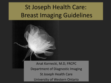
Page 5 April 201320 mm phantom thickness, 21 mm equivalent CBT2.83w/ gridw/o grid SBSC (31% dose reduction)2.00disc thickness [ 060.050.040.030.060.08 0.100.13 0.16 0.20 0.25 0.310.40 0.50 0.63 0.80 1.00 1.251.60 2.00disc diameter [mm]30 mm phantom thickness, 32 mm equivalent CBT2.83w/ gridw/o grid SBSC (35% dose reduction)2.00disc thickness [ 060.050.040.03We used the feature plate of the CDMAM 3.4 phantom(Artinis Medical Systems B.V., AS Zetten, the Netherlands)in order to measure the contrast-detail curves15 of imagesacquired with and without grid. For the latter case theimages were acquired using the same beam quality but ata reduced dose according to the results from the previousCNR measurements. PMMA blocks were used to generatedifferent phantom thicknesses (20–70 mm in steps of10 mm) that simulate different equivalent compressedbreast thicknesses. See again Dance et al.16 for the conversion factors. The feature plate itself is equivalent to 10 mmPMMA. The evaluation of the CDMAM phantom images wasperformed with the automatic scoring software CDCOM.17Eight images were acquired for every phantom thickness,processed by CDCOM and contrast-detail curves weredetermined.3.3 Results0.060.08 0.100.13 0.16 0.20 0.25 0.310.40 0.50 0.63 0.80 1.00 1.251.60 2.00disc diameter [mm]60 mm phantom thickness, 75 mm equivalent CBT2.83w/ gridw/o grid SBSC (11% dose reduction)2.001.42disc thickness [ μm]3.2 Material and methods:contrast-detail measurements1.00Figure 2b shows the dose reduction factors (DRF) as afunction of equivalent compressed breast thickness (CBT)with an additional linear fit ( r 0.99, p 0.001). TheDRF fit has a slope of –0.34%/mm. The results for the DRFwithout SBSC are similar (the slope of the fit is –0.37%/mm).Representative contrast-detail curves for three differentphantom thicknesses are shown in Figure 3.0.713.4 0.040.030.060.08 0.100.13 0.16 0.20 0.25 0.310.40 0.50 0.63 0.80 1.00 1.251.60 2.00disc diameter [mm]Figure 3. Log-log plots of contrast-detail curves of theacquisitions with grid and without grid and SBSC atreduced dose level for different equivalent compressedbreast thicknesses (CBT).The measured DRF are monotonously decreasing and canbe very well modeled by a linear function. The dependence of the DRF on the breast thickness will be explainednext. With increasing breast thickness the scatter fraction18and the amount of additive noise due to scatter increases.A certain amount of the additional primary radiation –due to removal of the grid – is needed to compensate forthis noise. Thus less additional primary radiation is available to compensate for the lower dose. In order to providethe same CNR the dose cannot be reduced by the samefactor for thicker breasts compared to thinner breasts. Thecontrast-detail curves of the acquisitions with and withoutgrid are generally very similar indicating that similar imagequality can be obtained using the two different acquisitionapproaches. The higher relative dose reduction for 30 mmPMMA thickness (35%) compared to 20 mm PMMA thickness (31%) is due to the limited, discrete choice of valueswhen selecting the exposure parameters for the manualacquisition without grid.
Page 6 April 20133.0AGD [mGy]2.5w/gridw/o grid SBSC2.01.5SDp-valueoverall comparison of image quality0.070.31 10-14diagnostic certainty: mass0.120.30 10-13diagnostic certainty: microcalcification0.080.42 10-070.180.28 10-070.000.16 10-240.090.29 10-100.010.22 10-17diagnostic certainty: architecturaldistortionvisibility of tissue near the edge of thebreastvisibility of structures in the pectoralmuscle1.00.50meancategoryvisibility of noise25-3435-4445-5455-6465-7475-8485-94breast thickness [mm]Figure 4. Average glandular dose in the clinical study(error bars represent 1 standard deviation).4. Clinical StudyWe have carried out a clinical feature-analysis study inorder to investigate the grid-less acquisition and SBSC withreduced dose under realistic clinical conditions.4.1 Material and methods75 female patients were enrolled in this clinical study whohad been recalled for further diagnostic mammogramsafter screening. The clinical study has been approved bythe ethics committee. Informed written consent to participate in this study was obtained from all patients.For each patient, two exposures were made during thesame compression phase. The breast side and the laterality(CC or MLO) were randomly chosen. The first exposure wasmade in standard automatic mode with grid. The secondexposure was made without grid and with reduced dose.The dose was reduced by lowering the tube current-timeproduct according to the factors determined in the phantomexperiment (Figure 2b) and keeping the other acquisitionparameters constant. The images acquired without gridwere processed with the SBSC described in Section 2 beforeprocessing them using standard mammographic imageprocessing algorithms.19The image pairs were evaluated by five radiologists eachhaving more than five years of experience in interpretingmammograms. In a blinded side-by-side reading of theimage pairs, the radiologists had to compare the imageson a 7-point scale ( 3, 2, . . . , 3) according to the following seven categories:1. overall image quality2. diagnostic certainty: mass3. diagnostic certainty: microcalcification4. diagnostic certainty: architectural distortion5. visibility of tissue near the edge of the breast6. visibility of structures in the pectoral muscle7. visibility of noiseTable 1. Results for the reading study comparing imagepairs on the 7-point scale (SD: standard deviation).Positive mean values indicate better impression with thegrid-less technique with SBSC.After the blinded reading the ratings were transformedonto a 7-point scale where positive values indicate preference of the grid-less technique with SBSC. Based onbiostatistical considerations and previous (unpublished)studies, non-inferiority of the grid-less technique is assumedfor a rating –0.3 points on the 7-point scale.4.2 ResultsThe study population is characterized as follows. The meanage of the women was 56.5 5.5 years (50 to 72 years).The mean compressed breast thickness was 57.5 14.7 mm(28 to 87 mm). The distribution of mammographic findingsin the study population was: masses (57%), microcalcifications (41%), architectural distortions (20%). Note thatmultiple findings per patient were possible. The breastdensity in the study population was rated as: ACR 1 (4%),ACR 2 (53%), ACR 3 (33%), ACR 4 (10%).Figure 4 shows the distribution of the average glandulardose (AGD) in the study population. The absolute AGDreduction averaged over all patients was 0.26 0.06 mGy.The relative AGD reduction ranges from 12% (breast thickness 85–94 mm) to 32% (breast thickness 25–34 mm).The results from the reading study are shown in Table 1.In this table, positive mean values indicate a preferencefor the grid-less acquisition with SBSC. All mean values areclose to zero. The p-values corresponding to a one-sidedt-test (a 0.025) with threshold set to –0.3 are shown aswell. Using this t-test, statistical significant non-inferiorityof the grid-less technique in combination with SBSC hasbeen shown (p 0.001).One pair of images from the clinical study is presentedin Figure 5 (39 mm breast thickness, 27% relative dosereduction).
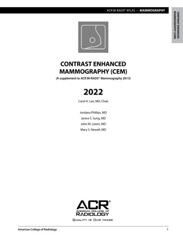
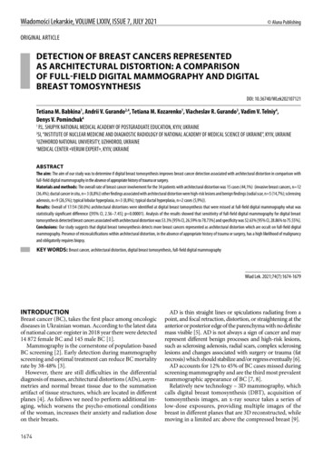
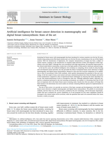
Page 7 April 2013w/ gridw/o grid SBSCw/ gridw/o grid SBSC(27% less dose)Figure 5. Example images from the clinical study with a magnification of a region of interest containingmicrocalcifications (marked with arrows). The image without grid and SBSC was acquired with 27% less dose(0.76 mGy instead of 1.04 mGy) compared to the image acquired in standard mode with grid.4.3 DiscussionReferencesIn the clinical study, the relative, breast-thickness-dependentdose reduction obtained with grid-less mammography withSBSC is very similar to that obtained in the phantom study.Differences may be due to the limited, discrete choice ofexposure values that can be selected in manual exposuremode. Interestingly, the average absolute reduction of AGD(0.26 mGy) is similar across breast thickness ranges. A doseincrease is necessary for thicker breasts which – in combination with the decrease of relative dose reduction forthicker breast – leads to this similar absolute value.[1] B ushberg, J. T., Seibert, J. A., Leidholdt, E. M., and Boone, J. M., [The Essential Physicsof Medical Imaging], Lippincott Williams & Wilkins, Philadelphia, PA, 3 rd ed. (2012).[2] S hen, S. Z., Bloomquist, A. K., Mawdsley, G. E., Yaffe, M. J., and Elbakri, I.,“Effect of scatter and an antiscatter grid on the performance of a slot-scanning digitalmammography system,” Medical Physics 33(4), 1108–1115 (2006).[3] Å slund, M., Cederström, B., Lundquist, M., and Danielsson, M., “Scatter rejectionin multislit digital mammography,” Medical Physics 33(4), 933–940 (2006).[4] K rol, A., Bassano, D. A., Chamberlain, C. C., and Prasad, S. C., “Scatter reductionin mammography with air gap,” Medical Physics 23(7), 1263–1270 (1996).[5] S alvagnini, E., Bosmans, H., Struelens, L., and Marshall, N. W., “Quantification ofscattered radiation in projection mammography: Four practical methods compared,”Medical Physics 39(6), 3167–3180 (2012).[6] V eldkamp, W. J. H., Thijssen, M. A. O., and Karssemeijer, N., “The value of scatterremoval by a grid in full field digital mammography,” Medical Physics 30(7),1712–1718 (2003).[7] D iekmann, F., Diekmann, S., Berzeg, S., Bick, U., Fischer, T., and Hamm, B.,“Dose reduction through gridless technique in digital full-field mammography,”Fortschritte Röntgenstrahlen 175, 769–774 (2003). (article in German).[8] G ennaro, G., Katz, L., Souchay, H., Klausz, R., Alberelli, C., and di Maggio, C.,“Grid removal and impact on population dose in full-field digital mammography,”Medical Physics 34(2), 547–555 (2007).[9] B aydush, A. H. and Floyd, C. E., “Improved image quality in digital mammographywith image processing,” Medical Physics 27(7), 1503–1508 (2000).[10] N ykänen, K. and Siltanen, S., “X-ray scattering in full-field digital mammography,”Medical Physics 30(7), 1864–1873 (2003).[11] X ia, J., Floyd, C., Lo, J., and Harrawood, B., “Improved signal to noise in full-field digitalmammography by replacing the anti-scatter grid with nonlinear image processing,”in [Proceedings of the Radiological Society of North-America (RSNA) 2004], (2004).(unpublished).[12] Tromans, C. E., Cocker, M., and Brady, S. M., “Digital scatter removel for mammography and tomosynthesis image aquisition,” in [Proceedings of the 11 th InternationalWorkshop on Digital Mammography (IWDM) 2012], 7361, 260–267 (2012).[13] R ührnschopf, E.-P. and Klingenbeck, K., “A general framework and review of scattercorrection methods in x-ray cone-beam computerized tomography. Part 1: Scattercompensation approaches,” Medical Physics 38(7), 4296–4311 (2011).[14] R ührnschopf, E.-P. and Klingenbeck, K., “A general framework and review ofscatter correction methods in cone beam CT. Part 2: Scatter estimation approaches,”Medical Physics 38(9), 5186–5199 (2011).[15] P erry, N., Broeders, M., de Wolf, C., Törnberg, S., Holland, R., von Karsa, L.,and Puthaar, E., eds., [European Guidelines for Quality Assurance in Breast CancerScreening and Diagnosis], Office for Official Publications of the EuropeanCommunities, Luxembourg, 4 th ed. (2006).[16] D ance, D. R., Young, K. C., and van Engen, R. E., “Further factors for the estimation ofmean glandular dose using the United Kingdom, European and IAEA breast dosimetryprotocols,” Physics in Medicine and Biology 54(14), 4361–4372 (2009).[17] Young, K. C., Alsager, A., Oduko, J. M., Bosmans, H., Verbrugge, B., Geertse, T., andvan Engen, R., “Evaluation of software for reading images of the CDMAM test object toassess digital mammography systems,” in [Proceedings SPIE Medical Imaging 2008:Physics of Medical Imaging], 6913, 69131C (2008).[18] M ertelmeier, T. and Bernhardt, P., “Scatter in digital mammography: antiscatter gridversus slot-scanning,” in [Proceedings SPIE Medical Imaging 2005: Physics of MedicalImaging], 5745, 299–306 (2005).[19] Z anca, F., Jacobs, J., Ongeval, C. V., Claus, F., Celis, V., Geniets, C., Provost, V.,Pauwels, H., Marchal, G., and Bosmans, H., “Evaluation of clinical image processingalgorithms used in digital mammography,” Medical Physics 36(3), 765–775 (2009).It is important to assess the image quality at the reduceddose with grid-less mammography and SBSC. The ratingsby the radiologists have mean values close to zero. This isactually an indicator for the same image quality. The mainresults of the clinical study is that statistically significantnon-inferiority of the grid-less technique with SBSC can beshown.5. SummaryPatient dose in X-ray mammography is a highly relevanttopic. In our work, we presented an investigation regardingthe dose saving potential of grid-less FFDM in combinationwith SBSC. Dose can be reduced with grid-less mammography due to a relatively higher amount of primary radiation reaching the detector. We have carried out phantomstudies to investigate the dose saving potential and imagequality. In order to test our technique under realisticconditions we conducted a clinical study which showednon-inferiority of this approach compared to the standardapproach. The relative dose reduction is breast thicknessdependent and varies between 12% for the thicker breasts(85–94 mm) and 32% for the thinner breasts (25–34 mm)in the study.
Not for distribution in the USA.On account of certain regional limitationsof sales rights and service availability,we cannot guarantee that all productsincluded in this brochure are availablethrough the Siemens sales organizationworldwide. Availability and packagingmay vary by country and are subjectto change without prior notice. Some/Allof the features and products describedherein may not be available in the UnitedStates.The information in this documentcontains general technical descriptionsof specifications and options as well asstandard and optional features whichdo not always have to be present inindividual cases.Siemens reserves the right to modify thedesign, packaging, specifications, andoptions described herein without priornotice. Please contact your local Siemenssales representative for the most currentinformation.Note: Any technical data contained inthis document may vary within definedtolerances. Original images alwayslose a certain amount of detail whenreproduced.Please find fitting accessories:siemens.com/medical-accessoriesSiemens Healthcare HeadquartersSiemens Healthcare GmbHHenkestr. 12791052 ErlangenGermanyPhone: 49 9131 84-0siemens.com/healthcareOrder No. A91XP-30005-23E1-7600 Printed in Germany CC 3807 05161. Siemens Healthcare GmbH, 2016siemens.com/healthcare
Keywords: digital mammography, scattered radiation, scatter correction, anti-scatter grid, dose reduction, feature analysis study. 1. Introduction X-ray mammography requires a high image quality for the detection of subtle features indicating malignant tissue. Scattering is a physical process that degrades image quality.1