Transcription
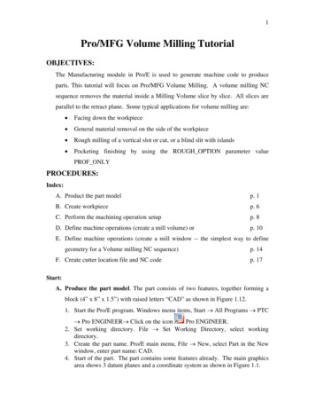
MiTMSuper Fast Thread Milling SystemInserts Toolholders
Vardex Ordering Code System MiTM InsertsMiTMR1252I31.004ISO5TM6VBX71- Product Line2 - Insert Style3 - Type of Insert4 - Pitch5 - Standard6 - System7 - Carbide GradeR- MiTM line19, 24, 25, 40, 41I - InternalE - ExternalEI-External InternalNC- Plug0.5-6.0 mm32-4 tpiISO- ISO MetricUN-American UNW- BSW, BSPNPT-NPTNPTF-NPTFBSPT-BSPTTMVBXVTX MiTM HoldersR1TM21- Product LineR - MiTM lineBR - MiTM with Antivibration SystemC3254175-266S7282 - Holder Type3 - Cooling4 - Shank Dia. [mm]5 - Cutting Dia. [mm]TM - Standard HolderTMN - Conical HolderC- Coolant Channel12, 20, 25, 3210 - 366 - Tool Overhang [mm]7 - Insert Style8 - No. of Flutes19 - 80A - 19M - 24S - 25L - 40B - 411-5 MiTM Shell MillR1TM2C3-D364-165-25S6571- Product Line2 - Holder Type3 - Cooling4 - Cutting Dia. [mm]5 - Drive Hole Dia. [mm]R - MiTM lineTM - Standard HolderTMN - Conical HolderC- Coolant Channel36 - 5816, 22, 276 - Insert Style7 - No. of Flutes25S40L41B5-8232
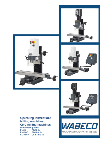
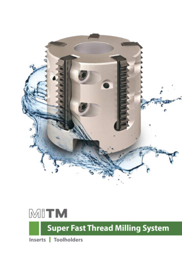
The VARDEX Multi-flute Indexable Thread Milling (MiTM)system for fast machining, reduces cycle times whenmachining threads with long inserts. Nickel coating forall MiTM toolholders provides better anti-rust protection.StandardConicalMiTM 19 (A)For SmallBoresStandardNo. of Flutes (Z) 1Cutting Dia. (D2) 10.2Tool Overhang (L1) 19.0MiTMNo. of Flutes (Z) 1Cutting Dia. (D2) 10.0-11.75Tool Overhang (L1) 20.0-25.2ConicalMiTM 24 (M)For MediumBoresNo. of Flutes (Z) 1-2Cutting Dia. (D2) 13.6-16Tool Overhang (L1) 26-36No. of Flutes (Z) 1Cutting Dia. (D2) 13.9Tool Overhang (L1) 26StandardConicalNo. of Flutes (Z) 2-5Cutting Dia. (D2) 17-30Tool Overhang (L1) 26-80No. of Flutes (Z) 2-4Cutting Dia. (D2) 17-28Tool Overhang (L1) 26-43Shell MillMiTM 25 (S)Shell MillConicalFor StandardApplicationsNo. of Flutes (Z) 5-8Cutting Dia. (D2) 36-52Tool Overhang (L1) max.200StandardShell MillNo. of Flutes (Z) 3-4Cutting Dia. (D2) 22-30Tool Overhang (L1) 43-80No. of Flutes (Z) 6-8Cutting Dia. (D2) 44-52Tool Overhang (L1) max.200StandardShell MillNo. of Flutes (Z) 1-5Cutting Dia. (D2) 24.5-36Tool Overhang (L1) 43-65No. of Flutes (Z) 5-6Cutting Dia. (D2) 48-58Tool Overhang (L1) max.200MiTM 40 (L)No. of Flutes (Z) 5Cutting Dia. (D2) 36Tool Overhang (L1) max.200Shell MillConicalFor LongThreadsNo. of Flutes (Z) 6Cutting Dia. (D2) 45Tool Overhang (L1) max.200MiTM 41 (B)For LargePitches233
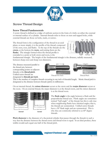
ISO MetricExternal / Internal1/4PInternal60 LLLMiTM 19262 (DIN 13)s: 6g/6HLeLeLeMiTM 24MiTM 25LeLe1/8P ExternalDefined by: R262 (DIN 13)Tolerance class: 6g/6HLLMiTM 40MiTM 41MiTMStandard MiTMLPitchmmmm1924254041Ordering CodeExternalCutting 124.0122.5R24I2.50ISOTM.125.0101.0R25E1.00ISOTM. R25I1.00ISOTM.224.0241.25R25E1.25ISOTM. R25I1.25ISOTM.223.75191.5R25E1.50ISOTM. R25I1.50ISOTM.224.0162.0R25E2.00ISOTM. R25I2.00ISOTM.224.0122.5R25E2.50ISOTM. R25I2.50ISOTM.225.0103.0*R25E3.00ISOTM. 00ISOTM. R41I3.00ISOTM.239.0133.5R41E3.50ISOTM. R41I3.50ISOTM.238.5114.0R41E4.00ISOTM. M.240.5985.0R41E5.00ISOTM. R41I5.00ISOTM.240.05.5R41E5.50ISOTM. R41I5.50ISOTM.238.576.0R41E6.00ISOTM. R41I6.00ISOTM.236.06* 3.0 ISO inserts do not fit into toolholder RTMC2517.For external insert 3.0 ISO use for CNC program (D2 0.5mm).MiTM inserts 25, 40 and 41 are offered with 2 cutting edges. In case of chip flow difficulty,inserts with a single cutting edge can be ordered by request. Example: B)RTMC.S(B)RTMC.LRTMC.B
External / Internal1/4PInternal60 LeLeL1/8P ExternalLeLLMiTM 19MiTM 24MiTM 25Defined by: ANSI B1.1:74Tolerance class: 2A/2BStandard MiTMLPitchmmtpi192425Ordering CodeExternalCutting * 8 UN & 9 UN inserts do not fit into toolholder RTMC2517.For external insert 8 UN use for CNC program (D2 0.5mm).MiTM inserts 25, 40 and 41 are offered with 2 cutting edges. In case of chip flow difficulty,inserts with a single cutting edge can be ordered by request. Example: R25I20UNTM(S).235MiTMANSI B1.1:74ass: 2A/2BAmerican UN - UNC, UNF, UNEF, UNS
American UN - UNC, UNF, UNEF, UNS (con’t)External / Internal1/4PNSI B1.1:74s: 2A/2BInternal60 LeLe1/8P ExternalLLMiTM 40MiTM 41MiTMDefined by: ANSI B1.1:74Tolerance class: 2A/2BStandard MiTMLPitchmmtpi4041Ordering CodeExternalCutting I4UNTM.238.106MiTM inserts 25, 40 and 41 are offered with 2 cutting edges. In case of chip flow difficulty,inserts with a single cutting edge can be ordered by request. Example: R25I20UNTM(S).236TeethLe(B)RTMC.LRTMC.B
External / InternalR 0.137PLeLeLeInternalL55 R 0.137PLLMiTM 19MiTM 25MiTM 24LeLeExternalDefined by: B.S.84:1956, DIN 259,DIN ISO228/1:1982Tolerance class: Medium Class ALLMiTM 41MiTM 40Standard MiTMLPitchmmtpiExternal 11924254041Ordering CodeCutting 239.91116R41I6WTM.238.109ToolholderMiTM956, DIN 259,1:1982um Class AWhitworth for BSF, BSP (G)RTMC.ARTMC.M(B)RTMC.S(B)RTMC.LRTMC.BMiTM inserts 25, 40 and 41 are offered with 2 cutting edges. In case of chip flow difficulty,inserts with a single cutting edge can be ordered by request. Example: R25EI16WTM(S).237
NPTMiTM Inser ts - 25mmMiTM Inser ts - 25mmExternal** / InternalExternal** / InternalExternal / InternalInternalIntern30 30 1 47'1 47'1 47'L90 LLMiTM19R25NC Plug InsertR25NC Plug Insert1:1968ard NPTLeLeLeExternExternalDefined by: USAS B2.1:1968Tolerance class: Standard NPTLe1 47'Le1 47’MiTM 25MiTM 241 47'LLMiTM 40MiTM 41Standard MiTMMiTML1:1968ard NPTPitchOrdering CodemmtpiExternal MNC.SRTMNC-D36-16-25S5RTMNC-D45-22-40L6RTMC.BMiTM Inser ts - 25mmMiTM Inser ts - 25mmExternal** / InternalExternal** / InternalExternal / Internal1 47'1 47'1 47'LMiTM 25MiTM 24R25NC Plug InsertLeExternalExternLLMiTM 19R25NC Plug Insert1 47’LeLeLeInternalIntern30 30 90 Cutting EdgeLe1 47'1 47'Defined by: ANSI B1.20.3-1976Tolerance class: Standard NPTFLLMiTM 40MiTM 41Standard MiTMLPitchOrdering CodemmtpiExternal ting B
MiTM Inser ts - 25mmBSPTExternal** / InternalExternal / InternalR0.137P1 47'InternalMiTM Inserts - 25mm27.5 27.5 1 47'External** / Internal90 R25NC Plug InsertLLMiTM 19MiTM 24Le1 47' R0.137PExternalLe1 47'1 47'Defined by: B.S. 21:1985Tolerance class: Standard BSPTLLMiTM 25R25NC Plug InsertMiTM 40Standard MiTMLPitchOrdering CodemmtpiExternal I19BSPT-TM.124.0618RTMNC .123.091011R40EI11BSPT-TM.139.25172540Cutting g InsertLOrdering CodeTeethmmExternal InternalZt24R24NCRTMC.M25R25NC(B)RTMC.SRTMNC.SNo BAll TypesFill unused toolholder pockets with plug inserts (R.NC).This assures balance and prevents instability and chips from packing into empty pockets.239MiTM1985ndard BSPTLeLe
Standard Toolholders (MiTM 19)D2DL1D1LCoolant-Thru is recommended, especially when D2 0.7 x nominal thread diameterMiTMRTMC - for Standard ThreadsInsert StyleOrdering CodemmSpare PartsDimensions mmNo. of 5A173.525.2128.711.75119LocationScrew x2Torx ScrewdriverSLD3IP6(M3x0.5)KIP6Use the included VardexTorx screwdriver only.Recommendedmax. torque 1.2 NxMStandard Thread Application by ToolholderToolholderMin. Thread rse)ISO(fine)UNCM11x0.75; M11.5x1;M12x1.75 M11x0.5;M12x1.25; M12x1.51M14x2.0; M12.5x0.5; M13x0.75; M13x1;M16x2.0 M13.5x1.25; M14x1.5; M14x1.759 2 -13 16-12UN/UNF/UNEF/UNS7119BSFBSP(G) 16-32UN; 7 16-28UNEF; 7 16-27UNS; 1 2 -24UNS; 2 -20UNF; 1 2 -18UNS; 1 2 -16UN; 1 2 -14UNS1 2 -161 4 -19 2 -32UN; 9 16-28UNS; 9 16-27UNS; 9 16-24UNEF; 16-20UN; 9 16-18UNF; 9 16-16UN; 9 16-14UNS;5 8 -141 4 -142 Step Clamping SystemSide with screw location holes.240Always mount all inserts withscrew location holes face up.To mount insert correctly,push the insert toward thepocket walls.FastenFirst1FastenSecond2
Conical Toolholders (MiTM 19)D2D1 47'L1D1LCoolant-Thru is recommended, especially when D2 0.7 x nominal thread diameterRTMNC - for Conical ThreadsOrdering Codemm19Dimensions mmLRTMNC1210-19A1L166.5D1912MiTMInsert StyleSpare PartsNo. of FlutesD1D2810.6ZLocationScrew x2Torx Screwdriver1SLD3IP6(M3x0.5)KIP6Use the included VardexTorx screwdriver only.Recommendedmax. torque 1.2 NxMConical Thread Application by ToolholderToolholderD2(mm)RTMNC1210-19A1*10.6NPT13 4 -18* 8 -18NPTF13 4 -18* 8 -18BSPT13 4 -19* 8 -19Using MiTM 19 tools the maximum thread length is 10.5mm.2 Step Clamping SystemSide with screw location holes.Always mount all inserts withscrew location holes face up.FastenFirst1FastenSecond2To mount insert correctly,push the insert toward thepocket walls.241
Standard Toolholders (MiTM 24)D2DD1L1D1LCoolant-Thru is recommended, especially when D2 0.7 x nominal thread diameterMiTMRTMC - for Standard ThreadsInsert StyleOrdering Codemm24Spare PartsDimensions mmNo. of C2016-36M191362012.6161LocationScrew x2Torx ScrewdriverSLD4IP8(M4x0.7)KIP8Use the included VardexTorx screwdriver only.Recommendedmax. torque 1.2 NxMStandard Thread Application by ToolholderToolholderMin. Thread M16x2M14.5x0.5; M15x0.75; M15x1;M15x1.25; M16x1.5; M16x1.75RTMC2015-30M115.1M18x2.5M16x0.5; M17x0.75; M17x1;M17x1.25; M17x1.5;M18x1.75; M18x23RTMC2016-28M216M17x0.5; M17x0.75; M18x1;M20x2.5 M18x1.25; M18x1.5;M18x1.75; M19x23 4 -10RTMC2016-36M116M17x0.5; M17x0.75; M18x1;M20x2.5 M18x1.25; M18x1.5;M18x1.75; M19x23 4 -10Side with identificationmarks.242Always mount all insertswith identification marksface up.- 4 -10UN/UNF/UNEF/UNSBSF 16-12UN; 5 8 -14UNS; 5 8 -16UN; 5 8 -18UNF; 8 -20UN; 5 8 -24UNEF; 5 8 -28UN; 5 8 -32UNBSP(G)11113 16-14; 4 -123513 4 -12UN; 3 4 -14UNS; 11 16-16UN; 11 16-20UN; 16-24UNEF; 11 16-28UN; 11 16-32UN3 4 -121 2 -14 4 -12UN; 3 4 -14UNS; 3 4 -16UN; 3 4 -18UNS; 4 -20UNEF; 11 16-24UNEF; 11 16-28UN; 11 16-32UN3 4 -121 2 -14 4 -12UN; 3 4 -14UNS; 3 4 -16UN; 3 4 -18UNS; 4 -20UNEF; 11 16-24UNEF; 11 16-28UN; 11 16-32UN3 4 -121 2 -14113333 8 -19; 2 -14Side without identificationmarks.To mount insert correctly,push the insert toward thepocket walls.
Conical Toolholders (MiTM 24)D2D1 47'L1D1LCoolant-Thru is recommended, especially when D2 0.7 x nominal thread diameterRTMC - for Conical ThreadsOrdering CodeDimensions mmmm24LRTMNC2014-26M1L181D2620MiTMInsert StyleSpare PartsNo. of FlutesD1D211.513.9ZLocationScrew x2Torx Screwdriver1SLD4IP8(M4x0.7)KIP8Use the included VardexTorx screwdriver only.Recommendedmax. torque 1.2 NxMConical Thread Application by ToolholderToolholderThread Dia.D2(mm)RTMNC2014-26M1On Conical inserts, theidentification mark mustface up.13.9NPTNPTF 8 -1833Side without identificationmarks. 8 -18BSPT3 8 -19To mount insert correctly,push the insert toward thepocket walls.243
StandardToolholders(MiTMStandardToolholders(For 25)Inser ts 25mm)D2DD1L1D1LCoolant-Thru is recommended, especially when D2 0.7 x nominal thread diameterMiTMRTMC - for Standard ThreadsInsert StyleOrdering Codemm25Spare PartsDimensions mmLL1DNo. of cationScrew x2SLD4IP8(M4x0.7)Torx ScrewdriverKIP8Use the included VardexTorx screwdriver only.Recommendedmax. torque 1.2 NxMStandard Thread Application by 4Min.Thread Dia.D2(mm)ISO(coarse)ISO(fine)17M20x2.5M19x1; M19x1.5;M20x219M22x2.5M24x3M21x1; M21x1.5;M22x220.5M24x3M22x1; M23x1.5;M23x2; M23.5x2.522M27x3M24x1; M24x1.5;M25x2; M25x2.5M32x1; M32x1.5;M33x2; M33x2.5; M34x330Side with identification marksSide with identification marks244-Side without identificationSidewithout identification marksmarks.UNC 8 -9;1-87UN/UNF/UNEF/UNSBSF7 8 -10UNS; 13 16-12UN; 7 8 -14UNF; 4 -16UNF; 3 4 -18UNS; 3 4 -20UNEF737 8 -20UNEF; 7 8 -18UNS; 7 8 -16UN; 8 -14UNF; 7 8 -12UN; 7 8 -10UNS77BSP(G) 8 -11; 7 8 -12; 8 -14; 7 8 -161 -16; 7 8 -14; -12; 15 16-115 2 -1478151615 16-9UN; 1-10UNS; 15 16-12UN;1-14UNS; 15 16-16UN; 7 8 -18UNS; 7 8 -20UNEF1-11; 1-12;1-14; 1-165-111 16-8UN; 1-9UN; 1-10UNS; 1-12UNF;1-14UNS; 1-16UN; 1-18UN; 15 16-20UNEF1-11; 1-12;1-14; 1-163-13 8 -8UN; 13 8 -9UN; 13 8 -10UN; 15 16-12UN;13 8 -11; 13 8 -12;13 8 -14UNS; 15 16-16UN; 15 16-18UNEF; 15 16-20UN 13 8 -14; 13 8 -161-8Always mount all inserts withAlways mountall insertsidentificationmarkson theon the same side!same side. 8 -14 8 -14 4 -141-11To mountinsertTo mountinsert rdthepocketwalls.walls.toward the pocket
ConicalToolholders(MiTMConicalToolholders(For 25)Inser ts 25mm)D1D2D1 47'L1LCoolant-Thru is recommended, especially when D2 0.7 x nominal thread diameterRTMNC - for Conical ThreadsOrdering CodeDimensions mmmmRTMNC2517-26S225MiTMInsert StyleSpare PartsNo. of 822.23RTMNC2528-43S410343252528.44LocationScrew x2Torx ScrewdriverSLD4IP8(M4x0.7)KIP8Use the included VardexTorx screwdriver only.Recommendedmax. torque 1.2 NxMConical Thread Application by ToolholderToolholderThread Dia.D2(mm)NPTRTMNC2517-26S217.21 2 -14; 3 4 -14; 1-11.5; 11 4 -11.5;11 2 -11.5; 2-11.51RTMNC2522-43S322.23 4 -14; 1-11.5; 11 4 -11.5;11 2 -11.5; 2-11.53 4 -14; 1-11.5; 11 4 -11.5;11 2 -11.5; 2-11.53RTMNC2528-43S428.41-11.5; 11 4 -11.5;11 2 -11.5; 2-11.51-11.5; 11 4 -11.5;11 2 -11.5; 2-11.51-11; 11 4 -11; 11 2 -11; 2-11;21 2 -11; 3-11; 4-11; 5-11; 6-11On Conical inserts, theidentification mark mustface up.Side without identificationmarks.NPTF 2 -14; 3 4 -14; 1-11.5; 11 4 -11.5;11 2 -11.5; 2-11.5BSPT1 2 -14; 3 4 -14 4 -14; 1-11; 11 4 -11; 11 2 -11; 2-11;21 2 -11; 3-11; 4-11; 5-11; 6-11To mount insert correctly,push the insert towardthe pocket walls.245
Shell Mill (MiTM 25)D1 DaCombi Shell Mill Adaptor is preferableD2d(H7) D1DaAdaptor not includedHCoolant-Thru is recommended, especially when D2 0.7 x nominal thread diameterConical and Standard Shell MillsMiTMInsertStyleOrdering CodemmStandardConical*25Spare PartsNo. ofFlutesDimensions D36-16-25S53235.9*1633.55Location Screw x2Torx ScrewdriverHolder ScrewM8x1.25x35SLD4IP8(M4x0.7)KIP8Use the includedVardex Torx screwdriver only.Recommendedmax. torque 1.2 NxMM10x1.50x35M12x1.75x30M8x1.25x35For inserts 8NPT and 8NPTF use for CNC program 36.4mm.Standard Thread Applications by ToolholderToolholderMin. Thread Dia.D2(mm)StandardISO 8x1; M39x1.5;M39x2; M40x319 16-12UN; 15 8 -14UNS; 19 16-16UN;11 2 -18UNEF; 11 2 -20UN13 4 -1613 4 -1211 4 -11RTMC-D44-22-25S644M48x1; M48x1.5;M48x2; M48x317 8 -12UN; 113 16-16UN; 113 16-20UN;115 16-8UN; 17 8 -10UNS; 17 8 -14UNS2-162-1211 2 -11RTMC-D52-27-25S852M55x1; M55x1.5;M55x2; M56x321 4 -8UN; 21 4 -10UN; 21 4 -12UN;21 4 -14UN; 21 4 -16UN; 21 4 -18UN; 21 4 -20UN21 4 -1621 4 -122-11Conical Thread Applications by ToolholderToolholderThread Dia.D2(mm)Conical*RTMNC-D36-16-25S535.9*NPTNPTF11 4 -11.5; 11 2 -11.5; 2-11.521 2 -8 (and up)11 4 -11.5; 11 2 -11.5; 2-11.521 2 -8; 3-8BSPT11 2 -6x11For inserts 8NPT and 8NPTF use for CNC program 36.4mm.Side with identificationmarks.246Side withoutidentification marks.Always mount all insertson the same side!To mount insert correctly,push the insert towardthe pocket walls.
Standard(MiTMStandardToolholdersToolholders(For 40)Inser ts 40mm)D2D1DL1D1LCoolant-Thru is recommended, especially when D2 0.7 x nominal thread diameterRTMC - for Standard ThreadsOrdering Codemm40No. ofFlutesDimensions 142803226303MiTMInsertStyleSpare PartsLocation ScrewClamping Screw x2Torx ScrewdriverSCD4IP8(M4x0.7)KIP8Use the includedVardex Torx screwdriver only.Recommendedmax. torque 1.2 NxMSLD4IP8A(M4x0.7)Standard Thread Application by ToolholderToolholderMin. Thread Dia.D2ISO(mm) 22-43L322M27x3M24x1; M24x1.5M25x2; M25x2.5-111 16-8UN; 1-9UN; 1-10UNS; 1-12UNF;1-14UNS; 1-16UN; 1-18UN; 15 16-20UNEF1-11; 1-12;1-14; 1-16;3 4 -14RTMC2522-65L322M27x3M24x1; M24x1.5M25x2; M25x2.5-111 16-8UN; 1-9UN; 1-10UNS; 1-12UNF1-14UNS; 1-16UN; 1-18UN; 15 16-20UNEF1-11; 1-12;1-14; 1-16;3 4 -14RTMC3230-55L430-M32x1; M32x1.5M33x2; M33x2.5; M34x3-13 8 -8UN; 13 8 -9UN; 13 8 -10UN; 15 16-12UN;13 8 -14UNS; 15 16-16UN; 15 16-18UNEF; 15 16-20UN13 8 -11; 13 8 -12;13 8 -14; 13 8 -161-11BRTMC3230-80L330-M32x1; M32x1.5M33x2; M33x2.5; M34x3-13 8 -8UN; 13 8 -9UN; 13 8 -10UN; 15 16-12UN;13 8 -14UNS; 15 16-16UN; 15 16-18UNEF; 15 16-20UN13 8 -11; 13 8 -12;13 8 -14; 13 8 -161-112 Step Clamping SystemLocation 1ScrewClamping 2Screw x2Side with identificationmarks.Side withoutidentification marks.Always mount all insertson the same side!247
Shell Mill (MiTM 40)D1 DaCombi Shell Mill Adaptor is preferabled(H7) D1D2DaAdaptor not includedHCoolant-Thru is recommended, especially when D2 0.7 x nominal thread diameterConical and Standard Shell MillsMiTMInsertStyleOrdering Code40ConicalNo. ofFlutesDimensions mmmmStandardSpare ScrewSLD4IP8A(M4x0.7)ClampingScrew x2SCD4IP8(M4x0.7)Torx ScrewdriverHolderScrewM10x1.5x40KIP8Use the included VardexTorx screwdriver only. M12x1.75x40Recommendedmax. torque 1.2 NxM M10x1.5x40Standard Thread Application by ToolholderToolholderMin. Thread Dia.D2(mm)ISO (fine)UN/UNF/UNEF/UNSRTMC-D44-22-40L644M48x1; M48x1.5;M48x2; M48x317 8 -12UN; 113 16-16UN; 113 16-20UN;115 16-8UN; 17 8 -10UNS; 17 8 -14UNSRTMC-D52-27-40L852M55x1; M55x1.5;M55x2; M56x321 4 -8UN; 21 4 -10UN; 21 4 -12UN;21 4 -14UN; 21 4 -16UN; 21 4 -18UN; 21 4 -20UNStandardBSWBSP(G)2-162-1211 2 -1121 4 -1621 4 -122-11Conical Thread Application by ToolholderToolholderConicalRTMNC-D45-22-40L6Min. Thread Dia.D2(mm)NPT452-11.5; 21 2 -8 (and up)NPTF2-11.5; 21 2 -8; 3-8BSPT2-6x112 Step Clamping SystemLocation 1ScrewClamping 2Screw x2Side withidentification marks.248Side withoutidentification marks.Always mount all insertson the same side!
Standard Toolholders (MiTM 41)D2D1DD1L1LCoolant-Thru is recommended, especially when D2 0.7 x nominal thread diameterRTMC - for Standard ThreadsOrdering Codemm41No. ofFlutesDimensions 3228.335.95RTMC3236-65B4128653228.335.94Location Screw x2SLD4IP8A(M4x0.7)Clamping ScrewTorx ScrewdriverSCD4IP8(M4x0.7)KIP8Use the includedVardex Torx screwdriver only.Recommendedmax. torque 1.2 NxMStandard Thread Application by ToolholderToolholderMin. Thread BSW/BSFNPTNPTFRTMC2521-45B121.2M27x3; M30x3.5;M33x3.5; M36x4; M30x3; M42x4M39x41-8, 11 8 -7; 11 4 -7; 11 16-8UN; 17 16-6UN 1-8BSW; 11 8 -7BSW13 8 -6; 11 2 -6--RTMC2524-43B224.5M30x3.5; M36x4 M28x3; M45x411 8 -7; 13 8 -6RTMC3230-43B330.0M36x4; M42x4.5RTMC3230-65B330.0M36x4; M42x4.5RTMC3236-43B535.9M42x4.5; M48x5; M40x3; M40x3.5; 13 4 -5; 2-4.5;M56x5.5; M64x6 M42x4; M70x621 2 -4RTMC3236-65B435.911 8 -8UN; 17 16-6UN13 8 -8BSF; 11 4 -7BSW--M34x3; M34x3.5; 31 8 -6M45x413 8 -8UN; 17 16-6UN13 8 -8BSF; 13 4 -7BSF;11 2 -6BSW--M34x3; M34x3.5; 31 8 -6M45x413 8 -8UN; 17 16-6UN13 8 -8BSF; 13 4 -7BSF;11 2 -6BSW--15 8 -8UN; 15 8 -6UN15 8 -8BSF; 13 4 -7BSF;17 8 -6BSF21 2 -821 2 -8M42x4.5; M48x5; M40x3; M40x3.5; 13 4-5; 2-4.5; 21 2 -4 15 8 -8UN; 15 8 -6UNM56x5.5; M64x6 M42x4; M70x615 8 -8BSF; 13 4 -7BSF;17 8 -6BSF21 2 -821 2 -8For external applications, inserts R41E. use for CNC program (D2 0.6mm).2 Step Clamping SystemLocation 1Screw x2Clamping 2ScrewSide with identificationmarks.Side withoutidentification marks.Always mount all insertson the same side!249MiTMInsertStyleSpare Parts
Shell Mill (MiTM 41)D1 DaCombi Shell Mill Adaptor is preferableD2Dad(H7) D1Adaptor not includedHCoolant-Thru is recommended, especially when D2 0.7 x nominal thread diameterStandard Shell MillMiTMInsertStyleSpare PartsOrdering CodemmNo. ofFlutesDimensions 27-41B65057.92750641LocationScrew erScrewTorx ScrewdriverKIP8M10x1.5x40Use the included VardexTorx screwdriver only.Recommendedmax. torque 1.2 NxM M12x1.75x40Standard Thread Application by ToolholderToolholder*Min. Thread 0x6;21 4 -4.5; 21 2 -421 8 -8UN;21 8 -6UN21 4 -8;21 4 -621 2 -821 2 -8RTMC-D58-27-41B657.9M68x6M64x4;M70x623 4 -421 2 -8UN;21 2 -6UN21 2 -8;23 4 -621 2 -821 2 -8For external applications, inserts R41E. use for CNC program (D2 0.6mm).2 Step Clamping SystemLocation 1Screw x2Clamping 2ScrewSide with identification marks.250Side without identificationmarks.Always mount all inserts onthe same side!
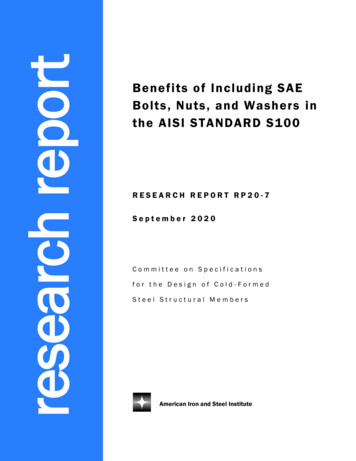
PSteelMKCast Iron(Excluding MiTM 19)(for MiTM 19)0.1-0.350.06-0.20.06-0.25100-210 90-1802 Unalloyed SteelMedium Carbon (C 0.25-0.55%)150100-180 90-1700.1-0.43High Carbon (C 0.55-0.85%)170100-170 90-1600.1-0.350.06-0.24Non Hardened18080-14090-1550.1-0.40.06-0.25Alloy Steel5 Low(alloying elements 5%) 070-14070-1500.1-0.30.06-0.27 High Alloy SteelAnnealed8 (alloying elements 5%) -1000.1-0.20.06-0.19Low Alloy (alloying elements 5%)200100-170 100-1700.1-0.30.06-0.2High Alloy (alloying elements 5%)22570-12070-1300.1-0.20.06-0.111 Stainless Steel12 FerriticNon Hardened200100-170 120-1800.1-0.30.06-0.2Hardened330100-170 120-1800.1-0.20.06-0.113 Stainless Steel14 AusteniticAustenitic18070-140 100-1400.1-0.30.06-0.2Super Austenitic20070-140 100-1400.1-0.20.06-0.115 Stainless Steel16 Cast FerriticNon Hardened20070-140 100-1400.1-0.30.06-0.2Hardened33070-140 100-1400.1-0.20.06-0.117 Stainless Steel18 Cast AusteniticAustenitic20070-120 100-1200.1-0.30.06-0.2Hardened33070-120 100-1200.1-0.20.06-0.128 Malleable29 Cast IronFerritic (short chips)13060-130 100-1200.05-0.160.03-0.1Pearlitic (long chips)23060-12080-1000.04-0.10.02-0.0630Low Tensile Strength18060-13080-1000.1-0.30.06-0.2High Tensile 0-12580-1000.1-0.30.06-0.23132Cast SteelGrey Cast IronNodular Sg Iron34 Aluminium Alloys35 Wrought3637Aluminium AlloysPearlitic26050-9060-900.1-0.20.06-0.1Non 5-0.50.09-0.3Cast75150-400-0.15-0.50.09-0.3Cast & t Si 13-22%13080-15039 Copper and40 Copper AlloysBrass90120-210 100-2000.15-0.50.09-0.3Bronze And Non Leaded Copper100120-210 100-2000.1-0.40.06-0.2519Annealed (iron based)20020-4520-400.1-0.20.06-0.120 High Temperature21 AlloysAged (iron based)28020-3020-300.04-0.10.02-0.06Annealed (nickel or cobalt based)25015-2015-200.04-0.10.02-0.06Aged (nickel or cobalt based)35010-1510-150.04-0.10.02-0.06Pure 99.5 Ti400Rm70-14070-1200.04-0.10.02-0.06α β 080.02-0.05HeatResistant 22Material 2324HVTX125Non-FerrousMetals 38 Aluminium AlloysSVBXFeed f [mm/tooth]Low Carbon (C 0.1-0.25%)33NMaterialVc [m/min]110StainlessSteelHardnessBrinellHBTitanium Alloys25HardenedMaterial 26Extra Hard SteelHardened & TemperedGradesGradeApplicationVBXTiCN coated carbide grade.Excellent grade for steels and general use.VTXTiAlN coated carbide grade.Ideal for Stainless Steels.Sample251MiTMMaterialGroupVargus No.Recommended Grades, Cutting Speeds Vc [m/min] and Feed f [mm/tooth]
The VARDEX Multi-flute Indexable Thread Milling (MiTM) system for fast machining, reduces cycle times when machining threads with long inserts. Nickel coating for all MiTM toolholders provides better anti-rust protection. No. of Flutes (Z) 1-2 Cutting Dia. (D2) 13.6-16 Tool Overhang (L1) 26-36 No. of Flutes (Z) 1 Cutting Dia. (D2) 13.9