Transcription
Part #71900Progressive Nitrous Controllerwww.edelbrock.comPlease study these instructions carefully before installing your new Progressive Nitrous Contoller. If you have any questions,please contact our Technical Hotline at : 1-800-416-8628 from 7 am - 5pm, Monday-Friday, Pacific Standard Time or e-mailus at Edelbrock@Edelbrock.com.Important Information -You must use Static Suppression Ignition Wires with this controller. The71900 Progressive Nitrous Controller contains high frequency digital electronics and will NOT function correctlywithout suppression wires.Warning - Do not mount the progressive controller anywhere near ignition components or any othersource of electronic noise.Notice - The controller must be grounded directly to the vehicle’s battery.Caution - Do not submerge the controller in liquid or directly wash the unit with liquid of any type!Warning - The programming switches are delicate electronic items and can be damaged by misuseand/or carelessness. If the controller is close to your nitrous bottle, be careful when installing the bottle.The weight of the bottle is enough to easily damage the switches. Switches that have been determinedto be damaged due to neglect will NOT be covered under warranty.Notice:It is the responsibility of the purchaser to follow all guidelines and safety procedures supplied with this product and anyother manufactures product used with this product. If is also the responsibility of the purchaser to determine compatibility ofthis device with the vehicle and other components.Edelbrock Corporation assumes no responsibility for damages resulting from accident, improper installation, misuse,abuse, improper operation, lack of reasonable care, or all previously stated reasons due to incompatibility with othermanufacturer’s products.Edelbrock Corporation assumes no responsibility or liability for damages incurred fron the use of products manufacturedor sold by Edelbrock Corporation on vehicles used for competition racing.Edelbrock Corporation neither recommends nor approves the use of products manufactured or sold by EdelbrockCorporation on vehicles which may be driven on public highways or roads, and assumes no responsibility for damages incurredfrom such use.It is the purchaser’s responsibility to check the state and local laws pertaining to the use of Nitrous Oxide for racingapplications. Edelbrock Corporation does not recommend nor condone the use of its products for illegal street racing.Installation of this Edelbrock product signifies that you have read this document and agree to the termsstated within.Caution:Follow all recommended safety guidelines from this and other manufacturer’s installation guides. Never install anydevice which pulsates nitrous solenoids without a safety solenoid installed. Static Suppression ignition wires must be used withthis unit! Mount the unit as far away from secondary ignition components (coil, ignition wires, etc.) as physically possible. 2009 Edelbrock CorporationPart #71900Page 1 of 17Brochure #63-0473Rev. 05/09 - AJ/mc
www.edelbrock.com71900 - Progressive Nitrous ControllerThe 71900 Progressive Nitrous Controller was designed using the latest digital technology available. Theresult is a controller which is extremely accurate and user-friendly. A simple and functional programming interfaceallows the user to set important nitrous parameters in a matter of seconds, all without the use of externalprogrammers or computers. An Options Menu has been included to enable the user to customize the controller for aparticular application. The Options Menu also contains a function that if selected will return the contoller to its originalfactory Pre-Programmed state.Features:Full Digital Circuitry:This design approach assures the best in performance and reliability.Digital technology provides extremely accurate control that cannot be achieved with analog systems.Easy to Read LED Display with Touch Switch Programming: This userinterface is very user-friendly and provides quick and accurate programming of the progressive nitrous controller.Integrated Battery Voltage Monitor:The battery voltage is displayed periodically onthe LED display.Non-Volatile Data Memory:No battery or power connection is needed to retain thecontrollers parameter settings. There is no need to re-program the controller after the battery is disconnected. Thereis NO internal battery, all data is stored in flash memory and will be retained for up to 10 years with no power appliedto the controller.Separate Nitrous and Fuel Solenoid Outputs: This design provides more outputcurrent capability. By using separate outputs, better control of the solenoid is achieved. The response of the nitroussystem is improved and much more accurate. The fuel output is programmed to function as though the fuel andnitrous solenoids were on the same output terminal. The Options Menu allows the user to program the fuel solenoidto operate in full progressive mode (i.e. - The fuel solenoid will pulse through the entire progression). 12 Volt Timer Output: A digital timer is provided that can be used to activate an ignition retardcontroller or a 2nd stage of nitrous. The output from activation terminal is on ( 12 volt applied). If the activationsignal is removed, the 12V timer will halt until the signal is re-applied. The 12v timer can be programmed from0.000 to 9.999 seconds. The Options Menu allows the user to configure the timer output behavior while the controlleris in the activated state. Optionally, the output can be configured to remain ON regardless of the activation input.NOTE - Setting the timer to 0.000 will disable the timer output. 2009 Edelbrock CorporationPart #71900Page 2 of 17Brochure #63-0473Rev. 05/09 - AJ/mc
www.edelbrock.comNitrous Delay Timer: A digital timer is provided that can be used to delay the start of the nitrous.This timer begins counting down when the activation terminal is on ( 12v applied). If the activation signal is removed,the delay timer will halt until the signal is re-applied. The delay timer can be programmed from 0.000 to 9.999seconds.Nitrous Starting Percentage: The user can program the amount of nitrous power that willbe applied after the nitrous delay timer has elapsed (Immediately if delay timer is set at 0.000). This parameter is setas a percentage and can range from 10% to 100%. If the starting power is more than the ending power, the nitrouspower will decrease with time.Final Nitrous Percentage:This setting allows the user to program how much nitrous poweris applied after the nitrous ramp has completed. This parameter is also set as a percentage and can range from 10%to 100%. By setting the final power percentage less than the starting percentage, the user can back off the nitrouspower.The Options Menu allows the user to select a single or dual ramp nitrous power ramp. When the dual rampmode is selected, there will be two final percents and two power ramp times.Nitrous Power Ramp Time:The power ramp time is used to determine the rate at whichthe nitrous power goes from the start percentage to the final percentage. The nitrous power ramp time can be setfrom .200 to 9.900 seconds.The Options Menu allows the user to select a single or dual ramp nitrous power ramp. When the dual rampmode is selected, there will be two final percents and two power ramp times.Intelligent Nitrous Progressive Timer: The progressive nitrous timer system will waitat its present state if the activation signal is removed. Nitrous progression will resume when the controller is reactivated. The entire nitrous and 12 volt timer system is automatically reset 20 seconds after activation.Optionally the nitrous timer system can be configured to RESET each time the activation signal is applied.This method would allow the nitrous power to be applied with each gear change or each time the throttle is lifted andre-applied. This feature is selected with the Options Menu.An added feature has been included to the timer system to help the user tune the nitrous power ramp. Whenthe timer system is activated ( 12v at the activation input) an internal timer is started which will record the time andpercent of the progressive cycle when the activation signal is removed. This data can be used to determine at whatpoint in the progressive cycle that the power ramp is too aggressive and the driver is lifting the throttle. 2009 Edelbrock CorporationPart #71900Page 3 of 17Brochure #63-0473Rev. 05/09 - AJ/mc
www.edelbrock.comTABLE OF CONTENTSPage #Programming 12 Volt Timer. . . . . . . . . . . . . . . . . . . . . . . . . . . . . . . . . . . . . . . . . . . . . . . . . . . . . . . . . . . . . . 5Nitrous Delay Timer . . . . . . . . . . . . . . . . . . . . . . . . . . . . . . . . . . . . . . . . . . . . . . . . . . . . . . . . . . 5Nitrous Starting Percentage . . . . . . . . . . . . . . . . . . . . . . . . . . . . . . . . . . . . . . . . . . . . . . . . . . . . 6Nitrous Ending Percentage. . . . . . . . . . . . . . . . . . . . . . . . . . . . . . . . . . . . . . . . . . . . . . . . . . . . . 6Nitrous Power Ramp Time . . . . . . . . . . . . . . . . . . . . . . . . . . . . . . . . . . . . . . . . . . . . . . . . . . . . . 7Example Nitrous Power Setting . . . . . . . . . . . . . . . . . . . . . . . . . . . . . . . . . . . . . . . . . . . . . . . . . 7Options Menu, ProgrammingViewing Run Data and Entering the Options Menu . . . . . . . . . . . . . . . . . . . . . . . . . . . . . . . . . . . 8Clearing Run Data (Reset for Next Run) . . . . . . . . . . . . . . . . . . . . . . . . . . . . . . . . . . . . . . . . . . . 8Resetting Controller to Factory Default. . . . . . . . . . . . . . . . . . . . . . . . . . . . . . . . . . . . . . . . . . . . 8Calibrating the Voltage Monitor . . . . . . . . . . . . . . . . . . . . . . . . . . . . . . . . . . . . . . . . . . . . . . . . . 8Setting the Dual Nitrous Power Ramp ON/OFF . . . . . . . . . . . . . . . . . . . . . . . . . . . . . . . . . . . . . . 9Setting Progressive Fuel Output ON/OFF . . . . . . . . . . . . . . . . . . . . . . . . . . . . . . . . . . . . . . . . . . 9Setting Activation Wait and Hold ON/OFF . . . . . . . . . . . . . . . . . . . . . . . . . . . . . . . . . . . . . . . . . . 9Setting 12V Timer Output Hold ON/OFF . . . . . . . . . . . . . . . . . . . . . . . . . . . . . . . . . . . . . . . . . 10Enabling Quick Data Access. . . . . . . . . . . . . . . . . . . . . . . . . . . . . . . . . . . . . . . . . . . . . . . . . . . 10Setting the RESET Timeout Period . . . . . . . . . . . . . . . . . . . . . . . . . . . . . . . . . . . . . . . . . . . . . . 10Exiting the Options Menu . . . . . . . . . . . . . . . . . . . . . . . . . . . . . . . . . . . . . . . . . . . . . . . . . . . . . 10Using the Dual Ramp FeatureHow the Dual Power Ramp Functions . . . . . . . . . . . . . . . . . . . . . . . . . . . . . . . . . . . . . . . . . . . 11Example Dual Ramp Nitrous Power Setting . . . . . . . . . . . . . . . . . . . . . . . . . . . . . . . . . . . . . . . 11InstallationItems Included with 71900 Controller . . . . . . . . . . . . . . . . . . . . . . . . . . . . . . . . . . . . . . . . . . . 12Items Needed that are NOT Supplied. . . . . . . . . . . . . . . . . . . . . . . . . . . . . . . . . . . . . . . . . . . . 12Cautions and Warnings . . . . . . . . . . . . . . . . . . . . . . . . . . . . . . . . . . . . . . . . . . . . . . . . . . . . . . 12Wiring Diagrams . . . . . . . . . . . . . . . . . . . . . . . . . . . . . . . . . . . . . . . . . . . . . . . . . . . . . . . . . . . 13Technical InformationElectrical Specifications. . . . . . . . . . . . . . . . . . . . . . . . . . . . . . . . . . . . . . . . . . . . . . . . . . . . . . 15Troubleshooting . . . . . . . . . . . . . . . . . . . . . . . . . . . . . . . . . . . . . . . . . . . . . . . . . . . . . . . . . . . . 15Service . . . . . . . . . . . . . . . . . . . . . . . . . . . . . . . . . . . . . . . . . . . . . . . . . . . . . . . . . . . . . . . . . . 16Warranty . . . . . . . . . . . . . . . . . . . . . . . . . . . . . . . . . . . . . . . . . . . . . . . . . . . . . . . . . . . . . . . . . 16 2009 Edelbrock CorporationPart #71900Page 4 of 17Brochure #63-0473Rev. 05/09 - AJ/mc
www.edelbrock.comProgramming the 12 Volt TimerPress and release the FUNCTION switch until the message “ 12V Timer Delay” appears on the display. Afterthe function message has scrolled across the display, the current 12 Volt Timer setting will appear on the display.To adjust the 12 volt timer value, press the desired digit button and the value of that digit will increment.The digit will roll over to 0 and begin counting up again if the user continues to release and press the digit button.To exit without saving the new value, press the FUNCTION switch and select another function.To save the new value, press and release the ENTER switch and the display will read “SAVED” and the newsetting is now saved.The range of the 12 volt timer is 0.000 to 9.999 seconds with a .001 second resolution.This setting will determine the amount of time in seconds before the 12 volt timer output becomes active(goes to 12V) after controller activation.NOTE - Setting timer to 0.000 will disable the 12V timer output. Set to 0.001 for quickactivation.Programming the Nitrous Delay TimerPress and release the FUNCTION switch until the message “Nitrous Delay Timer” appears on the display. Afterthe function message has scrolled across the display, the current Nitrous Delay Time setting will appear on the display.To adjust the nitrous delay timer value, press the desired digit button and the value of that digit will increment.The digit will roll over to 0 and begin counting up again if the user continues to release and press the digit button.To exit without saving the new value, press the FUNCTION switch and select another function.To save the new value, press and release the ENTER switch and the display will read “SAVED” and the newsetting is now saved.The range of the 12 volt timer is 0.000 to 9.999 seconds with a .001 second resolution.This setting will determine the amount of time in seconds before the nitrous becomes active (nitrous beginsat starting percentage) after controller activation. 2009 Edelbrock CorporationPart #71900Page 5 of 17Brochure #63-0473Rev. 05/09 - AJ/mc
www.edelbrock.comProgramming the Nitrous Starting PercentagePress and release the FUNCTION switch until the message “Starting Percentage” appears on the display.After the function message has scrolled across the display, the current nitrous starting percentage setting will appearon the display.To adjust the nitrous starting percentage value, press the desired digit button and the value of that digit willincrement. The digit will roll over to 0 and begin counting up again if the user continues to release and press the digitbutton. If the .1 digit button is pressed, the starting percentage will go to 100%, pressing again will set the startingpercentage back to 0%. The 1. digit is ignored for this function.To exit without saving the new value, press the FUNCTION switch and select another function.To save the new value, press and release the ENTER switch and the display will read “SAVED” and the newsetting is now saved.The range of nitrous starting percentage is 10% to 100% in 1% increments.This setting will determine the amount of nitrous to be applied after the nitrous delay timer has elapsed.Programming the Final Nitrous PercentageNOTE - If the dual ramp feature is enabled fron the options menu, there will be a “Final Percent #2” in themenu list. The programming method is the same as the “Final Percent #1”. Please refer to the section “OptionsMenu” and “Using the Dual Ramp Feature” for more information.Press and release the FUNCTION switch until the message “Final Percent #1” appears on the display. Afterthe function message has scrolled across the display, the current final nitrous percentage setting will appear on thedisplay.To adjust the final nitrous percentage value, press the desired digit button and the value of that digit willincrement. The digit will roll over to 0 and begin counting up again if the user continues to release and press the digitbutton. If the .1 digit button is pressed, the final percentage will go to 100%, pressing again will set the startingpercentage back to 0%. The 1. digit is ignored for this function.To exit without saving the new value, press the FUNCTION switch and select another function.To save the new value, press and release the ENTER switch and the display will read “SAVED” and the newsetting is now saved.The range of the nitrous final percentage is 10% to 100% in 1% increments.This setting will determine the amount of nitrous to be applied at the end of the nitrous power ramp time. 2009 Edelbrock CorporationPart #71900Page 6 of 17Brochure #63-0473Rev. 05/09 - AJ/mc
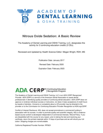
www.edelbrock.comProgramming the Nitrous Power Ramp TimeNOTE - If the dual ramp feature is enabled fron the options menu, there will be a “Nitrous Build Time #2” inthe menu list. The programming method is the same as the “Build Time #1”. Please refer to the section “OptionsMenu” and “Using the Dual Ramp Feature” for more information.Press and release the FUNCTION switch until the message “Nitrous Build Time #1” appears on the display.After the function message has scrolled across the display, the current nitrous power ramp time setting will appearon the display.To adjust the nitrous build time, press the desired digit button and the value of that digit will increment. Thedigit will roll over to 0 and begin counting up again if the user continues to release and press the digit button. The.01 and .001 digit is ignored for this function.To exit without saving the new value, press the FUNCTION switch and select another function.To save the new value, press and release the ENTER switch and the display will read “SAVED” and the newsetting is now saved.The range of the nitrous build time is .200 to 9.900 seconds in .1 second increments.This setting will determine the rate at which the nitrous power goes from starting to final percent. A shortpower ramp will make the nitrous power very aggressive and a long power ramp will make the nitrous power lessaggressive.Nitrous Delay Timer 1.000 secondsNitrous Starting Percentage 20%Final Nitrous Percentage 100%Nitrous Power Ramp Time 6.000 seconds 2009 Edelbrock CorporationPart #71900Page 7 of 17Brochure #63-0473Rev. 05/09 - AJ/mc
www.edelbrock.comViewing Run Data and Entering the Options MenuPress and release the FUNCTION switch until the message “Edelbrock Nitrous Systems - 71900” appears onthe display.Press and hold the ENTER switch, the display will show the time at which the activation input was turned OFFfor the previous progressive cycle. After 5 seconds, the display will show the nitrous percent at which the activationinput was tuned OFF for the previous progressive cycle. The controller will only save the first occurence afteractivation and only if the run data has been cleared (This procedure is outlined below).Continue to hold the ENTER switch until the display reads “RELEASE”. At this time, the controller has enteredthe Options menu. Please refer to the following instructions regarding the selections available here.NOTE - You may release the ENTER switch before entering the options menu and return to the Main Menu.Clearing Run Data(Reset for next run)Enter the Options Menu, “Clear Run Data” is the first option. Pressing ENTER will erase the current run data and thenreturn to the Main Menu. Pressing FUNCTION will select the next option available.Resetting Controller to Factory DefaultsEnter the Options Menu, press and release the FUNCTION switch until the message “Reset Factory DefaultSettings” appears on the display.Pressing ENTER will restore the controller to the factory default settings and then return to the Main Menu.Pressing FUNCTION will select the next option available.Calibrating the Voltage MonitorEnter the Options Menu, press and release the FUNCTION switch until the message “Calibrate VoltageMonitor” appears on the display.Using a volt meter, compare the volt reading on the display to the volt meter reading. Press and release theENTER switch to adjust the reading until it is correct.Refer to “Exiting the Options Menu” to return to the main menu.Pressing FUNCTION will select the next option available. 2009 Edelbrock CorporationPart #71900Page 8 of 17Brochure #63-0473Rev. 05/09 - AJ/mc
www.edelbrock.comSetting the Dual Nitrous Power Ramp ON/OFFEnter the Options Menu, press and release the FUNCTION switch until the message “Dual Ramp Nitrous”appears on the display.Press and release the ENTER switch to turn this feature ON or OFF. After pressing the ENTER switch, thedisplay will show the new state of the selected option. Refer to the “Exiting the Options Menu” to return to the mainmenu.If this option is ON (Factory Default is OFF) two more selections will appear on the Main Menu. Please referto the section “Using the Dual Ramp Feature” for more information.Setting Progressive Fuel Output ON/OFFEnter the Options Menu, press and release the FUNCTION switch until the message “Progressive Fuel SolenoidDriver” appears on the display.Press and release the ENTER switch to turn this feature ON or OFF. After pressing the ENTER switch, thedisplay will show the new state of the selected option. Refer to the “Exiting the Options Menu” to return to the mainmenu.When the option is ON, the fuel output will pulsate through the entire nitrous progressive cycle. If this optionis OFF (Default), then the fuel solenoid will pulsate for the first 5 pulses and then go to 100%.Setting Activation Wait and Hold ON/OFFEnter the Options Menu, press and release the FUNCTION switch until the message “Progressive Fuel SolenoidDriver” appears on the display.Press and release the ENTER switch to turn this feature ON or OFF. After pressing the ENTER switch, thedisplay will show the new state of the selected option. Refer to the “Exiting the Options Menu” to return to the mainmenu.When this option is ON (Factory Default) all timers, including the progressive timers, will halt if the activationsignal ( 12V) is removed and will resume when the signal is re-applied. If this option is OFF, all timers will be reseteach time the activation signal ( 12V) is removed (i.e. - Each time the activation signal is applied the controller startsat the beginning of the timing cycle). 2009 Edelbrock CorporationPart #71900Page 9 of 17Brochure #63-0473Rev. 05/09 - AJ/mc
www.edelbrock.comSetting 12V Timer Output Hold ON/OFFEnter the Options Menu, press and release the FUNCTION switch until the message " 12V Timer Output Hold"appears on the display.Press and release the ENTER switch to turn this feature ON or OFF. After pressing the ENTER switch, thedisplay will show the new state of the selected option. Refer to "Exiting the Options Menu" to return to the Main Menu.When this option is OFF (Factory Default) the 12V timer output will turn OFF each time the activation signalis removed.Enabling Quick Data AccessEnter the options menu, press and release the FUNCTION switch until the message "Quick Data Access"appears on the display.Press and release the ENTER switch to turn this feature ON or OFF. After pressing the ENTER switch, thedisplay will show the new state of the selected option. Refer to "Exiting the Options Menu" to return to the MainMenu.autoWhen this option is ON (Factory default is OFF), the data will appear before the text in the Main Menu. Thosefamiliar with the controller can access or check the current setup much more quickly.Setting the RESET Timeout PeriodEnter the Options Menu, press and release the FUNCTION switch until the message "Timeout in Seconds"appears on the display.Press and release the ENTER switch to increase the timeout period in 10 second increments. If the timeoutperiod is more than 180 seconds, the controller will default back to 20 seconds. Refer to "Exiting the Options Menu"to return to the Main Menu.NOTE - If the timeout period is 100 seconds or more the Run Data Time will be recorded in .01 second resolution.Exiting the Options MenuPress and release the FUNCTION switch until the message "Exit Options Menu" appears on the display.autoPress and release the ENTER switch to return to the Main Menu.Press and release the FUNCTION switch to return to the top of the options menu. 2009 Edelbrock CorporationPart #71900Page 10 of 17Brochure #63-0473Rev. 05/09 - AJ/mc
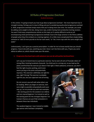
www.edelbrock.comHow the Dual Power Ramp FunctionsThe dual nitrous ramp feature enables the user to have more precise control over the nitrous power ramp.When the dual ramp feature is enabled, there are two more selections added to the Main Menu. These are "FinalPercent #1" and "Nitrous Build Time #2". Using these extra set points the user can build a power ramp that in nonlinear (i.e.- can be small power increase for 2 seconds and then ramp to full power very rapidly). Please view theexample outlined bellow for help in determining the proper setup for your application.Example Dual Ramp Nitrous Power SettingNitrous Delay Timer 1.000 secondsStarting Percent 20%Final Nitrous Percent #1 40%Nitrous Build Time #1 4.000 secondsFinal Nitrous Percent #2 100%Nitrous Build Time #2 2.000 seconds 2009 Edelbrock CorporationPart #71900Page 11 of 17Brochure #63-0473Rev. 05/09 - AJ/mc
www.edelbrock.comItems Included with the 71900 Controller1 - Wiring Harness2 - Installation & User ManualItems Needed that are NOT Supplied with Controller1 - Nitrous Kit2 - Safety Solenoid3 - Activation Switches as needed, if they were not included with the nitrous kit.4 - RPM Window Switch; required in EFI vehicles that have an over-rev fuel cut (See pg. 13)Cautions and Warnings1 - Always follow installation guidelines and safety precautions when installing any other relatedcomponents.2 - Remove battery connections when installing new components and/or wiring.3 - Always use proper circuit protection where required (Fuse).4 - Always test system operation after installation to insure proper operation.5 - Connect ground wire direct to battery negative terminal and then to controller.6 - EFI engines using an over-rev fuel cut must use an RPM window switch to avoid potential engine damage.IMPORTANT - Must use Static Suppression Ignition Wires. You cannot use any type of metal spiral core and/or metalcore ignition wires. Controller contains high frequency digital circuitry and cannot function properly with RFI or EMIinterference. 2009 Edelbrock CorporationPart #71900Page 12 of 17Brochure #63-0473Rev. 05/09 - AJ/mc
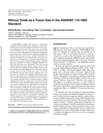
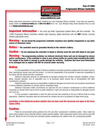
www.edelbrock.comTypical Progressive Controller Wiring DiagramAn optional RPM window switch may beconnected here. Any RPM switch with a groundcontrol output may be used.NOTE - Most factory fuel injection systems willcut the fuel during an over-rev condition. If thenitrous is NOT controlled by an RPM switch,engine damage may result.Progressive Controller with Transbrake Wiring ivation 12 Volts 12 Volt 12V Timer OutputGroundW.O.T.Switch878787AFuel SolenoidsNitrous Soelnoids86NitrousSolenoidGroundtoBattery 2009 Edelbrock CorporationPart #719003087A85FuelSolenoid 12 VoltsPage 13 of 1786Ground3085ArmingSwitchGround 12 VoltsBrochure #63-0473Rev. 05/09 - AJ/mc
2009 Edelbrock CorporationPart #71900Page 14 of Ground to Battery8586Trans oundTo Other Side ofToggle Switch onShock ControllerGroundGround67 12 Volt 12 Volt30To Power Side ofTogge Switch onShock witch5867 12 VoltGround3MSD Multi Step RetardNOTE: Refer to individual component manufacturer for specific connection informationCoil Coil IGNPointsM M-287A8730MSD 2 StepProgressiveController71900Activation 12 Volt 12 Timer OutputGroundFuel SolenoidNitrous SolenoidMSD 7AL-2 12 VoltTrans Brake Button 12 VoltNitrous Arming SwitchTo CrankTriggerProgressive Controller Wiring Diagram with Several OptionsBrochure #63-0473Rev. 05/09 - AJ/mc
www.edelbrock.comElectrical SpecificationsNormal Operating Voltage10.0 to 16.0 Volts, Negative GroundController will turn OFF at 6.2 Volts 12 Volt Timer Output1 AMP Maximum, 80mA sink to ground when timer output is OFF.Nitrous Solenoid Ground45 AMPs MaximumActivation Input.5mA at 12.0 VoltsWeightOverall HeightOverall WidthOverall Length.8 lb.1.125 in.4.000 in.4.700 in.Caution - DO NOT submerge controller in liquid or directly wash unit with liquid of any type!Preventing RF / EM Interference with Progressive ControllerTypical Progressive Controller RF / EM Interference SymptomIf your progressive controller’s active display flashes on and off or resets itself during operation causing the vehicle tosurge, it may be caused by electromagnetic interference generated by the engine’s ignition system or other vehiclecomponents.RFI / EMI Controller Backing PlateRF / EM interference can be reduced by using a 3/16” or thicker plate to cover the rear face of the controller. Plateand housing surfaces must be flat sanded to assure a tight fit; no sealant should be applied to surfaces. This backingplate can be fabricated with basic shop tools and is also available by contacting our technical support department.Controller MountingDo not mount the progressive controller anywhere near ignition components or any other source of electronic noise.If you have difficulty isolating the controller from RF / EM interference, it may help to mount the controller in the rearportion of the interior as far from the firewall, ignition components, and wiring harnesses as possible. Controllershould be mounted on flexible rubber mounts or Velcro to assure the housing is not in contact with the vehicle chassisor other common ground plane.Vehicle WiringEdelbrock recommends using a DVOM (digital vo
www.edelbrock.com Page 3 of 17 Nitrous Delay Timer: A digital timer is provided that can be used to delay the start of the nitrous. This timer begins counting down when the activation terminal is on ( 12v applied). If the activation signal is removed,