Transcription
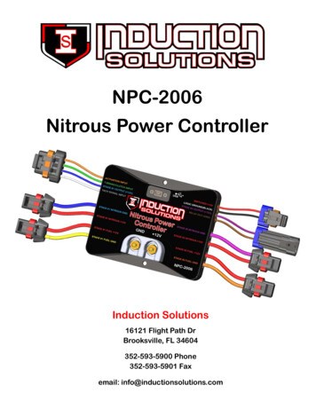
NPC-2006Nitrous Power ControllerInduction Solutions16121 Flight Path DrBrooksville, FL 34604352-593-5900 Phone352-593-5901 Faxemail: info@inductionsolutions.com
2What is Included with the NPC‐2006 kit.NPC‐2006 Nitrous Controller.Wiring Harness with sealed automo ve connectors.8ga heavy duty solenoid power supply wires.High Amperage Relay.Installa on hardware kit.USB flash drive with PC so ware and a pdf file of the user manual.User ManualImportant Informa on ‐ When using a conven onal style igni on coil (Not Coil on Plug) you must useSta c Suppression Igni on Wires with this Controller.Cau on ‐ Do NOT submerge Controller in liquid or directly wash unit with liquid of any type! (Do NOT spraywhen washing vehicle!)It is the responsibility of the purchaser to follow all guidelines and safety procedures supplied withthis product and any other manufactures product used with this product. It is also the responsibility of thepurchaser to determine compa bility of this device with the vehicle and other components.Induc on Solu ons assumes no responsibility for damages resul ng from accident, improper installa‐on, misuse, abuse, improper opera on, lack of reasonable care, or all previously stated reasons due to in‐compa bility with other manufacturer's products.Induc on Solu ons assumes no responsibility or liability for damages incurred from the use of prod‐ucts manufactured or sold by Induc on Solu ons on vehicles used for compe on racing. Induc on Solu onsneither recommends nor approves the use of products manufactured or sold by Induc on Solu ons on vehi‐cles which may be driven on public highways or roads, and assumes no responsibility for damages incurredfrom such use.WarrantyInduc on Solu ons warrants to the original purchaser that the controller shall be free from defects inparts and workmanship under normal use for 180 days from the date of purchase.Induc on Solu ons obliga on under this warranty is limited to the repair or replacement of any com‐ponent found to be defec ve when returned postpaid to Induc on Solu ons. The Controller must be re‐turned with evidence of place and date of purchase or warranty will be void. The warranty will not apply ifthe controller has been installed incorrectly, repaired, damaged, or tampered with by misuse, negligence oraccident.2
3ContentsSo ware Installa onSystem RequirementsInstalla on StepsPage 4Page 4Using the So wareGeneral OverviewFile MenuController MenuPreferences MenuData MenuHelp MenuPage 7Page 8Page 8Page 9Page 9Page 9Stage1 TabSetupNitrousFuelPage 10Page 11Page 13Stage2 TabSetupNitrousFuelPage 15Page 16Page 18Timer Stage1 TabPage 20Timer Stage2 TabPage 21Relay Output TabPage 22Configura on TabPage 23Data TabData SetupData ChartPage 24Page 24Controller Installa onWiring DiagramTransmission Brake/Clutch Input WiringRPM/Tachometer Input WiringStage1 12 Volt Timer Output WiringStage2 12 Volt Timer Output WiringRelay Ground Output WiringPage 25Page 26Page 26Page 27Page 27Page 27Controller Firmware UpdateUpdate Controller FirmwarePage 28Appendix A—Se ng up the controller for a runPage 30Appendix B—Typical procedure when making a runPage 31Appendix C—Retrieving data log a er a runPage 323
4System RequirementsOpera ng systemWindows XP Home or Professional with Service Pack 3 installed.Informa on—if the text is not forma ed or sized correctly with Windows XP opera ng system follow the instruc ons belowto adjust the display dots per inch (dpi) se ng.For Windows XP the screen dpi se ng must be set to default or 96 dpi.1—Open Display in Control Panel.2—On the Se ngs tab, click Advanced.3—On the General tab, in the DPI se ng list, click 96 dots per inch (dpi).4—Restart your computer when prompted.Windows Vista all versions.Windows 7 all versions.Windows 8.x all versions.Windows 10 all versions.So ware Installa on StepsThe Nitrous Power Controller so ware is located on the USB flash drive included with the NPC‐2006 kit. Plug the USB flashdrive into an available USB port on the computer.Important—the so ware must be located and started manually from the USB flash drive. The auto run feature is not imple‐mented to provide increased security. Please follow the steps below to locate the so ware installa on program.Please use one of the following methods to open Windows file explorer.1—Press the Windows logo key e together.2—click on the File Explorer icon in the task bar.3—click Start, point to All Programs, point to Accessories, and then click Windows Explorer.4
5Le click on the Induc on Solu ons Drive.Double click on NPC‐2006 Setup5
6Click on the “Next” bu on and follow the installa on wizard prompts as needed.Important—Please allow the installa on wizard to install the so ware in the default loca on when prompted.You may be prompted to allow installa on from an unknown publisher, click on “Yes” to con nue with installa on.Allow the installa on program to complete.On the Windows desktop you will find a “Nitrous Power Controller” icon.Double click to start the so ware.Note—When the so ware is installed a link to start the so ware will also be placed in the program start menu. The installa on pro‐gram also creates a link to un‐install the so ware. If you no longer wish to have it installed or you need to remove a previous versionbefore upda ng to a more current version you may select this link from the All Programs/Induc on Solu ons selec on.6
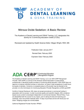
7General OverviewMenu barToolbar menuHover mouse cursor over icon forinforma on.Tabbed naviga on bu onsClick on the “I” bu ons for help.Progress bar– this pro‐vides visual feedback forread and write opera onsto the controller throughthe USB interface.Firmware version—this indi‐cates the current firmwareinstalled in the controller.USB connec on status– thisindicates a valid USB connec‐on has been established withthe controller.Current setup file in use.7
8File MenuOpen File—open setup file that has been previously saved to the computer.Save File—save current setup file to computer. This op on saves the current setup data from the Nitrous PowerController so ware. It does not save the setup data from the controller to the computer.Save As—save current setup file to computer with the op on to save as a copy with a different name.Exit—Exit and close the Nitrous Power Controller so ware.Controller MenuImportant—the controller must be connected to the computer with the USB cable and the controller must bepowered up to use the following menu selec ons. Only the Switched 12V power (key on) needs to be on forUSB communica on, the arming switch should be in the off posi on.Always allow the progress bar in the lower le corner to complete a er star ng a download or upload to thecontroller.Download Setup from Controller—read setup data from the controller to the Nitrous Power Controller so ‐ware. Note—a er downloading the setup data from the controller you may use the File Menu, Save File selec‐on to save the setup data to a file on the computer.Upload Setup to Controller—write current setup data from the Nitrous Power Controller so ware to the con‐troller. Note—to load a saved setup file from the computer to the controller, first use File Menu, Open File toload the file. A er opening the file use this selec on to write the setup to the controller.Download Data Log from Controller—read data log informa on from the controller. This selec on will read themost recent data log informa on from the controller. Note—the controller will retain the last data logged evenif the controller is powered off.Update Controller Firmware—load a new firmware image file into the controller. The firmware is the opera ngsystem for the controller. When a new and/or updated version is released that has addi onal features, or a fixfor an unforeseen issue, this selec on is used to apply the update to the controller.8
9Preferences MenuLoad Last File on Startup—if the op on is selected (checkmark present) the most recent setup file will be auto‐ma cally opened when the Nitrous Power Controller so ware is launched. Note—if the file does not exist orhas been moved to a new loca on the default setup will opened.Data MenuOpen Data Log File—open a data log file that has been previously saved to the computer.Save Data Log File—save data log informa on to a file on the computer. To save data log informa on from thecontroller to a file. First use Controller Menu, Download Data Log from Controller and then use this selec on tosave the data log informa on to the computer.Help MenuAbout—this selec on displays a small window with so ware version informa on.9
10Stage1 Tab—SetupStage1 Delay Timer ‐ this se ng sets the delay me in seconds before Stage1 starts a er Ac va on.Valid range ‐ 0.000 to 10.000 in .001 second increments.Note—If the RPM window feature is enabled and the engineis not running the solenoids can be dry fired for tes ng. Oncean RPM signal is present the solenoids will only fire at thedesired RPM range.Enable Stage1 RPM control ‐ this se ng enables a RPM Window func on for Stage1.Stage1 Minimum RPM ‐ this se ng controls the minimum engine RPM that must be achieved before Stage1 will turn On. A se ng of0 will disable the Minimum RPM func on and the Maximum RPM se ng will be used to turn off Stage1 if the engine RPM exceeds these ng.Valid range ‐ 0 to 15,900 RPM in 10 RPM Increments.Stage1 Maximum RPM ‐ this se ng controls the maximum engine RPM that Stage1 remains On. When the engine RPM exceeds thisse ng Stage1 will be turned Off. The Maximum RPM must be at least 100 RPM greater than the Minimum RPM se ng.Valid range ‐ 1000 to 16,000 RPM in 10 RPM increments.Synchronize Solenoid Pulse FrequencyAll Solenoids use Stage1 Nitrous pulse frequency (hertz) ‐ this se ng forces all solenoid outputs to operate at the Stage1 Nitrous Sole‐noid Pulse Frequency se ng. The controls to adjust individual solenoid output frequencies will be disabled when this se ng is On.Stage1 Synchronize Pulse Frequency ‐ the Stage1 nitrous and fuel solenoids can be configured to func on at the nitrous solenoid fre‐quency only (both Stage1 outputs synchronized). Or the Stage1 nitrous and fuel solenoid output frequencies may be set independent‐ly.IMPORTANT ‐ if you choose to operate the nitrous and fuel solenoids at different frequencies (hertz) you MUST insure that both sole‐noids operate as desired in the delivery of nitrous and fuel to the engine!Informa on ‐ the solenoid pulse frequency (hertz) is how many mes per second the solenoids open and close when not at 0 or 100percent opera on. Example ‐ pulse frequency set to 10 hertz and 50 percent, the solenoids would open and close 10 mes per sec‐ond. Total me for each pulse 1 / 10 .1 second, total me solenoid would be on .1 * .50% .05 second.There are many different styles of solenoids available and they will react differently to changes in the opera ng frequency. It is up tothe user to verify that the solenoids are opening properly with the se ngs used for opera onAs a general rule a lower frequency se ng will allow a solenoid to open properly when a high nitrous pressure is used and a lowstar ng percentage. This is just a general rule, test your se ngs!10
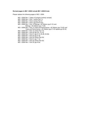
11Stage1 Tab—Nitrous GraphEdit pointGraph Control Edi ngLe click on a data point to enable edi ng for that data point. Le click and drag to adjust the value of the selected datapoint. Click on the graph or another data point to disable the current edit point.Double le click on a data point to set an anchor point, once the anchor point is set le click on another data point andwhen the value is changed the graph will auto fill between the anchor point and the current edit point. Click on the anchorpoint or anywhere in the graph to clear the anchor point.Once the graph is the ac ve control (click on graph) the keyboard may also be used to edit the data points.CTRL S ‐ set edit point to center of graph data.Le and Right keys ‐ move the current edit point le or right.Up Arrow and Down Arrow ‐ adjust current data point up or down in 1% increments.CTRL Up Arrow and CTRL Down Arrow ‐ adjust current data point up or down in .1% increments.ENTER ‐ set anchor point at current edit point. No ac on if there is no current edit point.ESC ‐ clear edit and anchor point(s).Note—the Stage1 Fuel graph ramp will appear in the background to provide a visual reference.Use this feature to Copy the contents of the graph control to other graphcontrols.11
12Important—if the “All Solenoids use Stage1 Nitrous pulse frequency.” op on is checked this se ng will control all nitrousand fuel solenoid frequency (hertz). See Stage1 Setup and Stage2 Setup for more informa on.The solenoid pulse frequency (or also known as Hertz) is how many mes the solenoids open and close when not at 0 or 100 percentopera on. Example ‐ pulse frequency set to 10 hertz and 50 percent, the solenoids would open and close 10 mes per second. Totalme for each pulse 1 / 10 .1 second, total me solenoid would be on .1 * .50% .05 second.Resume Start Percent ‐ This se ng determines the percent the Stage1 Nitrous resumes at if the user has to li the thro le during Ac ‐va on. This se ng is only valid if the Hold And Wait op on is ON. This se ng is used with the Resume Percent per Pulse se ng tobuild a Resume Ramp. If the Resume Start Percent is greater than the current output percent the resume ramp is ignored.Valid range ‐ 10% to 100% in .1% increments. A se ng of 100% disables this feature.Resume Percent per Pulse ‐ This se ng determines the rate at which the Nitrous Resumes if the user li s the thro le during Ac va‐on. This se ng is used with the Resume Start Percent to build a Resume Ramp. This allows the user to adjust how quick the nitrouscomes back on if the Ac va on signal is removed.Example ‐ 10% per pulse would increase the rate 10% for each pulse star ng at the Resume Start Percent se ng. 35% Resume andthen each pulse of the solenoid would increment 10% un l the se ng in the ramp is is achieved. A er the resume ramp is completedthe normal build me ramp is followed.Valid range ‐ 10% to 50% in .1% increments.Quick Ramp Builder ‐ Use this selec on to do quick progressive setups. This feature allows the nitrous to be setup using a Start Per‐centage, Final Percentage, and a Build Time.Start Percentage ‐ This se ng determines the ramp Star ng Percentage. The Start Percent can be less than or greater than the FinalPercent se ng. If the Start Percent is greater than the Final Percent the ramp will progress backwards.Valid range ‐ 0% to 100% in .1% increments.Final Percent ‐ This se ng determines the ramp Final Percentage. The Final Percent can be less than or greater than the Start Percentse ng. If the Start Percent is greater than the Final Percent the ramp will progress backwards.Valid range ‐ 0% to 100% in .1% increments.Build Time ‐ This se ng determines the me it takes for the nitrous to ramp from the Start Percent to the Final Percent se ngs. Ashort Build Time will make the nitrous ramp more aggressive and a longer Build Time will make it less aggressive.Valid range ‐ .200 to 9.900 seconds in .1 second increments.12
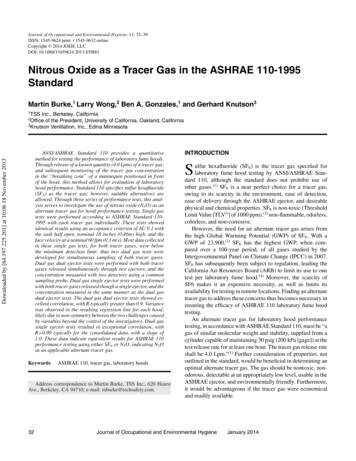
13Stage1 Tab—Fuel GraphStage1 Nitrous rampEdit pointAnchor pointGraph Control Edi ngLe click on a data point to enable edi ng for that data point. Le click and drag to adjust the value of the selected datapoint. Click on the graph or another data point to disable the current edit point.Double le click on a data point to set an anchor point, once the anchor point is set le click on another data point andwhen the value is changed the graph will auto fill between the anchor point and the current edit point. Click on the anchorpoint or anywhere in the graph to clear the anchor point.Once the graph is the ac ve control (click on graph) the keyboard may also be used to edit the data points.CTRL S ‐ set edit point to center of graph data.Le and Right keys ‐ move the current edit point le or right.Up Arrow and Down Arrow ‐ adjust current data point up or down in 1% increments.CTRL Up Arrow and CTRL Down Arrow ‐ adjust current data point up or down in .1% increments.ENTER ‐ set anchor point at current edit point. No ac on if there is no current edit point.ESC ‐ clear edit and anchor point(s).Note—the Stage1 Nitrous graph ramp will appear in the background to provide a visual reference.Use this feature to Copy the contents of the graph control to other graphcontrols.13
14Important—the “All Solenoids use Stage1 Nitrous pulse frequency.” op on must be un‐checked (off) When this feature isenable the Stage2 solenoid frequency (hertz) can be adjusted independently of the Stage1 frequency (hertz).The solenoid pulse frequency (or also known as Hertz) is how many mes the solenoids open and close when not at 0 or 100 percentopera on. Example ‐ pulse frequency set to 10 hertz and 50 percent, the solenoids would open and close 10 mes per second. Totalme for each pulse 1 / 10 .1 second, total me solenoid would be on .1 * .50% .05 second.Resume Start Percent ‐ This se ng determines the percent the Stage1 Fuel resumes at if the user has to li the thro le during Ac va‐on. This se ng is only valid if the Hold And Wait op on is ON. This se ng is used with the Resume Percent per Pulse se ng to builda Resume Ramp. If the Resume Start Percent is greater than the current output percent the Resume Ramp is ignored.Valid range ‐ 10% to 100% in .1% increments. A se ng of 100% disables this feature.Resume Percent per Pulse ‐ This se ng determines the rate at which the Fuel Resumes if the user li s the thro le during Ac va on.This se ng is used with the Resume Start Percent to build a Resume Ramp. This allows the user to adjust how quick the fuel comesback on if the Ac va on signal is removed.Example ‐ 10% per pulse would increase the rate 10% for each pulse star ng at the Resume Start Percent se ng. 35% Resume andthen each pulse of the solenoid would increment 10% un l the se ng in the ramp is is achieved. A er the resume ramp is completedthe normal build me ramp is followed.Valid range ‐ 10% to 50% in .1% increments.Quick Ramp Builder ‐ Use this selec on to do quick progressive setups. This feature allows the fuel to be setup using a Start Percent‐age, Final Percentage, and a Build Time.Start Percentage ‐ This se ng determines the ramp Star ng Percentage. The Start Percent can be less than or greater than the FinalPercent se ng. If the Start Percent is greater than the Final Percent the ramp will progress backwards.Valid range ‐ 0% to 100% in .1% increments.Final Percent ‐ This se ng determines the ramp Final Percentage. The Final Percent can be less than or greater than the Start Percentse ng. If the Start Percent is greater than the Final Percent the ramp will progress backwards.Valid range ‐ 0% to 100% in .1% increments.Build Time ‐ This se ng determines the me it takes for the fuel to ramp from the Start Percent to the Final Percent se ngs. A shortBuild Time will make the fuel ramp more aggressive and a longer Build Time will make it less aggressive.Valid range ‐ .200 to 9.900 seconds in .1 second increments.14
15Stage2 Tab—SetupEnable Stage2—this se ng allows the en re Stage2 system to be turned off/on as desired.Important—when Stage is off the Stage2 Timer output will be disabled as well as any Stage2 se ngs for Timer1 Output and the Relayoutput.Stage2 Delay Timer ‐ this se ng sets the delay me in secondsbefore Stage2 starts a er Ac va on.Valid range ‐ 0.000 to 10.000 in .001 second increments.Enable Stage2 RPM control ‐ this se ng enables a RPM Window func on for Stage2.Note—If the RPM window feature is enabled and the engine isnot running the solenoids can be dry fired for tes ng. Once anRPM signal is present the solenoids will only operate at thedesired RPM range.Stage2 Minimum RPM ‐ this se ng controls the minimum engine RPM that must be achieved before Stage2 will turn On. A se ng of0 will disable the Minimum RPM func on and the Maximum RPM se ng will be used to turn off Stage2 if the engine RPM exceeds these ng.Valid range ‐ 0 to 15,900 RPM in 10 RPM Increments.Stage2 Maximum RPM ‐ this se ng controls the maximum engine RPM that Stage2 remains On. When the engine RPM exceeds thisse ng Stage2 will be turned Off. The Maximum RPM must be at least 100 RPM greater than the Minimum RPM se ng.Valid range ‐ 1000 to 16,000 RPM in 10 RPM increments.Stage2 Synchronize Pulse Frequency ‐ the Stage2 nitrous and fuel solenoids can be configured to func on at the nitrous sole‐noid frequency (hertz) only (both Stage2 outputs synchronized). Or the Stage2 nitrous and fuel solenoid output frequencies (hertz)may be set independently.Note—this op on is only available if the All Solenoids use Stage1 Nitrous pulse frequency is enabled in the Stage1 Setup.IMPORTANT ‐ if you choose to operate the nitrous and fuel solenoids at different frequencies (hertz) you MUST insure that both sole‐noids operate as desired in the delivery of nitrous and fuel to the engine!Informa on ‐ the solenoid pulse frequency (hertz) is how many mes per second the solenoids open and close when not at 0 or 100percent opera on. Example ‐ pulse frequency set to 10 hertz and 50 percent, the solenoids would open and close 10 mes per sec‐ond. Total me for each pulse 1 / 10 .1 second, total me solenoid would be on .1 * .50% .05 second.There are many different styles of solenoids available and they will react differently to changes in the opera ng frequency. It is up tothe user to verify that the solenoids are opening properly with the se ngs used for opera onAs a general rule a lower frequency se ng will allow a solenoid to open properly when a high nitrous pressure is used and a lowstar ng percentage. This is just a general rule, test your se ngs!15
16Stage2 Tab—Nitrous GraphStage2 Fuel rampEdit pointAnchor pointGraph Control Edi ngLe click on a data point to enable edi ng for that data point. Le click and drag to adjust the value of the selected datapoint. Click on the graph or another data point to disable the current edit point.Double le click on a data point to set an anchor point, once the anchor point is set le click on another data point andwhen the value is changed the graph will auto fill between the anchor point and the current edit point. Click on the anchorpoint or anywhere in the graph to clear the anchor point.Once the graph is the ac ve control (click on graph) the keyboard may also be used to edit the data points.CTRL S ‐ set edit point to center of graph data.Le and Right keys ‐ move the current edit point le or right.Up Arrow and Down Arrow ‐ adjust current data point up or down in 1% increments.CTRL Up Arrow and CTRL Down Arrow ‐ adjust current data point up or down in .1% increments.ENTER ‐ set anchor point at current edit point. No ac on if there is no current edit point.ESC ‐ clear edit and anchor point(s).Note—the Stage2 Fuel graph ramp will appear in the background to provide a visual reference.Use this feature to Copy the contents of the graph control to other graphcontrols.16
17Important—the “All Solenoids use Stage1 Nitrous pulse frequency.” op on must be un‐checked (off) and the “Stage1 Ni‐trous and Fuel Solenoids independent frequency.” must be selected for the feature to enabled. When this feature is ena‐ble the fuel solenoid frequency (hertz) can be adjusted independently of the nitrous frequency (hertz).The solenoid pulse frequency (or also known as Hertz) is how many mes the solenoids open and close when not at 0 or 100 percentopera on. Example ‐ pulse frequency set to 10 hertz and 50 percent, the solenoids would open and close 10 mes per second. Totalme for each pulse 1 / 10 .1 second, total me solenoid would be on .1 * .50% .05 second.Resume Start Percent ‐ This se ng determines the percent the Stage2 Nitrous resumes at if the user has to li the thro le during Ac ‐va on. This se ng is only valid if the Hold And Wait op on is ON. This se ng is used with the Resume Percent per Pulse se ng tobuild a Resume Ramp. If the Resume Start Percent is greater than the current output percent the Resume Ramp is ignored.Valid range ‐ 10% to 100% in .1% increments. A se ng of 100% disables this feature.Resume Percent per Pulse ‐ This se ng determines the rate at which the Nitrous Resumes if the user li s the thro le during Ac va‐on. This se ng is used with the Resume Start Percent to build a Resume Ramp. This allows the user to adjust how quick the nitrouscomes back on if the Ac va on signal is removed.Example ‐ 10% per pulse would increase the rate 10% for each pulse star ng at the Resume Start Percent se ng. 35% Resume andthen each pulse of the solenoid would increment 10% un l the se ng in the ramp is is achieved. A er the resume ramp is completedthe normal build me ramp is followed.Valid range ‐ 10% to 50% in .1% increments.Quick Ramp Builder ‐ Use this selec on to do Quick Progressive setups. This feature allows the nitrous to be setup using a Start Per‐centage, Final Percentage, and a Build Time.Start Percentage ‐ This se ng determines the ramp Star ng Percentage. The Start Percent can be less than or greater than the FinalPercent se ng. If the Start Percent is greater than the Final Percent the ramp will progress backwards.Valid range ‐ 0% to 100% in .1% increments.Final Percent ‐ This se ng determines the ramp Final Percentage. The Final Percent can be less than or greater than the Start Percentse ng. If the Start Percent is greater than the Final Percent the ramp will progress backwards.Valid range ‐ 0% to 100% in .1% increments.Build Time ‐ This se ng determines the me it takes for the nitrous to ramp from the Start Percent to the Final Percent se ngs. Ashort Build Time will make the nitrous ramp more aggressive and a longer Build Time will make it less aggressive.Valid range ‐ .200 to 9.900 seconds in .1 second increments.17
18Stage2 Tab—Fuel GraphGraph Control Edi ngLe click on a data point to enable edi ng for that data point. Le click and drag to adjust the value of the selected datapoint. Click on the graph or another data point to disable the current edit point.Double le click on a data point to set an anchor point, once the anchor point is set le click on another data point andwhen the value is changed the graph will auto fill between the anchor point and the current edit point. Click on the anchorpoint or anywhere in the graph to clear the anchor point.Once the graph is the ac ve control (click on graph) the keyboard may also be used to edit the data points.CTRL S ‐ set edit point to center of graph data.Le and Right keys ‐ move the current edit point le or right.Up Arrow and Down Arrow ‐ adjust current data point up or down in 1% increments.CTRL Up Arrow and CTRL Down Arrow ‐ adjust current data point up or down in .1% increments.ENTER ‐ set anchor point at current edit point. No ac on if there is no current edit point.ESC ‐ clear edit and anchor point(s).Note—the Stage2 Nitrous graph ramp will appear in the background to provide a visual reference.Use this feature to Copy the contents of the graph control to other graphcontrols.18
19Important—the “All Solenoids use Stage1 Nitrous pulse frequency.” op on must be un‐checked (off) and the “Stage2 Ni‐trous and Fuel Solenoids independent frequency.” must be selected for the feature to enabled. When this feature is ena‐ble the fuel solenoid frequency (hertz) can be adjusted independently of the nitrous frequency (hertz).The solenoid pulse frequency (or also known as Hertz) is how many mes the solenoids open and close when not at 0 or 100 percentopera on. Example ‐ pulse frequency set to 10 hertz and 50 percent, the solenoids would open and close 10 mes per second. Totalme for each pulse 1 / 10 .1 second, total me solenoid would be on .1 * .50% .05 second.Resume Start Percent ‐ This se ng determines the percent the Stage2 Fuel resumes at if the user has to li the thro le during Ac va‐on. This se ng is only valid if the Hold And Wait op on is ON. This se ng is used with the Resume Percent per Pulse se ng to builda Resume Ramp. If the Resume Start Percent is greater than the current output percent the Resume Ramp is ignored.Valid range ‐ 10% to 100% in .1% increments. A se ng of 100% disables this feature.Resume Percent per Pulse ‐ This se ng determines the rate at which the Nitrous Resumes if the user li s the thro le during Ac va‐on. This se ng is used with the Resume Start Percent to build a Resume Ramp. This allows the user to adjust how quick the fuelcomes back on if the Ac va on signal is removed.Example ‐ 10% per pulse would increase the rate 10% for each pulse star ng at the Resume Start Percent se ng. 35% Resume andthen each pulse of the solenoid would increment 10% un l the se ng in the ramp is is achieved. A er the resume ramp is completedthe normal build me ramp is followed.Valid range ‐ 10% to 50% in .1% increments.Quick Ramp Builder ‐ Use this selec on to do quick progressive setups. This feature allows the fuel to be setup using a Start Percent‐age, Final Percentage, and a Build Time.Start Percentage ‐ This se ng determines the ramp Star ng Percentage. The Start Percent can be less than or greater than the FinalPercent se ng. If the Start Percent is greater than the Final Percent the ramp will progress backwards.Valid range ‐ 0% to 100% in .1% increments.Final Percent ‐ This se ng determines the ramp Final Percentage. The Final Percent can be less than or greater than the Start Percentse ng. If the Start Percent is greater than the Final Percent the ramp will progress backwards.Valid range ‐ 0% to 100% in .1% increments.Build Time ‐ This se ng determines the me it takes for the fuel to ramp from the Start Percent to the Final Percent se ngs. A shortBuild Time will make the fuel ramp more aggressive and a longer Build Time will make it less aggressive.Valid range ‐ .200 to 9.900 seconds in .1 second increments.19
20Timer Stage1 TabStage1 Timer, Timing Retard Control ‐ this se ng configures the Stage1 Timer, 12V out
NPC-2006 Nitrous Power Controller Induction Solutions 16121 Flight Path Dr Brooksville, FL 34604 352-593-5900 Phone 352-593-5901 Fax email: info@inductionsolutions.com