Transcription
IGC 2009, Guntur, INDIAExpansive Soils—Problems and RemediesEXPANSIVE SOILS—PROBLEMS AND REMEDIESB.R. PhanikumarProfessor, Department of Civil Engineering, VIT University, Vellore–632 014, India.E-mail: phanikumar 29@yahoo.comABSTRACT: Expansive soils are one of the examples of tropical soils. These soils pose problems to civil engineers ingeneral and to geotechnical engineers in particular. They cause damage to structures founded in them because of their potential toreact to changes in moisture regime. They undergo severe volume changes corresponding to changes in moisture content. Becauseof their potential to undergo volumetric changes, civil engineering structures such as foundations, retaining walls, pavements,airports, side walks, canal beds and linings are damaged. Various innovative practices have been devised to counteract thevolume change problem and to safeguard the structures. This paper discusses the problems and remedies in detail.1. INTRODUCTION1.1 Expansive Soils and ProblemsExpansive soils pose problems to civil engineers in generaland to geotechnical engineers in particular (Chen 1988). Theycause damage to structures founded in them because of theirpotential to react to changes in moisture regime. They undergosevere volume changes corresponding to changes in moisturecontent. They swell or increase in their volume when theyimbibe water and shrink or reduce in their volume onevaporation of water (Chen 1988). Because of their alternateswelling and shrinkage, they result in detrimental cracking oflightly loaded civil engineering structures such as foundations,retaining walls, pavements, airports, side walks, canal bedsand linings (Chen 1988).2. EXISTING FOUNDATION PRACTICES2.1 Mechanical, Physical and Chemical AlterationsThis involves excavation of expansive soil and replacementwith non-expansive material, where the depth of active zone(depth from ground surface wherein seasonal moisturefluctuations occur) is small and where a suitable replacementmaterial is available. Sand cushion method and CohesiveNon-Swelling (CNS) layer method are very popular.2.1.1 Sand Cushion MethodIn this method, the entire depth of the expansive clay stratumif it is thin, or a part thereof, if it is deep enough, is removedand replaced by a sand cushion compacted to the desireddensity and thickness. It was reported that swelling pressurevaries inversely as the thickness of the sand layer anddirectly as its density. Hence, sand cushions are formed intheir loosest state to avoid the possibility of excessivelyincreasing the swelling pressure without, however, violatingthe criterion of bearing capacity. The basic philosophy of thismethod is that, in monsoon, the saturated sand occupies lessvolume, accommodating some of the heave of underlyingexpansive soil, and in summer, partially saturated sand bulksand occupies the extra space left by the shrinkage of the soil.2.1.2 Cohesive Non-Swelling (CNS) Layer MethodIn this method, about top 1 m to 1.2 m of the expansive soilis removed and replaced by a cohesive non-swelling soillayer. According to Katti (1978), with saturation ofexpansive soil cohesive forces are developed up to a depth ofabout 1.0–1.2 m and counteract heave. CNS layer creates anenvironment similar to that around 1 m deep in an expansivesoil with equivalent cohesion to counteract heave.In physical alteration, granular material is mixed with expansiveclay to minimize heave. However, the permeability of theresulting blend would be more than that of the expansive soilresulting in a faster ingress of water into the soil. Chemicalalteration involves addition of chemicals to expansive clay toreduce heave by altering the nature of expansive clay minerals(Chen 1988). Lime treatment of expansive soils is the mostwidely used technique and the most effective technique ofchemical alteration to minimize volume changes and to increasethe shear strength of foundation expansive soils. The usefulnessof the treatment depends on the reactivity of the soil to limetreatment and the extent of dispersion of lime into the soil.In pavements, a technique called Lime-Slurry PressureInjection (LSPI) is also used for minimizing swelling ofsoils. In this technique, lime-slurry is injected into drill-holesunder a pressure of 15 kg/cm2 (Chen 1988). In this technique,lime slurry penetrates into the fissures in the soil mass to asufficient depth (usually 8 to 10 feet), and the lime-filled seamshelp control the soil water content, reduce volumetric changesand increase soil strength. However, for LSPI to be an effectivetechnique, the expansive clay soil must contain an extensivenetwork of fissures. Otherwise, lime cannot penetrate into therelatively impermeable soil to an appreciable distance fromthe injection hole to form a continuous lime seam moisture907
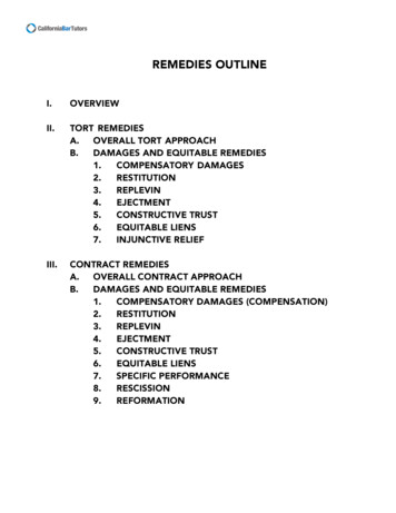
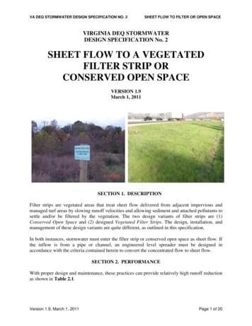
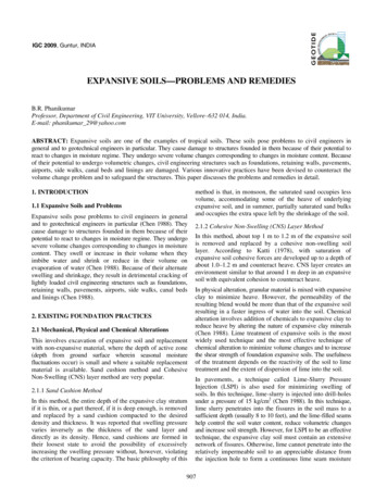
Expansive Soils—Problems and RemediesAddition of calcium chloride (CaCl2) to expansive soil hasalso proved efficacious in altering the swelling properties ofthe soil. Calcium chloride is a hygroscopic material and hence,is pre-eminently suited for stabilization of expansive soils,because it absorbs water from the atmosphere and preventsshrinkage cracks occurring in expansive soils during summer.Addition of calcium chloride to expansive soils reducedPlasticity Index (PI), free Swell Index (FSI%), swell potentialand ( H/H, %) and swelling pressure, ps, significantly. Anotheradditive that has been found to be quite promising in reducingthe swelling characteristics and improving the engineeringbehavior of expansive soils is fly ash. The efficacy of fly ashas an additive to expansive soils in ameliorating their propertieswas reported.granular pile was varied as 50%, 60% and 70%. The heightof the expansive clay bed and the granular pile-anchor werethe same in all the tests. A square mild steel plate of size 100mm 100 mm was used as the surface footing in the heavetests (set up not shown here). The rate and amount of heaveof the unreinforced clay bed were compared with those of theclay bed reinforced with granular pile-anchor. Theunreinforced expansive clay bed attained a final heave of 9%in 9 days. However, the heave of the expansive clay bedreinforced with granular pile-anchor attained a reducedamount of heave of 1.15% in a short period of 3 days (seeFig. 1). As surface area of the GPA increased, heave of theclay bed decreased (see Fig. 2).10987% Heavebarrier Lime-soil columns were also tried to stabilizeexpansive clays in-situ. It was reported that diffusion of limeinto the ambient soil is effective up to a radial distance ofabout 3 times the diameter of the lime-soil column.2.2 Special Foundation TechniquesThe problem of heave or uplift of foundations caused byexpansive soils is one of tension developed in the soil due toswelling. Hence, tension-resistant foundations are requiredfor counteracting the heave problem. Various special foundationtechniques such as drilled piers, belled piers (Chen 1988) andunder-reamed piles are all tension-resistant foundations.A total of 81 laboratory model tests were conducted forstudying the heave behaviour. The relative density of the5S4S'3Dry unit weight of soil 14 kN/mwi of soil 14%Length of pile 300mmDiameter of pile 40mmRelative density 0.6321001000 2000 3000 4000 5000 6000 7000 8000 9000 10000 11000 12000Time (minutes)Fig. 1: Rate of Heave2.4Length 300mmLength 400mmLength 500mm2.01.6S'Granular Pile-Anchor (GPA) technique has been a recentinnovation over the conventional granular pile, modified intoan anchor (Phanikumar 1997). This paper discusses GPAsystem in detail as it is the latest most successful tensionresistant foundation system. Laboratory testing performed tostudy the efficacy of Granular Pile-Anchor Foundation(GPAF) system in reducing the amount of heave and improvingthe engineering behavior of expansive clay beds gave promisingresults. The effect of length, diameter and relative density ofGPAs was studied. In a GPA, the foundation is anchored atthe bottom of the granular pile to a mild steel plate through amild steel rod to render the granular pile tension-resistant bythe effect of anchor, which is able to counteract the upliftforce exerted on the foundations. In a granular pile-anchor,the resistance to uplift is developed mainly due to, (i) theweight of the granular pile acting in the downward directionand (ii) uplift resistance due to friction mobilized along thecylindrical pile-soil interface, and precludes the possibility ofheave of foundations. The upward force acting on thefoundation is because of swelling of the expansive soil onimbibition of water. The resisting force acting in thedownward direction and counteracting the uplift force is dueto friction mobilized along the pile-soil interface, whichdepends on the shear strength parameters of the interface.Dry unit weight of soil 14 kN/m3wi of soil 14%61.2Granular pileRelative density 0.60.80.40.0024681012141618Lg/DgFig. 2: Effect of l/d Ratio on % Heavefor a Given LengthThe pull-out capacity of the granular pile-anchors increasedwith increasing length of the pile-anchor and relative densityof the granular material. For a pile of length of 250 mm, theload for 30 mm upward movement was about 250 N,whereas for a pile of length of 350 mm, it was equal to about908
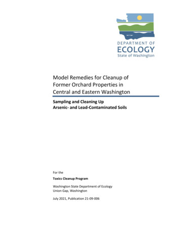
Expansive Soils—Problems and Remedies510 N, indicating an increase of about 100%. The % increasein the pull-out load when the relative density was increasedfrom 50 to 70% was about 30% for an upward movement of30 mm (see Figs. 3 and 4). It was found that the load-carryingcapacity of the expansive clay bed also increased by theinstallation of granular pile-anchors. The loading intensityfor a settlement of 25 mm in the case of the reinforced claybed increased by 2½ times over that for the same settlementin the case of the unreinforced clay bed (see Fig. 5).60Granular pileDiameter 30 mmRelative density 0.650used in this investigation was collected from a depth of 1.5 mbelow the ground level in Amalapuram, Andhra Pradesh,India. The soil was a highly swelling soil with Free SwellIndex (FSI) of 180%. It was a CH soil. Table 1 shows theindex properties of the expansive soil. The maximum dryunit weight was 14 kn/m3 and the optimum moisture contentwas 27%. The granular material used for the installation ofgranular piles was a blend of 20% stone chips and 80% coarsesand. The particle sizes of stone chips and coarse sand werethe same as the granular material used in laboratory testing.It may be mentioned here that all the granular piles in the testprogram were compacted at a relative density of 70%.24001234567891011030Granular pile aloneComposite ground (soil and pile)Soil alone620Length 0.35m12Settlement (mm)Load x 10 (N)Stress (kN/m )Length 0.30m10Length 0.25m00102030405060Deformation (mm)18243036Fig. 3: Influence of Length of Granular Pile-Anchoron the Pullout Behavior424880Fig. 5: Stress-Settlement CurvesGranular pileDiameter 30 mmLength 0.30 m70Table 1: lgp/dgp Ratios of Granular Pile-AnchorsDiameter ofLength of the pile, mmthe pile, mm5007501000Load x 10 (N)60504010057.5Relative density 0.71503.3356.67Relative density 0.62002.53.75530201010Relative density 0.5Granular pile-anchor system was also tested in fieldconditions by performing in situ tests (Rao et al. 2004). Itwas found that heave reduction and the rate of heave weresimilar to those obtained in the laboratory model tests.In all the tests the expansive clay beds were compacted at aplacement water content of 15% and dry unit weight of14 kN/m3. The thickness of expansive clay beds was fixed at1000 mm. the length of the granular pile-anchor (lgp) wasvaried as 500, 750 and 1000 mm. for each length, thediameter of granular pile-anchors (dgp) was varied as 100,150 and 200 mm. Hence, the range of the length to diameterratio (lgp/dgp) of granular pile-anchors varied from 2.5 to 10.Table 1 shows the l/d ratios of the GPAs tested. Heave of theclay bed at different depths and radial distances from thecenter of the granular pile-anchor was also continuouslymonitored as the clay bed was inundated.An extensive test program was conducted in situ for establishingthe efficacy of granular pile-anchors in expansive clay beds.Amount of heave and rate of heave were observed both in thecase of un-reinforced expansive clay beds and clay bedsreinforced with granular pile-anchors. The expansive soilThe un-reinforced expansive clay bed attained a final amountof heave of 154 mm or final % heave of 15.4%. As there wasno technique provided in the clay bed for arresting heave, theclay bed heaved to its fullest extent. However, in the case ofclay beds reinforced with GPAs in situ, heave was reduced0010203040Deformation (mm)5060Fig. 4: Effect of Relative Density on thePull-Out Behavior3. FULL SCALE TESTING ON GPA SYSTEM909
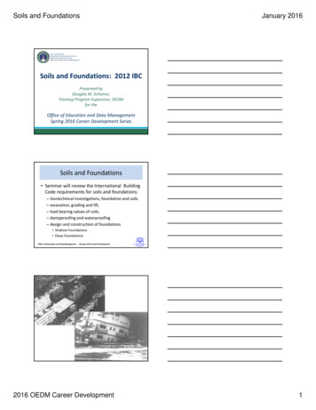
Expansive Soils—Problems and Remediesconsiderably. The respective amounts of reduced heave ofclay beds reinforced with GPAs of length 1000 mm anddiameters 100,150 and 200 mm were 48, 27 and 15 mm. Hence,the final % of heave was 4.8%, 2.7% and 1.5% in the abovecases (Phanikumar et al. 2007). The amount of heave wasreduced quite effectively by reinforcing the clay beds withGPAs due to the effect of anchorage and shear resistancemobilized along the pile-soil interface (see Table 2). Regardingthe rate of development of heave, the un-reinforced expansiveclay bed required about 210 days or 7 months of continuouswetting to attain the final amount of heave (154 mm), whereasthe clay bed reinforced with granular pile-anchors required amuch less time. For example, the clay bed reinforced withgranular pile-anchors 1000 mm long and 100, 150 and 200mm in diameter required a time period of 120 days or 4 months.The expansive clay beds reinforced with gpas adjusted quicklyto moisture changes. In all the cases it was found that theamount of heave decreased with depth from the top, reachingzero amount of heave at the bottom of the pile-anchor or claybed. It may be mentioned here that the length of the pile-anchorand the thickness of the clay bed are equal in this case.Table 2: Reduced % heave (S′) of Clay Beds by GPAs(Heave of un-reinforced expansive clay bed 154 mm)Diameterof GPA(mm)100150200Length of GPA, mm5007501000756346644738482715However, in the case where the length of the pile-anchor wasless than thickness of the clay bed, some amount of heave wasrecorded at the bottom of the pile-anchor. This was becausethe expansive clay beneath the base of the pile-anchorswelled. Heave increased with increasing radial distance fromthe center of the granular pile-anchor in curvilinear fashion.Further, a test program was conducted in the field ongranular pile-anchors embedded in expansive clay beds. Thereinforced clay beds were saturated and the amount and rateof heave were observed and compared with those of theunreinforced clay beds. After complete saturation, pulloutload was applied on the granular pile-anchor and the upwardmovement noted. In total, nine field pullout tests wereconducted on single granular pile-anchors varying the lengthand diameter of granular pile-anchor. One pullout test wasconducted to study the group behavior also (Rao et al. 2007).Figure 6 shows the pullout load-upward movement curvesfor single granular pile-anchors of a uniform diameter of 200mm with lengths varying as 500, 750 and 1000 mm. Thecurves indicate the influence of length of granular pile-anchor.All the granular pile-anchors were tested up to failure. Thecurves presented in the figure show that the failure pulloutload increased with increasing length of the granular pileanchor. The curves also indicate that, at all stages of loading,the upward load required to be applied on the granular pileanchor to cause a given upward movement increased withincreasing length of granular pile-anchor. However, it maybe observed that, up to an applied uplift load of 4 kN, therewas no significant upward movement in the granular pileanchors. This is because of the weight of the granular pileanchor (about 0.5 kN) and the shear resistance mobilized inthe downward direction along the cylindrical pile-soilinterface (about 3 kN) because of the anchorage. Figure 7shows the pullout behavior of granular pile-anchors of 1000mm length but of diameters varying as 100, 150 and 200mm. The curves in the figure reflect the effect of diameter ofGranular Pile-Anchor (GPA). All the curves in the figureshow that the failure pullout load increased with theincreasing diameter and weight of the granular pile-anchor.The applied upward load was observed to increase withincreasing diameter of granular pile-anchor at all stages ofthe test as the resistance to uplift increased with increasingsurface area of the pile-soil interface (Rao et al. 2007).Figure 8 shows the variation of failure pullout load (kN) withthe l/d ratio of Granular Pile-Anchors (GPA). The curvespresent the data for different lengths of the granular pileanchors. For a given l/d ratio the failure pullout loadincreased with increasing length of the granular pile-anchor.This is attributed to the increase in the pullout resistance withincreasing surface area of the granular pile-anchor. Similarly,for a given length of the Granular Pile-Anchor (GPA), thefailure pullout load increased with increasing diameter ordecreasing l/d ratio. Increasing diameter increases the surfacearea and pile-anchor weight and consequently uplift resistanceand results in increased failure pullout load (Rao et al. 2007).Figure 9 shows, by comparison, the pullout behavior of thelaboratory scale granular pile-anchor and field scale granularpile-anchor. In both the cases, the granular pile material wascompacted to a relative density of 70%. Similarly the l/d ratioof granular pile-anchor in both the cases was equal to 10. Whilethe diameter and length of laboratory scale granular pileanchor were 30 and 300 mm, those of the field scale granularpile-anchor were 100 and 1000 mm, respectively. Thethickness of the expansive clay bed was equal to the lengthof the Granular Pile-Anchor (GPA) in both the cases. Thecurves in the figure show that the uplift load (kN) required tobe applied for any given upward movement (mm) of thegranular pile-anchor was significantly higher in the fieldscale Granular Pile-Anchor (GPA) than that in the case oflaboratory scale Granular Pile-Anchor (GPA).910
Expansive Soils—Problems and RemediesThe large variation in the behavior of the Granular PileAnchors (GPAs) in the laboratory study and the field studywas due to the scale effect (Rao et al. 2007).Pullout Load (kN)l 1000 mm12l 750 mm8l 500 mm4001020304050Upward Movement (mm)Fig. 6: Pullout Behavior of Granular Pile-Anchorsof Diameter 200 mmPullout laod (kN)16128Diameter 100 mm 150 mm4 200 mm001020304050Figure 10 shows, by comparison, the variation of failurepullout load with l/d ratio of granular pile-anchors inlaboratory scale study and field scale study. The data pertainto three field scale Granular Pile-Anchors (GPA) of length1000 mm (diameter 100, 150 and 200 mm) and threelaboratory scale Granular Pile-Anchors (GPA) of length 500mm (diameter 30, 40 and 50 mm). The expansive clay bedsin both the cases were compacted at placement water contentof 15% and dry unit weight of 14 kN/m3. All the granularpiles were compacted to a relative density of 70%.Irrespective of the l/d ratio the failure pullout load for fieldscale granular pile-anchors was much higher than that forlaboratory scale granular pile-anchors. This was because ofthe increased surface area, frictional resistance and theweight of granular material in the case of field scale granularpile-anchor and the consequent increase in uplift resistance.Moreover, the lateral swelling pressure of expansive clay bedin situ, which confines the Granular Pile-Anchor (GPA) isalso significantly high compared to that in the laboratoryscale expansive clay bed (Rao et al. 2007).Upward movement (mm)Failure pullout load (kN)for field scale GPAFig. 7: Pullout Behavior of Granular Pile-Anchorsof 1000 mm LengthFailure pullout load (kN)16160.92120.8880.84Field scale GPA12Failure pullout load (kN)for laboratory scale GPA16Laboratory scale GPA40.8286101418l 500 mml 750 mml/dl 1000 mmFig. 10: Variation of Failure Pullout Load with l/d in Fieldand Laboratory Scale Granular Pile-Anchors424681012l/dFig. 8: Variation of Failure Pullout Load with l/d Ratioof Granular Pile-Anchor840Pullout behavior(field scale)Pullout behavior(laboratory scale)4200Failure pullout load (N)for laboratory scaleGPA60Failure pullout load(kN) for field scaleGPA120010203040Upward movement (mm)Fig. 9: Comparison of Pullout Behavior of Laboratory Scaleand Field Scale Granular Pile-Anchors (l/d 10; Dr 70%)Figure 11 shows, by comparison, the pullout behavior of thegranular pile-anchor when tested single and when testedunder group effect. The granular pile-anchor under groupeffect resulted in increased uplift load for a given upwardmovement in comparison to that of a single granular pileanchor tested. This is because of the influence of the granularpile-anchors in the group on the test granular pile-anchor. Asheave of the expansive clay bed was reduced significantly onthe installation of group of granular pile-anchors, which alsoact as tension members, there was not much reduction in thedry unit weight of the expansive clay bed. As a result thepile-soil interface friction for the group would be much morethan in the case of the single granular pile-anchor. This alsoresulted in a higher lateral swelling pressure (confining thetest granular pile-anchor radially) than in the case of a singlegranular pile-anchor. There is an arching action between the911
Expansive Soils—Problems and Remedies200-5-10Stress (kN/m )4006008001000un-reinforced expansive clay bedcomposite ground (Phanikumar et al.2004) - laboratory scalecomposite ground - in situ (150 mm diagranular pile-anchor)p ile-anchor alone ( Phanikumar et al.2004) - laboratory scalep ile-anchor alone -in situ (150 mm -40-45-50Fig. 11: Stress-Settlement Behavior of Un-ReinforcedExpansive Caly Bed and Clay Beds Reinforced withGranular Pile-AnchorsField-scale plate load tests were also conducted on in situGPAs installed in expansive clay beds to study the compressiveload response (Rao et al. 2007). Load-settlement behaviorwas studied in the following cases:(a) un-reinforced expansive clay bed(b) composite ground with the test plate spreading on boththe granular pile-anchor and the expansive clay bed(c) Granular Pile-Anchor (GPA) alone with the test platebearing only on the granular pile-anchor, and(d) expansive clay bed reinforced with a group of granularpile-anchors.Figure 11 shows the stress-settlement curves for the unreinforced expansive clay bed, the composite ground (granularpile-anchor and expansive clay bed together) and GPA alone.The data plotted in the figure show that the clay bed reinforcedwith granular pile-anchor gave an improved compressiveload response in comparison to the un-reinforced clay bed asreflected in the stress-settlement curve for composite ground.For example, the stress required to cause a settlement of25 mm in the un-reinforced expansive clay bed was200 kN/m2 whereas the stress required to cause the sameamount of settlement in the case of composite ground was500 kN/m2. This indicates that the load-carrying capacity ofthe clay bed reinforced with granular pile-anchor improvedby 150%. The compressive load response for the expansiveclay bed reinforced with group of granular pile-anchorsshowed a significant improvement in load-carrying capacityover the un-reinforced clay bed. Though the test plate wasplaced on saturated clay alone in both the cases, the resistanceto compressive load offered by the clay reinforced with groupof granular pile-anchors was higher than that by un-reinforcedclay. Heave was reduced significantly in the expansive claybed reinforced with granular pile-anchors. This means thatthe decrease in dry unit weight or the increase in void ratio ofthe clay bed owing to heaving of clay was arrested bygranular pile-anchors. Hence, the reinforced clay bed couldresist the compressive load better than the un-reinforced claybed wherein complete heave occurred leading to significantreduction in dry unit weight or increase in void ratio. Thestress required to cause a settlement (d) of 25 mm in unreinforced expansive clay bed was 200 kN/m2, whereas itincreased to 330 kN/m2. Figure 12 shows the effect of lengthof GPAs on stress-settlement behaviour for a given diameterof 150 mm. The figure shows the stress-settlement curves forun-reinforced clay bed and clay bed reinforced with singlegranular pile-anchors having different lengths (500 mm,750 mm and 1000 mm) but uniform diameter of 150 mm. Itmay be mentioned here that the data shown in Figure 12pertain to load tests performed on granular pile-anchors alone(test plate bearing only on the granular pile). Increasinglength of the GPA resulted in higher amount of stress for agiven settlement (d). For example, the stress required for25 mm settlement was respectively 360, 505, 690 kN/m2 for500 mm, 750 mm and 1000 mm long granular pile-anchors.A similar trend was observed with increasing length of GPA2Stress (kN/m )01002003004005006007008009000un-reinforced expansive clay bedSettlement (mm)granular pile-anchors, which offers more resistance to uplift.The uplift load required to be applied on the granular pileanchor to cause an upward movement of 25 mm was 13.7 kNwhen tested under group effect as against an uplift load of11.25 kN for the same amount of upward movement of25 mm when tested single. This indicated a percentage increaseof 22.22% in the applied uplift load when the granular pileanchor was tested under group effect. The failure pulloutload of the granular pile-anchor when tested under group was18 kN as against a failure pullout load of 12 kN for the granularpile-anchor when tested single, indicating an improvement of50% in the failure pullout load (Rao et al. 2007).-103 - group granular pile-anchorscomposite ground (150 mm diagranular pile-anchor)-20-30-40-50Fig. 12: Stress-Settlement Behavior of UnrienforcedExpansive Clay Bed and Clay Bed Reinforced with Group ofGranular Pile-Anchors912
Expansive Soils—Problems and Remediesfor other diameters also. Figure 12 shows the stresssettlement behavior of un-reinforced expansive clay bed andclay bed reinforced with group of GPAs.Phanikumar, B.R. (1997). “A Study of SwellingCharacteristics of and Granular Pile-Anchor FoundationSystem in Expansive Soils”, Ph.D Thesis Submitted to JNTechnological University, Hyderabad, India.4. CONCLUSIONRao, A.S., Phanikumar B.R., Suresh, K. and Sudhakar, V.(2004). “Compression Test on Granular Pile-AnchorsEmbedded in Expansive Soils”, Indian GeotechnicalConference, Warangal, India, pp. 141–144.Rao, A.S., Phanikumar, B.R., Babu, R.D. and Suresh, K.(2007). “Pullout Behavior of Granular Pile-Anchors inExpansive Clay Beds In-situ”, Journal of Geotechnicaland Geoenvironmental Engineering, Vol. 133, Issue 5, pp.531–538.Expansive soils, being problematic soils with their innatepotential for severe volume changes upon changes in moisturecontent, need to be treated with special techniques. Sandcushion, CNS layer, chemical and physical alteration techniqueshave been successful. Granular Pile-Anchor (GPA) techniquehas been a recent technique developed with some innovationintroduced into granular piles. GPA has met with considerablesuccess as observed in both laboratory and field scale tests.Heave was reduced significantly and the surrounding soilwas found improved. Results of pullout tests and compressiveload tests indicated that length, diameter and relative density ofGPA govern heave and engineering behaviour of GPA system.REFERENCESChen, F.H. (1988). Foundations on Expansive Soils, ElsevierScientific Publishing Company, Amsterdam.Rao, A.S., Phanikumar, B.R. and Suresh, K. (2008).“Compressive Load Response of Expansive Clay BedsReinforced with Granular Pile-Anchors In-situ”, GroundImprovement, Vol. 161, No. 3, pp. 121–129.Phanikumar, B.R., Rao, A.S. and Suresh, K. (2008). “In situBehavior of Expansive Clay Beds Reinforced with GranularPile-Anchors”, Ground Improvement (in press-proofchecked).913
A total of 81laboratory model tests were conducted forload for 30 mm upward movement was about 250 N, studying the heave behaviour. The relative density of thewhereas for a pile of length of 350 mm, it was equal to about granular pile was varied as 50%, 60% and 70%. The height of the expansive clay bed and the granular pile-anchor were