Transcription
A Maxim Integrated Products Brand73S1215F, 73S1217FUSB CCID GuidelinesSeptember 14, 2009Rev. 2.10AN 12xxF 028Library Rev. 4.00(DFU)Code/Firmware Rev. TSC12xx.2.10
73S1215F, 73S1217F USB CCID GuidelinesAN 12xxF 028Maxim cannot assume responsibility for use of any circuitry other than circuitry entirely embodied in a Maxim product. No circuitpatent licenses are implied. Maxim reserves the right to change the circuitry and specifications without notice at any time.Maxim Integrated Products, 120 San Gabriel Drive, Sunnyvale, CA 94086 408- 737-7600 2010 Maxim Integrated ProductsMaxim is a registered trademark of Maxim Integrated Products.
AN 12xxF 02873S1215F, 73S1217F USB CCID GuidelinesTable of ContentsFigures . 4Tables . 41Introduction . 52Overview . 53CCID Application Firmware. 63.1 CCID Application Build Environments . 63.2 Suspend and Resume Processing . 93.3 Endpoint 0 Processing . 93.4 Card Slot Status Processing via (interrupt) Endpoint 2 . 93.5 CCID Command Processing . 93.6 Command Error Codes . 103.7 Mechanical Features Porcessing. 103.8 Escape Command Processing . 104Driver Selection and Installation . 115Smart Card Application . 125.1 Multiple Slot Operation . 125.2 Sending Escape Commands . 135.2.1 EscapeCommand – LCD Control: 0x31 . 165.2.2 EscapeCommand – KeyPad Control:0x32 . 165.2.3 Escape Command – EMV Level 1 Test Control: 0x33 . 175.2.4 EscapeCommand – LED Control: 0x34 . 235.2.5 EscapeCommand – DFU Detach: 0x41 . 235.2.6 EscapeCommand – Serial Interface Control: 0x50 . 246Acronyms. 257Related Documentation . 268Contact Information . 26Revision History . 27Rev. 2.103
73S1215F, 73S1217F USB CCID GuidelinesAN 12xxF 028FiguresFigure 1: Overview of the 73S12xx CCID Software . 5Figure 2: Add New Hardware Wizard Showing Microsoft and TSC CCID Drivers . 11Figure 3: Add EMV Test Mode . 19Figure 4: MasterCard Loopback Test . 20Figure 5: VISA-1 Loopback Test . 21Figure 6: VISA-2 Loopback Test . 22TablesTable 1: CCID Firmware Source Code Modules. 7Table 2: CCID SET DEVICE MODE Device Request . 9Table 3: Windows Smart Card APIs used in the SmartCard Sample Application . 12Table 4: Extended Features . 144Rev. 2.10
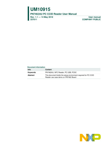
AN 12xxF 02873S1215F, 73S1217F USB CCID Guidelines1 IntroductionThis document contains guidelines for the use of the TSC73S12xxF in a USB environment, particularly Microsoft Windows XP and PC/SC. The intent of this application note is to aid customers in thedevelopment of Smart Card Reader applications specific to their environment. It is not intended as areference document for the software mentioned in this document.2 OverviewFigure 1 shows an overview of the 73S12xxCCID Software. TSC has provided an embedded CCIDfirmware application that is compliant with the USB CCID Class Specification of the USB Device ClassSpecification for USB Chip/Smart Card Interface Devices Specification, Revision 1.1. The firmware hasbeen developed on the TSC 73S12xxF Evaluation Board. The firmware is provided in the form of ANSI Csource code and Keil uVision2/3 project files so that the customer may use them to modify and enhancethe application to meet their requirements.In the Windows environment, the customer may employ either the Microsoft-supplied CCID USB clientdriver or the TSC enhanced CCID USB client driver. The TSC driver offers additional hardware supportfor multiple card slots, LCD operation and PIN pad input.Figure 1: Overview of the 73S12xx CCID SoftwareOn the Windows side, the customer develops application software using the Windows Smart Card API toaccess/control the reader.Rev. 2.105
73S1215F, 73S1217F USB CCID GuidelinesAN 12xxF 0283 CCID Application FirmwareOnce the 73S12xxF Development Kit is installed, the CCID Application Firmware is contained in the CCIDUSB folder. Refer to the 73S12xxF Software User’s Guide description of the contents of this installationdisk. The firmware is delivered in the form of source code and Keil uVision (.uv2 or .uv3) project files.Customers can modify and build this software and download .hex files to the 73S12xxF Evaluation orDemo Board as detailed in the 73S12xxF Software User’s Guide, the 73S12xxF Evaluation Board User’sGuide, and the Teridian Flash Programming Tool.3.1CCID Application Build EnvironmentsStarting from revision 2.00, the CCID Application with the DFU Boot Loader feature was partitioned toreside starting at address 0x1802 instead of the previous address of 0x0000. The CD ROM version 2.00built for CCID USB version 2.00 has two distinct flavors: with the DFU Boot Loader and without the DFUBoot Loader (same as previous releases). Prior CCID projects (without the Boot Loader) remain thesame. The CCID DFU project file setup to accommodate the DFU Boot Loader feature has the followingchanges:1. The Application starting address is set at 0x1802 as shown below:2. The Interrupt Vector address is also set to start at 0x1802 as shown below. The DFU directive(circled in black below) is used to specifically select the DFU feature into the build. The LEDMGTdirective (circled in red below) indicates the new LED0 control feature as described in Section 5.2.4.6Rev. 2.10
AN 12xxF 02873S1215F, 73S1217F USB CCID Guidelines3. The LAPI and HAPI libraries are built specifically for DFU to stay clear of the DFU Flash area. Thus,the CCID DFU project file is also setup to link to the DFU flavored libraries as shown below:The CCID firmware application is divided into functional source code modules as illustrated in Table 1.Customers are encouraged to browse the source files to better understand how they work. Special careshould be taken when modifying these source files. Customers are discouraged from modifying coderelated to the USB CCID class processing found in ccidusb.c and ccidprot.c. Specific parts of the codethat may be customized are identified in the following sections.Table 1: CCID Firmware Source Code ModulesFunctional AreaModulemain() and init functionccidtsc.cCCID USB layerccidusb.cCCID Protocol Layerccidprot.cEnhanced CCID support for pinpad and LCDccidhid.cUtility functionsccidutil.cRev. 2.107
73S1215F, 73S1217F USB CCID GuidelinesAN 12xxF 028The USB CCID Class Specification specifies a USB CCID class descriptor, which is used to present allSmart Card Reader features to the host computer. The CCID firmware application employs the TSC ICCHAPI (detailed in the 73S12xxF Smart Card Terminal Controller Family Software User’s Guide) to provideSmart card functionality. The Smart Card HAPI layer is multi-standard compliant and encapsulates agreat deal of functionality. This is reflected in the contents of the USB CCID class descriptor as defined inccidusb.c. The descriptor contents specify, among other things, Short and Extended APDU level oftransfer, automatic voltage selection, automatic protocol parameters selection and automatic clockfrequency and data rate change.USB communications are achieved with the use of the USB LAPI functions as described in detail in the73S12xxF Smart Card Terminal Controller Family Software User’s Guide. The CCID application is asingle threaded C program whose main() function is placed in ccidtsc.c. The main() function contains ado.while(1) loop which polls the various external events and performs the necessary processing. First,the main loop calls the USB OUT 1() LAPI to check for data reception on the CCID bulk command pipe.If a CCID command has been received this is processed in CCID CommandDispatch() as described inSection 3.4. If no data is present on the bulk pipe as indicated by USB OUT1() returns RX PENDING.The firmware then checks for the following: The status of the EP0 control pipe using CheckEP0Status() as described in Section 3.2. The status of ICC slots using CheckCardStatus() as described in Section 3.3. The status of USB state for suspend/reset/resume as described in Section 3.1.8Rev. 2.10
AN 12xxF 0283.273S1215F, 73S1217F USB CCID GuidelinesSuspend and Resume ProcessingThe functions uReset(), uSuspend() and uResume() in ccidusb.c are callback functions for the USB LAPIthat are set up during initialization with a call to USB Init(). The functions are called by the LAPIsubsystem when USB suspend and resume conditions occur on the bus. In the CCID applicationfirmware these functions are used to power down/up the ICC and PIN pad to meet USB suspend powerrequirements.The customer application may use these callback functions to power down/up additional componentsand/or to perform additional suspend/resume processing.3.3Endpoint 0 ProcessingUSB device requests are made over the control pipe on endpoint 0. The status of EP0 is checked bycalling the LAPI USB Status() from within the CheckEP0Status() function in ccidtsc.c LAPI returns anenumerated value indicating what type of request, if any, has been received on the control pipe. Refer tothe 73S12xxF Smart Card Terminal Controller Family Software User’s Guide for further information on theUSB Status() LAPI.The CheckEP0Status() function handles both class device requests (ABORT) and TSC vendor specificdevice requests detailed below. The customer should not need to modify any of this code and thefollowing is provided for information only.The CCID SET DEVICE MODE device request is used to set the device mode to either Microsoft CCIDmode or TSC enhanced CCID mode. The device request control bytes are defined in Table 2. Thefirmware sets a global variable called gFirmwareMode. This global is used throughout the firmware tocontrol access to multiple slots and enhanced features. In Microsoft CCID mode (default firmware mode),only one slot (slot 0) is supported and all of the enhanced features such as LCD and PIN pad aredisabled.Table 2: CCID SET DEVICE MODE Device ta01000000CCID SET DEVICE MODE (0)Device Mode*00none* 0 Microsoft CCID mode, 1 TSC Enhanced CCID mode3.4Card Slot Status Processing via (interrupt) Endpoint 2Thestatus of the card slots is checked by calling the ICC Status() HAPI from within theCheckCardStatus() function in ccidtsc.c. The USB CCID Class Specification describes how the hostcomputer is notified of card slot insertions and removals and the customer should not need to modify thiscode.3.5CCID Command ProcessingCCID bulk command processing is performed in the CCID CommandDispatch function contained inccidusb.c. This function contains a large switch statement with cases for all of the CCID Bulk commandresponse pairs detailed in the USB CCID Class Specification. This source module also contains all themessage-specific processing, including accesses to the ICC HAPI. The customer is strongly discouragedfrom modifying any of this code, since this code has been thoroughly tested using the Microsoft HCT andDTM test tools and is standard-compliant. However the customer may modify the Mechanical and EscapeCommand processing as detailed below.Rev. 2.109
73S1215F, 73S1217F USB CCID Guidelines3.6AN 12xxF 028Command Error CodesCCID bulk command is processed and executed. An error code is returned for each command accordingto the USB CCID Class Specification. Teridian added a few more error codes, mostly following anescape command. The error codes provided in the accompanied CCID source code are defined asfollows:// the following #defines are used on the bError byte#define CMD ABORTED0xff#define ICC MUTE0xfe#define HW ERROR0xfb#define BAD ATR TS0xf8#define BAD ATR TCK0xf7#define UNKNOWN ESC CMD0xff#define KEYPAD TIMEOUT0xf93.7Mechanical Features PorcessingSince the 73S12xxF evaluation board does not have any mechanical features, no specific mechanicalprocessing is performed in the CCID firmware. Customers who wish to develop readers with mechanicalfeatures are directed to the CCID Mechanical() function in ccidusb.c. The decoding software for thisfunction has switch cases for LOCK CARD and EJECT CARD and has provided stub functions(LockCard() and EjectCard()) for these two cases. The stub functions simply return success and thecustomer should place any mechanical processing code in these functions.The USB Device Class Specification for USB Chip/Smart Card Interface Devices Specification, Revision1.1 only supports LOCK CARD and EJECT CARD, although other mechanical functions are defined.The customer should add any other required mechanical functions to the switch statement contained inCCID Mechanical() and add handler functions as required.3.8Escape Command ProcessingThe USB CCID Class Specification provides the PC to RDR Escape bulk command to allow card readervendors to send and receive custom data between the host computer and reader. The CCID applicationfirmware provides a handler function in ccidusb.c called CCID Escape(). This handler can be used toimplement additional customization features such as LCD and Keypad as defined outside the scope ofCCID specification. Any customer-specific escape processing should be added to this handler function.The application software may send and receive escape data via both the Microsoft and TSC driver asdescribed in Section 5.2.10Rev. 2.10
AN 12xxF 02873S1215F, 73S1217F USB CCID Guidelines4 Driver Selection and InstallationWhen the 73S12xxF evaluation board containing the CCID firmware application is plugged into the USBport of a Windows host PC, the Windows Add New Hardware Wizard is launched. The wizard promptsthe user to install a driver for the newly found hardware. The CCID application firmware operates withboth the standard Microsoft CCD driver, usbccid.sys, and the TSC enhanced CCID driver, ccidtsc.sys.The software installation disk contains Windows .inf file for both of these drivers. If the user browses tothe directory containing the .inf files, the wizard displays the dialog shown in Figure 2. The first choice,highlighted is the ccidtsc.sys driver; the second choice is Microsoft’s usbccid.sys.Figure 2: Add New Hardware Wizard Showing Microsoft and TSC CCID DriversThe features provided by Microsoft’s usbccid.sys are detailed fully in Microsoft Class Drivers for USBCCID Smart Cards ard/USB CCID.mspx).The TSC enhanced CCID driver provides CCID compliant APDU level transfer of data and in additionaddresses many of the shortcomings of the Microsoft driver, specifically: Support for multiple reader slots. See Section 5.1. PIN pad support. See Section 5.2. LCD support. See Section 5.2. Vendor/device-specific string name support in the device manager. Support for mechanical features. DFU Device Class (0xFE)Once the TSC enhanced CCID driver is loaded it issues a CCID SET DEVICE MODE device request toenable the enhanced features in the firmware.The TSC enhanced CCID driver uses the following registry settings, set from the ccidtsc.inf installation file: ameters,SelectSuspendEnableThis setting is used to control whether the driver attempts to selectively suspend the card reader inthe case of 3 seconds of bus traffic inactivity. This should be left at the default state of 0, disabled,until the hardware supports remote wakeup capability. ameters,AbortEnableThis setting is used to control whether the driver will activate the CCID class ABORT sequencespecified in the USB Device Class Specification in the event of bulk command/response timeout. Theccidtsc.inf file is delivered with ABORT disabled for development purposes. Once the customer hasdeveloped a stable firmware application this feature may be enabled.Rev. 2.1011
73S1215F, 73S1217F USB CCID GuidelinesAN 12xxF 0285 Smart Card ApplicationA Windows Smart Card Application uses the Win32 Smart Card to access the TSC 73S12xxF basedreader. The APIs operate with both the Microsoft and the TSC CCID drivers in an identical manner. Fora full Windows Smart Card API reference see the MSDN Library – April 2005. Platform SDK: Smart Card.The application program first establishes a context to the Smart Card Resource Manager using the APIScardEstablishContext(). Then the ScardConnect() API is called to open a handle on an individual smartcard basis. This handle is then used for subsequent operations on the Smart Card, such as power on/off,data transmission and reception and protocol selection.The TSC 73S12xx Software Installation disk contains a sample Smart Card application called SmartCard,which demonstrates the use of the lower-level Windows Smart Card APIs. The application uses the APIsin Table 3 to demonstrate card/device related access. Refer to the code for example uses of the APIs.Table 3: Windows Smart Card APIs used in the SmartCard Sample sSCardConnectDescriptionEstablishes the resource manager context.Receives a list of Smart Card Readers attached to the system.Establishes a connection between the application and a smart cardcontained by a specific reader.SCardReconnectRe-establishes an existing connection between the calling application and asmart card.ScardTransmitSends a service request to the smart card and expects to receive data backfrom the card. Used to send ADPUs.SCardControlUsed for direct control of the reader via IOCTL method.ScardGetAttribUsed to get the current reader attributes for the given handle e.g. ATRstring, IFSD, data rates, vendor extProvides the current status of a smart card in a reader.Terminates a connection previously opened between the calling applicationand a smart card in the target reader.Releases the resource manager context.The enhanced TSC features such as multiple card slots, PIN pad and LCD also use the handle returnedfrom ScardConnect() API. Multiple slot operation is achieved as described in Section 5.1 of thisapplication note. PIN pad and LCD services are provided through a TSC-supplied DLL. The applicationlinks to this DLL and calls the DLL services, passing in the Smart Card handle as a parameter. Theservices are detailed in below sections of this application note. It is noted that these enhanced servicesare provided by the TSC enhanced CCID driver, ccidtsc-*.sys. If the Microsoft CCID driver is installed,these enhanced function calls will fail.The CCID application firmware will automatically control the LED0 indicator. Whenever the card in slot 0is activated with a valid ATR, the LED0 indicator will automatically turn on solidly. Whenever the card isdeactivated (by card removal or card deactivation via command or fault), the LED0 will be turned off. TheLED ESC command can manually control the LED0, but the firmware will always override the LED ESCcontrol setting upon card activation or deactivation.5.1Multiple Slot OperationWhen a reader is selected for the first time, the application program retrieves slot information from thedriver to determine the number of slots the selected reader supports. When changing active slot on amultiple-slot reader, the application program calls the ScardControl() API with the IOCTL code set to12Rev. 2.10
AN 12xxF 02873S1215F, 73S1217F USB CCID GuidelinesIOCTL CCIDTSC SELECT SLOT. The new slot number is contained in the first member of the I/Obuffer byte array and is a zero-based slot index. A smart card should be already inserted in the new slot,otherwise the TSC enhanced CCID driver will fail the API. After a successful slot change, the applicationprogram is ready to communicate normally with the smart card in the new slot.When the user clicks on the Connect button, the application program calls ScardConnect() API to poweron the smart card. From this point on, all subsequent card operations refer to the card in the new slot.Two additional IOCTL options are provided for slot management. They areIOCTL CCIDTSC GET NO SLOTS and IOCTL CCIDTSC GET SELECTED SLOT. While initializingfor a selected reader, the application program uses these options to retrieve the number of slots availablein the reader, and the currently selected slot. The application program calls these options in the samemanner using the ScardControl() API. The return value is returned in the first byte of the I/O buffer.Example use of these IOCTL options is demonstrated in the btnSelecteReader Click() function in theSmartCard sample application.5.2Sending Escape CommandsIn order to send/receive escape commands to/from the reader the application programmer calls theScardControl() API with the IOCTL set to IOCTL CCID ESCAPE. The ScardControl() API has transmitand receive buffers to send and receive data. See the MSDN Library – April 2005. Platform SDK: SmartCard for a full definition of the use of this API. It is noted that this IOCTL may be used with both theMicrosoft CCID driver and the TSC enhanced CCID driver. However, for the Microsoft driver, this featuremust be enabled via a registry setting as detailed in Microsoft Class Drivers for USB CCID Smart martcard/USB CCID.mspx).The current version of CCID firmware application support escape commands in the format as described intable below. The supported extended features are LCD and PinPad controls but more can be addedand/or 4 .abData6Bhxxxxxxxxxxxxxxxxxxn1.nx1Byte4Bytes1 Byte1 Byte3 Bytes1 - xBytesOffset 0Offset 1Offset 5Offset 6Offset 7Offset 10Since these extended features are mostly outside of the Smart Card functions; thus, references to smartcard’s slot number is typically RFU. These additional features are supported as defined in T1 columnbelow. The Parameter field (B1B2B3) is a raw text format that can be used to control the specific nonsmart card features.Rev. 2.1013
73S1215F, 73S1217F USB CCID GuidelinesAN 12xxF 028Table 4 defines the extended features.Table 4: Extended FeaturesT1B1B2B3B4Any Other Bytes1Byte1Byte1Byte1Byte1ByteUp to 255 bytes0x310x00 CLEAR0x01 POSX0x02 DISPLAY0x03 WRITE0x00 RFU0x00 RFU0x00 RFU0x00 RFU0x00 RFUrc – r Row/c Columni - Index0x00 RFU0x00 RFU0x00 RFU0x00 RFUl length0x320x00 Config0x01 KeyWait0x02 WaitKeysWaitTimeWaitTimeWaitTimerc – r Row/c colrc – r Row/c col# Keys0 - RFU0 – RFU0 – RFURFU0xX1 ISO Mode0xX0 EMV Mode0x00 not a test mode RFU0x10 MasterCard (Cetecom lab)0x20 VISA (FIME,RFI labs)0x40 VISA (ICTK lab)RFURFURFURFURFURFURFULED0 turned off.Brightness:0x01 Dim (2mA)0x02 Normal (4mA)0x03 Bright (10mA)Brightness (same asabove)RFULED0 is turnedon at thisbrightness.RFULED0 will beblinking at thisrate and thisbrightness until acard is removedor deactivatedand LED0 will beturned off.When a card isactivated, theLED0 will turn onsolidly.0x330x340x00 Turn off LED00x01 Turn on LED00x02 Enable LED0blinking.14Blinking rate,in 100 ms.Slowest rate is25.5 seconds.LCD ControlKeyPad ControlEMV Level 1 TestAutomationRev. 2.10
AN 12xxF 028T10x410x5073S1215F, 73S1217F USB CCID GuidelinesB1B2B3B4RFURFURFURFU0x00 Config0xYy where:Y Baud, *y NoRetriesWaitTimeTxRxBuffSizeThis time specifies anumber in seconds thathas passed before aretry is attempted.Maximum Buffersize.Note:This fieldis RFU for nowdue to limitedRAM space.CCIDUSB FWdefines themaximumRx/Tx size forSerial Interfaceaccording toavailable RAMspace.0x01 Transmit0x02 Receive0x03 Transmit thenReceive0x04 Receive UTxSizeRxSizeRFUAny Other BytesDFU DetachAssuming 8 Databit, No Parity, NoXon/off.DataDataData* Valid values (Y) for baud rates at CPU CLK 24MHz are specified as follows:0x3y 48000x4y 96000x5y 144000x6y 192000x7y 288000x9y 576000xBy 1250000xCy 2500000xDy 375000Any other values of Y will revert to default baud of 9600.Value (y) at CPU CLK 24MHz for the number of retries can be anything up to 15 (0xYF). An error codewill be returned when the number of retries is exhausted.When the command is executed successfully, the device’s response will be as follows:bMessageType dwLength bSlotbSeqbStatusbErrorParameter83hxxxxxxxx xxxxxxxxT1B1B2B3B4 n1.nx1Byte4Bytes1 Byte1 Byte1 Bytes1 Bytes5 BytesOffset 0Offset 1Offset 5Offset 6Offset 7Offset 8 Offset 9Rev. 2.10abData1 – x BytesOffset 1315
73S1215F, 73S1217F USB CCID GuidelinesAN 12xxF 028When the command is executed unsuccessfully, such as in the case of Serial Interface, the device’sresponse will be as Parameter83hxxxxxxxxxxxxxxxxT1B1B2B3B41Byte4Bytes1 Byte1 Byte1 Bytes1 Bytes5 BytesOffset 0Offset 1Offset 5Offset 6Offset 7Offset 8Offset 9Where bStatus will show current Smart Card’s status (0x4X) and bError will show the error codeaccording to CCID spec. The Parameter field will show the values of the original command.5.2.1EscapeCommand – LCD Control: 0x31T1 0x31, LCD Control.B1 0, Clear LCD. 1, Position cursor on LCD, B2 ‘00’, B3 row/column (maximum is 2x16). 2, Display selected canned message on LCD at current cursor, B2 ‘00’, B3 message index, B4 ‘00’.Message index (B3) is defined as follows:0x00 – “ENTER SC PIN ”0x01 – “ ENTER NEW PIN ”0x02 – “ CONFIRM NEW PIN”0x03 – “RFU“More messages can be added if firmware program space permits. 3, Write string of characters to LCD from cursor, B2 ‘00’, B3 ‘00’, B4 length of string.When B1 0x03, the host application should be responsible for making sure the string length is within thehardware size limit (i.e. 2x16).This escape command should never return an error. Field abData should always be empty.5.2.2EscapeCommand – KeyPad Control:0x32T1 0x32, KeyPad Control.B1 0, Configure KeyPad, B2 Wait time (up to 255 seconds, 0 indefinite wait), B3 rows/columns(maximum 6 rows x 5 columns). 1, KeyWait, B2 Wait time (up to 255 seconds, 0 indefinite wait), B3 row high nibble, column lownibble of key. 2, Wait for keys, B2 Wait time (up to 255 seconds, 0 indefinite wait), B3 number of keys to waitto be pressed.Note: *B2 will be used as current Waittime for all 3 KeyPad control commands.The Keypad Control response will return each key pressed in the row-nibble/column-nibble format inB2.Bn parameters field in the order that the key(s) is/are pressed. The row/column position starts from0. When B1 0x01 or 0x02, the response will be in the same format in which B2 denotes the number ofkeypress and B3.Bn denote the actu
2 Overview Figure 1 shows anoverview of the 73S12xxCCID Software. TSC has provided an embedded CCID firmware application that is compliant with the USB CCID Class Specification of the USB Device Class Specification for USB Chip/Smart Card Interface Devices Specification, Revision 1.1.The firmware has


![Smart card configuration for Citrix Environments-v2[1]-jp](/img/36/smart-card-configuration-for-citrix-environments.jpg)