Transcription
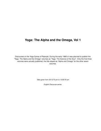
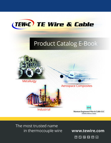
ANSI and IEC Color Codes†for Thermocouples, Wire and ConnectorsAll OMEGA Thermocouple Wire, Probes and Connectors are available with either ANSI or IEC Color Codes. In this Handbook,model numbers in the To Order tables reflect the ANSI Color-Coded Product. Please see the previous pages for instructions onhow to order IEC Color-Coded products.ConnectorsANSICodeConnectorsANSI MC 96.1Color CodingThermocoupleGradeAlloy CombinationExtensionGrade Lead– LeadJ – –IRONFe(magnetic)K – –CHROMEGANICKELCHROMIUMNi-CrT – –E – CHROMEGA NICKEL–N – –CONSTANTANCOPPERNICKELCu-Ni COPPERCuOMEGA-P NICROSILNi-Cr-SiRNONEESTABLISHED PLATINUM– 13% RHODIUMSNONEESTABLISHED PLATINUM– 10% RHODIUMUNONEESTABLISHED –BNONEESTABLISHEDPt-13% RhPt-10% RhCOPPERCuOxidizing or Inert.OMEGA-N u-NiAlternativeto Type K.More Stableat High TempsOxidizing or Inert.Do Not Insert in MetalTubes. Beware ofContamination.High TemperatureOxidizing or Inert.Do Not Insert in MetalTubes. Beware ofContamination.High TemperatureEMF (mV)IEC 584-3Over MaxColor CodingTemp Thermocouple IntrinsicallyRangeGradeSafe–8.095 to69.553–6.458 to54.886C*NONEESTABLISHED TUNGSTENTUNGSTEN– 5% RHENIUM 26% RHENIUMD*NONEESTABLISHEDTUNGSTENWW-5% ReTUNGSTEN26% RHENIUMW-26% ReW-26% Re TUNGSTENTUNGSTEN– 3% RHENIUM 25% RHENIUMW-3% ReW-25% Re–6.258 to20.872–9.835 to76.373–270 to 1300 C–450 to 2372 F–4.345to 47.513–50 to 1768 C–58 to 3214 F–0.226to 21.101–50 to 1768 C–58 to 3214 F–0.236to 18.693Extension GradeConnecting Wire forR & S Thermocouples,Also Known as RX & SXExtension Wire.Oxidizing or Inert.Do Not Insert in MetalTubes. Beware ofPLATINUMPlatinumContamination.30% RHODIUM 6% RHODIUMHighTemp. Common UsePt-30% RhPt-6% Rhin Glass Industry –(W3)Clean Oxidizing and Inert.Limited Use in Vacuumor Reducing. Wide–270 to 1372 CTemperature–454 to 2501 FRange, Most PopularCalibrationCONSTANTAN Limited Use in Vacuum or –270 to 1000 CReducing. Highest EMF –454 to 1832 FCOPPERChangeNICKELPer DegreeCu-NiNONEESTABLISHED(W5)–210 to 1200 C–346 to 2193 FReducing Vacuum orCONSTANTANInert. Good WhereCOPPER–270 to 400 CMoisture Is Present. LowNICKELTemperature & Cryogenic –454 to 752 FCu–NiApplicationsG*(W)Reducing, Vacuum,Inert. Limited Usein Oxidizing at HighTemperatures.Not Recommended forLow Temperatures.MaximumT/C GradeTempRangeMild Oxidizing,CHROMIUMNi-Cr – nmentBare WireVacuum, Inert, Hydrogen.Beware of Embrittlement.Not Practical Below399 C (750 F).Not for OxidizingAtmosphereVacuum, Inert, Hydrogen.Beware of Embrittlement.Not Practical Below399 C (750 F)Not for OxidizingAtmosphereVacuum, Inert, Hydrogen.Beware of Embrittlement.Not Practical Below399 C (750 F)–Not forOxidizing Atmosphere* Not official symbol or standard designationH-1 – –J – –K – –T – –E – –N – –R – –S – –U – –B0 to 1820 C32 to 3308 F0 to 13.8200 to 2320 C32 to 4208 F0 to 38.564NO STANDARDUSE ANSICOLOR CODE0 to 2320 C32 to 4208 F0 to 37.066NO STANDARDUSE ANSICOLOR CODE0 to 2320 C32 to 4208 F0 to 39.506NO STANDARDUSE ANSICOLOR CODE†IECCodeG(W)C(W5)D(W3)JIS color code also available. See page A-9 for details.H
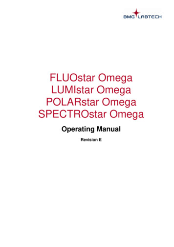
Thermocouple Tolerances(Reference Junction at 0 C)American Limits of Error ASTM E230-ANSI MC 96.1ANSI CodeStandard Limits†Special Limits†Temp RangeTolerance Value 0 to 750 C2.2 C or 0.75% 32 to 1382 F4.0 F or 0.75%0 to 750 C1.1 C or 0.4%32 to 1382 F2.0 F or 0.4%Temp RangeTolerance ValueTemp. Range*Tolerance Value 0 to 1250 C2.2 C or 0.75%-200 to 0 C2.2 C or 2.0% 32 to 2282 F4.0 F or 0.75%-328 to 32 F4.0 F or 2.0%0 to 1250 C1.1 C or 0.4%32 to 2282 F2.0 F or 0.4%Temp RangeTolerance ValueTemp. Range*Tolerance Value 0 to 350 C1.0 C or 0.75%-200 to 0 C1.0 C or 1.5% 32 to 662 F1.8 F or 0.75%-328 to 32 F1.8 F or 1.5%0 to 350 C0.5 C or 0.4%32 to 662 F1 F or 0.4%Temp RangeTolerance ValueTemp. Range*Tolerance Value 0 to 900 C1.7 C or 0.5%-200 to 0 C1.7 C or 1.0% 32 to 16523 F or 0.5%-328 to 32 F3 F or 1.0%0 to 900 C1.0 C or 0.4%32 to 1652 F1.8 F or 0.4%Temp RangeTolerance ValueTemp. Range*Tolerance Value 0 to 1300 C2.2 C or 0.75%-270 to 0 C2.2 C or 2.0% 32 to 2372 F4.0 F or 0.75%-454 to 32 F4.0 F or 2.0%0 to 1300 C1.1 C or 0.4%32 to 2372 F2.0 F or 0.4%Temp RangeTolerance Value0 to 1450 C1.5 C or 0.25%32 to 2642 F2.7 F or 0.25%0 to 1450 C0.6 C or 0.1%32 to 2642 F1 F or 0.1%Temp RangeTolerance Value800 to 1700 C0.5%1472 to 3092 F0.9 FNotEstablishedTemp RangeTolerance Value0 to 2320 C4.5 C or 1.0%32 to 4208 F0.9 FNotEstablished†* Not official symbol or standard designationWhichever value is greater.Note: Material is normally selected to meet tolerances above 0 C. If thermocouples are needed to meet tolerances below 0 C, the purchasershall state this as selection of material is usually required.IEC Tolerance Class EN 60584-2; JIS C 1602IEC CodeClass 1Class 2Class 3†-40 to 375 C 1.5 C375 to 750 C 0.4% Reading-40 to 333 C 2.5 C333 to 750 C 0.75% ReadingNotEstablishedJTemp RangeTolerance ValueTemp. RangeTolerance ValueKNTemp RangeTolerance ValueTemp. RangeTolerance Value-40 to 375 C 1.5 C375 to 1000 C 0.4%-40 to 333 C 2.5 C333 to 1200 C 0.75% Reading-167 to 40 C 2.5 C-200 to -167 C 1.5% ReadingTTemp RangeTolerance ValueTemp. RangeTolerance Value-40 to 125 C 0.5 C125 to 350 C 0.4% Reading-40 to 133 C 1 C133 to 350 C 0.75% Reading-67 to 40 C 1 C-200 to -67 C 1.5% ReadingETemp RangeTolerance ValueTemp. RangeTolerance Value-40 to 375 C 1.5 C375 to 800 C 0.4% Reading-40 to 333 C 2.5 C333 to 900 C 0.75% Reading-167 to 40 C 2.5 C-200 to -167 C 1.5% ReadingRSTemp RangeTolerance ValueTemp. RangeTolerance Value0 to 1100 C 1 C1100 to 1600 C [1 0.3% x (Rdg-1100)] C0 to 600 C 1.5 C600 to 1600 C 0.25% ReadingNotEstablishedTemp RangeTolerance ValueNotTemp. RangeEstablished600 to 1700 CTolerance Value 0.25% Reading600 to 800 C 4 C800 to 1700 C 0.5% ReadingMaterial is normally selected to meet tolerances above -40 C. If thermocouples are needed to meet limits of Class 3, as well as thoseof Class 1 or 2, the purchaser shall state this, as selection of material is usually required.†H-2
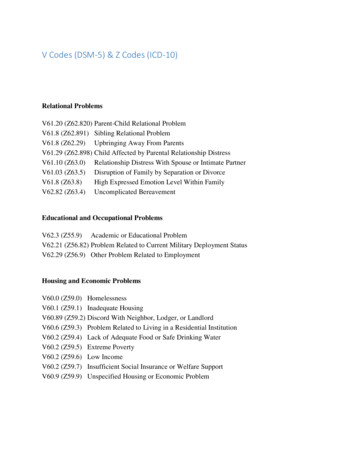
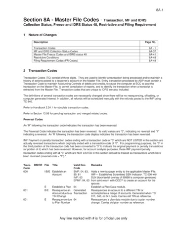
Wire Insulation IdentificationInsulationCodePP(Extension GradeEXPP)FF(Extension GradeEXFF)TT(Extension GradeEXTT)KKTGGG(Extension GradeEXGG)HHXRXCStandard BraidXL-Loose BraidXT-Tight BraidXSTFEInsulationAppearance ofThermocouple Grade lChloride(PVC)PolyvinylChloride(PVC)-40 to 105 C-40 to 221 FGoodExcellentGoodFEPorNeoflonFEPorNeoflon-200 to 200 C-338 to 392 7 to 260 C-450 to 500 FExcellentGoodExcellentKaptonKapton-267 to 316 C-450 to 600 FExcellentGoodGoodGlassBraidPFAorNeoflon-73 to 260 C-100 to 500 FGoodGoodExcellentGlassBraidGlassBraid-73 to 482 C-100 to 900 FPoorGoodPoor-73 to 871 C-100 to 1300 FPoorGoodPoorHigh Temp High TempGlassGlassBraidBraidGood toPoor to315 C (600 F) 315 C (600 F)RefrasilBraidRefrasilBraid-73 to 871 CPoor-100 to 1600 FNextelBraidNextelBraid-73 to 1204 C-100 to 2200 FPoorGoodPoorSilicaSilica-73 to 1038 C-100 to 1990 FPoorGoodPoorTFETFE-267 to 260 C-450 to 500 FExcellentGoodExcellentANSIcolorcodeshownH-3To orderIEC colorcode visitus onlineH
and Application GuideResistance To:AcidBaseFlameFairGoodGoodGoodGoodColor Coded PVC Extruded Over Each BareWire. PVC Applied Over Insulated Primaries.Affected by Ketones, tColor Coded PVC Extruded Over Each Bare Wire.PVC Applied Over Insulated Primaries. Affected byKetones, tColor Coded PFA Extruded Over Each Bare Wire. PFAJacket Extruded Over Insulated Primaries. SuperiorAbrasion and Moisture Resistance. Same BasicCharacteristics as FEP but Higher Temperature xcellentFair0.12 mm Glass Braid Over Each Conductor, and BinderImpregnated. Overall Glass Braid Applied andBindered. Binder Improves Moisture and AbrasionResistance but Is Destroyed Above 204 C (400 F)ExcellentExcellentExcellentExcellentFairHigh Temp. Glass Braid Over Each Conductor, andBinder Impregnated. Overall High Temp Glass BraidApplied and Bindered. Binder Improves Moisture andAbrasion Resistance but Is Destroyed Above 400 FExcellentPoorBraid of Vitreous Silica Fiber Applied to EachBare Wire, Then Over Both. Suitable to 982 C (1800 F)if Not Subjected to Flexure or AbrasionGoodExcellentGood toGood to315 C (600 F) 315 C (600 entExcellentExcellentExcellentANSIcolorcodeshownTo orderIEC colorcode visitus onlineH-4Fused Kapton Tape Approx. 0.15 mm Applied to Conductors. A0.10 mm Jacket Is Then Applied to Both. Excellent Moisture andAbrasion Resistance, High Dielectric Strength (7 kV/mil) RetainsMuch Physical Integrity After Gamma Radiation. FEP Is Used asAdhesive Binding Agent (Melts at approx. 260 C [500 F])PFA Extruded Over Each Bare Wire and a Glass Braidon the Jacket. May Be Used for Single Measurementto 343 C (650 F)High Temp, Alumina-Boria-Silica Ceramic Fiber BraidedOver Each Conductor Then Over Both. Not Recommendedfor Platinum Thermocouples or Exposure to Molten Tin andCopper, Hydrofluoric or Phosphoric Acids, or Strong AlkaliesSilica Is a Very High Purity, ChemicallyStable Yarn. (SiO2 Content 99%)Color Coded TFE Tape Applied to Conductorsand Jacket. Superior Abrasion, Moisture, andChemical Resistance.
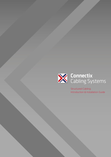
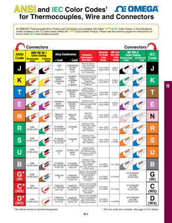
RK/PORTWARReference GuideU Properties of the sheath materialU Diameter and constructionof thermocouple assemblyThermocoupleWiresMetalSheathUpper Temperature Limit in C ( F) of ProtectedBare Wire Thermocouples Vs. Wire DiameterTemperature RangeT/COMEGACLAD is a three-part system composedof compacted MgO insulation, thermocouple wireand metal sheath. Four factors determine the useful servicetemperature for OMEGACLAD assemblies.U Range for the thermocouple wire (see table of error)U Maximum service temperature of insulation.In the case of MgO, this is in excess of 1650 C (3000 F)Sheath Material SpecificationsMaterial304 SS310 SS316 SS321 SSHastelloy XInconel*SUPER XLMagnesium Oxide InsulationMelting Continuous Tensile (PSI) StrengthPointMaximum@93 C@ 537 C( C/ F) Temp. ( C/ F) (200 F)(1000 F)1405/2560 900/165068,000 15,0001405/2560 1150/210075,000 27,5001370/2500 925/170075,000 23,0001400/2550 870/160070,000 17,0001260/2300 1200/220055,100 35,5001400/2550 1150/210039,000 5,0001400/2550 1204/220070,000 17,000Wire SizeType8 AWG 14 AWG 20 AWG 24 AWG 28 AWG 30 AWG 36 AWG0.128”0.064”0.032” (1100)320(600)PROBE TIPS CUTAWAY ARTGroundedCommon Thermocouple JunctionsExposedUngrounded* Oxidizing, Vacuum or Inert atmosphere onlyConductor Size 43536373839404142434445AWG American Wire GageSWG (British) StandardWire 8TwistedShielded 320.1220.1120.1020.0910.0810.071To convert from AWG to SWG: Determine wire diameter in inches (mm) from appropriate AWG.To convert 30 AWG to SWG, determine that 30 AWG is 0.0100”, which is equivalent to 33 SWGUpper Temperature Limit in C ( F) of OMEGACLAD Vs. Sheath Diameter0.020”0.5 mm0.032”0.8 mm0.040”1.0 mm0.062”1.6 mm0.093”2.4 mm0.125”3.2 mm0.188”4.8 mm0.250”6.3 mm260 (500)260 (500)260 (500)440 (825)480 (900)520 (970)620 (1150)720 (1300)&700 (1290)700 (1290)700 (1290)920 (1690)1000 (1830)1070 (1960)1150 (2100) 1150 (2100)300 (570)300 (570)300 (570)510 (950)580 (1075)650 (1200)730 (1350)820 (1510)260 (500)260 (500)260 (500)260 (500)260 (500)315 (600)370 (700)370 (700)SheathT/C Dia.BendsEasily!H-5H
Properties of PFA and FEP InsulationGeneral Properties of NeofIon, FEP and PFANeoflon/FEPNeoflon/PFAChemical Resistance: hydrocarbons, ethyleneglycol, battery acid, brake fluids, other chemicalsNO EFFECTNO EFFECTResistance to weatheringNO EFFECTNO EFFECTWater absorption (ASTM D570)Flammability (UL 83, Vertical Wire Flame Test)*The combination of chemicaland physical properties of FEP,PFA and Neoflon is a result ofits true fluorocarbon structure.This unusual structure leads toa material which has an almostuniversal chemical inertness;complete insolubility in all knownsolvents below 300 C(572 F); excellent thermal stability;and unsurpassed electricalproperties including low dielectricloss, low dielectric constant andhigh dielectric strength.Furthermore, FEP, PFA andNeoflon does not embrittle at verylow temperatures.0.1%0.1%NO AFTER BURNNO AFTER BURNMelting Point F518 F590 FMelting Point C270 C300 C200 C (392 F)177 C (350 F)PASS288 C (550 F)260 C (500 F)PASS2.152.15Neo
Title: thermocouple colour codes Author: omega Subject: iec ansi colour codes thermocouples wire connectors Created Date: 11/21/2007 1:56:58 PM