Transcription
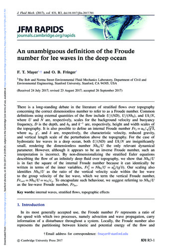
Froude forThoughtGETTING SEMI-PLANINGH U L L R E S I S TA N C E R I G H TThe semi-planing or semi-displacement hull is the bête noir of hull design. Getit right and higher speeds and efficiency are available; M/Y Silver (above) is agreat example. Differences of 30% are quite possible with all that means atplus and minus values. Trend to the plus percentage and you guzzle fuel as ifbuying it today at 1960s’ prices, go the other way and cost and environmentalimpact reduce radically. Demonstrable increased hull efficiencies are partof, for example, RINA’s green star notation. Here Dr Robert Ranzenbach ofDonald L. Blount & Associates, Inc. explains the process of optimisation usingthe results of public domain tank-testing results and offers design guidancefor those taking the semi-displacement or -planing route.the yacht report195
ISSUES & OPINIONS – SEMI PLANINGHISTORICALLY, MOST MEGAYACHT DESIGNS HAVEtended towards displacement or planingyachts. Appropriate hull forms and their attendantresistance characteristics for these operatingregimes are fairly well understood by navalarchitects. As the desirable size and speed haveincreased, many more megayachts are beingconstructed so that they now operate betweendisplacement and planing regimes, sometimesreferred to as semi-displacement or semi-planingdepending upon their specific speed and lengthcharacteristics.Recent examples of semi-displacement yachtsinclude Predator (below) and Silver, 73m LOAyachts with published maximum speeds of 28ktand 27kt respectively. Recent examples of semiplaning yachts include Lazy Me, 41m LOA with apublished maximum speed of 29kt, and Pure One(opposite), 46m LOA with a published maximumspeed of 32kt.The resistance characteristics of yachts operatingin these intermediate regimes are not as wellunderstood as displacement or planing yachts andoptimising performance of semi-displacement andsemi-planing yachts will require enhancementsto the design and analysis approach to ensurethe same level of confidence. Recently, CompanyPresident Donald L. Blount and naval architectJames McGrath published a study describing lowdrag/dynamically stable hull forms based uponanalysis of available public domain tow tank data.196the yacht reportHydrodynamic resistance of the bare hull of ayacht consists of the sum of two components:frictional and wave making.The information provided in that Royal Institute of Naval Architects(RINA) technical paper is valuable because it outlines the significantopportunities to reduce hydrodynamic resistance by carefully selectinghull forms applicable to each specific operating regime and offersspecific design guidance. Differences of greater than 30% betweenthe resistances of various hull forms are observed in this intermediateregime and naval architects can ill afford to be on the wrong side of theresistance curve given the present focus on fuel efficiency to reduceoperating costs and impact upon the environment.This experiment-based analytic approach is particularly useful inthe early design stage and is an important alternative method tothe many computational predictions methods that are available topredict resistance for displacement and planing yachts which arenot necessarily appropriate for this intermediate operating regime. Asummary of the technical approach, identification of key parametersinfluencing resistance, and design guidance for yachts operating inthe semi-displacement/semi-planing regime is provided here.BackgroundBefore describing some of the lessons learned from this analysis ofpublic domain tow tank data, a little technical background needs tobe given.Hydrodynamic resistance of the bare hull of a yacht consistsof the sum of two components: frictional and wave making.Frictional resistance characteristics are dependent upon waterline
ISSUES & OPINIONS – SEMI PLANINGlength, speed, and wetted surface area of the hull. Wave-makingcharacteristics are related to two non-dimensional similarityparameters, one called Froude Number that is a function of speed(V) and waterline length (L) and another parameter related to thepressure forces acting upon the hull bottom. When Froude number iscalculated based upon length, it is called the Length Froude number,FL V(gL)1/2, where g is the acceleration of gravity.Non-dimensional similarity parameters such as Froude number areuseful to compare physical phenomena at different yacht sizes andspeeds because when a non-dimensional similarity parameter isidentical the related physical phenomenon is also identical. Usingthis relationship, naval architects are able to obtain resistancecharacteristics when performing model-scale tests in towing tanks. Ifmodel-scale and full-scale Froude numbers are matched (by properlyadjusting the model-scale speed), then the tow tank results canbe extrapolated to the full-scale yacht because the wave-makingphenomena are identical.198the yacht reportIt is important to note that the relativecontribution of frictional and wave-makingresistance to the total bare hull resistancechanges as yacht speed varies. The relativecontribution of frictional resistance tends toreduce slightly as speed increases whereasthe wave making contribution tends to growslowly at first until “hull speed” is reached andthen grows quickly until one reaches “humpspeed”. Hump speed is the point associatedwith maximum growth rate of total resistance.As speed continues to increase, the relativecontribution of wave making begins to fall. Hullspeed is generally accepted to occur around aFL of about 0.4. Hump speed generally occursaround a FL of 0.5. Yachts should generally notbe designed to operate at a cruise or maximumspeed equivalent to this FL.Displacement yachts operate at relatively lowspeeds and the pressures acting upon the hullare largely the result of hydrostatic pressureassociated with the buoyancy force. Beyonddisplacement speeds, the influence of dynamicpressure associated with the high yacht speedacting upon the hull bottom grows and at planingspeeds largely dominates hydrostatic pressure.For semi-displacement and semi-planing yachts,both hydrostatic and hydrodynamic forces mustbe considered. It is this complicated pressurebalance that makes prediction of wave-makingresistance so challenging over this intermediateoperating regime.
ISSUES & OPINIONS – SEMI PLANINGTo put things into perspective, consider theFL associated with the maximum speed of theyachts mentioned earlier: Predator and Silverwhere FL is equal to approximately 0.6 and LazyMe (right) and Pure One where FL is equal toapproximately 0.9. This is in comparison to aplaning yacht such as Fortuna, a 41.5m LOAyacht with speed in excess of 65kt and a FL ofapproximately 1.9.Analysis and ResultsThe following parameters in decreasing level ofinfluence on resistance for a particular configurationof hull form over this FL range were identified:Other parameters such as block and prismatic coefficientcommonly identified as key parameters for traditional displacementhull forms.ΔFigure 1 shows a plot of bare hull resistance perunit weight (RBH/W) versus FL. The resistancecurves shown here are for specific yachts butare reflective of the general trends. It can beobserved for yachts operating below a FL of0.4 (displacement) that round bilge yachts offerless resistance when compared to single chineyachts. This trend continues until approximatelyFL equal to 1.0 which is generally consideredthe early stages of planing. It should be notedthat the boundary definition between what maybe called semi-displacement and semi-planing isnot generally agreed.Slenderness Ratio is the dominant factorLongitudinal centre of buoyancy/lengthLength-to-beam ratioΔPublically available results from towing tank testsof the following systematic series were collectedand analysed to identify the key influences onresistance over a FL range between 0.4 and 1.0:NPL (round bilge published in 1969 and 1976)DTMB Series 62 (single chine published in 1963),63 (round bilge published in 1963), and 64(round bilge published in 1965)NTUA (double chine published in 1999 and2001)USCG (single chine published in 2006)Delft Series (single chine published in 1982similar to DTMB Series 62)Only Slenderness Ratio, defined as the length (L) divided by thecube root of the volume of displaced water ( )equal to L/ 1/3, willbe discussed here. For a more detailed discussion about the otherparameters, please consult the original RINA technical paper.Figure 2 shows a plot of RBH/W versus Slenderness Ratio. Theresults are plotted for three different types of hull form (round bilge,single chine, and double chine) at three Length Froude numbers,0.4 (displacement), 0.6 (semi-displacement) and 0.9 (semiplaning). The trend lines for each hull form type are based uponthe average of collected data for a variety of yachts.For semi-displacement yachts, it can be observed that bare hullresistance per unit weight generally decreases relatively significantlyas slenderness ratio increases but the trend tends to wane asslenderness ratio increases above 7.5 with a minimum valueoccurring for round bilge hulls at a slenderness ratio of approximately9.5. It can also be observed that the round bilge hull form offers theleast resistance while the single chine generates the most resistancewith double chine in between. This trend is consistent across therange of slenderness ratios shown top of page 202.
ISSUES & OPINIONS – SEMI PLANINGRound bilge yachts tend to be moresusceptible to this form of instabilitythan single or double chine hullsFor semi-planing yachts, similar trends for single chine and round bilgeyachts can be observed but the rate of bare hull-resistance reduction asslenderness ratio increases is lessened. Interestingly, the limited amountof available data for double chine hull suggests that the influence ofslenderness ratio is quite muted and at a slenderness ratio of around 6.0to 6.5, a double-chine hull form may offer the least resistance.The results show that the bare hull resistance of semi-displacementand semi-planing yachts are strongly dependent upon SlendernessRatio. For a fixed length, this translates into a strong dependence uponweight unlike for displacement yachts whose FL is less than 0.4. Theslenderness ratio dependency is most significant for yachts operatingnear a FL of 0.6.Design GuidanceBased upon the analysis of the data described herein and DLBA’sdesign experience, the following design guidance for semidisplacement and semi-planing yachts is provided:Yachts should have purely round bilge hull forms up to a FL ofapproximately 0.4Bulbous bows are an important element to reduce resistance up to aFL of approximately 0.6Yachts should have round bilge hull forms with longitudinal flowseparators/chines/knuckles beginning at the stem above the staticwaterline, continuing aft to at least amidships below the waterline for FLbetween 0.4 and 0.9Double chine hull forms appear to be desirable when operating at a FLgreater than approximately 0.8Single chine hull forms appear most desirable when mostly operatingat a FL greater than approximately 1.0202It is important to note that in the quest for lowresistance one must not forget to addressdynamic instability issues related to speedinduced bow diving, heel and/or uncontrolledcourse keeping (yaw) changes which are nonoscillatory. These instabilities result when a heavilyloaded yacht operates at speeds in excess ofapproximately 25kt and the velocity of water atthe surface of the hull generates low (suction)pressures. Should these dynamic pressures occurasymmetrically, as might happen in a seaway, oneside of the yacht may be sucked down (resultingin a heel angle) and remain in that attitudeuntil speed is reduced. The heeled attitude willlikely induce a yaw moment resulting in coursedeviation/bow steering.Round bilge yachts tend to be more susceptibleto this form of instability than single or doublechine hulls, although the latter two may alsoexhibit this characteristic at high speed whenoverloaded and/or operated with a low trimby the bow. Whenever a round bilge yacht ispowered so that it may operate at speeds greaterthan FL 0.75 or chine hulls have operationalconditions such that the ratio of LongitudinalCentre of Gravity (LCG) divided by the Length(L) approaches 45% Forward of the Transom(FOT) or greater, then it is recommended thatmodel experiments be conducted to evaluate thepotential for dynamic instabilities.ConclusionAppendix B of the RINA technical paper provides a table of minimumRBH/W for round bilge, double chine, and single chine hull forms for FLfrom 0.4 to 1.0 as a function of slenderness ratio. This table providesa benchmark by which naval architects may evaluate the relative barehull resistance of new hull designs.Growing numbers of megayacht designs arebeing constructed as semi-displacement orsemi-planing yachts. The analysis of publicdomain tow tank data has identified thedominant influence of hull form and slendernessratio over this intermediate operating regime. Itis hoped that this information will assist navalarchitects in the early design stages by providingoptimal minimum resistance targets.Dr Robert RanzenbachDonald L. Blount & Associates, IncYacht images courtesy of: Baglietto, Feadship,www.puremarinegroup.com and Justin RatcliffeFortunately, many aspects of these design guidance elements do notdegrade the seakeeping qualities of the high-performance yachts.To comment on this article, email issue107@synfo.com with subject: Froude for Thoughtthe yacht report
Froude for Thought GETTING SEMI-PLANING HULL RESISTANCE RIGHT The semi-planing or semi-displacement hull is the bête noir of hull design. Get it right and higher speeds and effi ciency are available; M/Y Silver (above) is a great example. Differences of 30% are quite possible with all that means at plus and minus values.