Transcription
RP562THE THERMAL EXPANSION OF REFRACTORIES TO1,800 C.By R.A. HeindlABSTRACTThe linear thermal expansions of the following 36 materials were measured:African chrome sand; Cuban, Grecian, Friable African, Rhodesian Imperial,Indian and Turkish chrome ores; Austrian, Calif ornian, and electrically fusedmagnesites; a periclase brick; a spinel brick; two types of fire-clay bricks and twoof fire clays; Kentucky, Tennessee, and English ball clays; Georgia kaolin andand English china clay; an 80 percent alumina brick; artificial corundum, diaspore, bauxite; five mullites, each of which was prepared from different rawmaterials; two zircon bricks and afurnaced zirconium silicate; silicon carbide,Data are also given on artificial graphitea silica brick, and an insulating brick.which had been preheated several times to 1,800 C. Measurements were madebelow 1,000 C. in both an oxidizing and a reducing atmosphere. Above, 1,000 When the refractoriC. the materials were tested in a reducing atmosphere only.Petrographicness of the materials permitted they were tested up to 1,800 C.analyses of the materials were made before and after the several heat treatments.CONTENTSPageI.II.III. 15 loIntroductionMaterials and specimensApparatus1.2.'.DescriptionCalibration JJjJJ181IV. Method of testingV. Results1. Linear thermal expansion2. Petrographic analysesVI. SummaryI.J,* y'j\ **i6bINTRODUCTIONof refractoryfor information relative to the expansionthey arewhichinrangetemperaturethebeyondmaterials, up to anddealingreportsofnumbernow used, is evidenced by an increasing2value of suchtheregardingreasonsgaveNortonwith the subject.vol. 8. na 12 ppExpansion of Refractories J .Am. Cer SociF.The needH.Norton, The ThermalK. Becker, X-ray Method of Determining Coefficient**" &?!?&«, and H.ofl. rnjsih,J \ *-Expansion at High Temperatures,Immke, The ImportanceofThermal Expansionin theValuation ofRefractory Material, Tonin. Ztg., vol. 51 (26), pp. 417-422, fvol.lomn Ztg.,Temperatures, Tonin.high TemperaturesgHans Hirsch and Max Pulfrich, Expansion Measurements at1,600 52 (36), pp. 712-713, 1928.toMaterialsRefractoryyeirm,iuof«.„# *.FxnansionThermalyk x Pa"sion 01K. Endell and W. Steger, The Measurement of thevoL 5 m, PP. 3 , !»-«C, Archiv. Eisenhuttenives, vol. 1 (11), 1928; FeuwfestKjramos, v20 to 1,400 CWilli M.Cohn, Expansion Measurements fromMaterials in theaE a 10R JLH. Reich, A New Apparatus for Measuring the Thermal ;P.1932.oio 13 (4), PPj 157-166.vol.Oesell.,1925Temperature Range 0 to 1,700 C, Benchte Deut. Ker.jm y,:2F H.Norton, The Thermal Expansionof Refractories,J.Am. Cer. boc,voi. », no.vi,715mQ
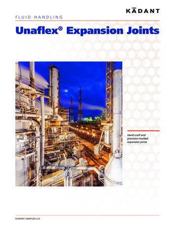
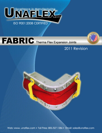
Bureau of Standards Journal of Research716[Vol.wIt may also be pointed out that it is not at all unusualfor refractories to be used at temperatures considerably higher thanthose at which they had been heated during the manufacturing process.information.In such cases physical and chemical changes not completed daringIn many cases thethe manufacturing stage continue to progress.linear thermal expansion is affected by such additional heating whichin turn may greatly affect the stresses set up in the refractory duringuse.The present report deals not only with the expansion of the wellknown types of refractory materials to temperatures sufficiently highto cause many of them to soften or deform but also with the effecton the expansion when the materials are heated to a higher temperature than that at which theyfirst test.II.had been heated preliminaryto theMATERIALS AND SPECIMENSSeven chrome ores, four magnesites, five mullites, two fire-claytwo fire clays, three ball clays, two kaolins, three zircons, andone each of spinel, silicon carbide, artificial corundum, diaspore,bauxite, 80 percent alumina fire brick, silica brick, and insulatingA large proportion ofbrick were included in this investigation.3and the othersthese materials were furnished by manufacturerswere available in the bureau laboratories.Test specimens approximately 5% inches long and % inch squarewere cut from commercial bricks if available, but if bricks were notavailable specimens of similar dimensions were prepared from rawmaterials which had been ground to pass a 40-mesh sieve.Thespecimens were prepared by adding sufficient water or gum tragacanth to each ground material so it could be readily molded. Afterremoving the damp specimens from the mold they were dried, heated,and cut to the required dimensions. The specimens cut from the brickswere tested without further treatment whereas most of those preparedfrom the raw material were tested after having been heated at 1,400 C. for 5 hours and cooled with the furnace in about 36 hours.bricks,III.1.APPARATUSDESCRIPTIONA furnace of the high frequency induction type shown in figure 1was used for determining the expansion of the various materials upto 1,800 C.The heat is generated through the medium of a cylindrical graphite muffle 12 inches long, 6 inches in diameter, and havinga wall ', inch thick.The gradual oxidation of the graphite mufflewas the cause of a reducing atmosphere within the furnace. Theconverter for controlling the power input to the furnace is shown onthe right in the figure.An Ames micrometer dial graduated in tenthousandth inch was supported independently of the furnace by aframework, the legs of which were fused quartz tubes.The Bet-up of the specimen is indicated by the sketch in figure 2.rhifl Bet-up formed a continuous system which also could expand andcontract independently of the furnace.Tungsten plates % inchu'J Tll? Shm Co - P adelphia Pa.; Harbison-Walker Refractories Co., Pittsburgh, Pa.; NortonASSp Q "»? F ";e Brick Co., Mexico, Mo.; Champion Spark Plug Co., Detroit.W!nItanium Alloy1n,?,-fManufacturingCo., NiagaraFalls,N.V.; Babcock&Wilcox Co.,New York, N.Y.
Heindl]Expansion of Refractoriesto 1,800 0.717DialFused Quartz-;\GraphiteGraphite tubefor optical pyrometer sightingTungsten platesSpecimenGraphite Graphite PorcelainThermocoupleFigure .-ShowingTheube4the specimen, specimen support, andthe expansion to the micrometer diat.fused quartz rod does not extend into the furnace.the system transmitting
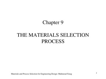
—Bureau of Standards Journal of Research718[Vol. 10square and 0.015 inch thick were placed between the test specimenand the graphite pieces. The specimen was placed within a muffle,inside diameter 2% inches, prepared from zirconium silicate. Theweight of the pieces resting on top of a specimen and making contactwith the dial was 4 ounces.Two platinum to platinum-rhodium thermocouples were placedalongside the specimen, one approximately three fourths inch belowthe top end and the other the same distance above the bottom end.These couples could be readily removed during a test through thelower end of the furnace without disturbing the set-up. The opticalpyrometer shown in figure 1 was fixed in position, preceding the test,so that it sighted on the bottom of the closed end graphite tube indicated in figure 2. This tube was placed near the middle of the specimen and as close to it as possible without actually touching it.IZOO(000DEGREESFigure3.Calibration curveinches long were testedC forthe7apparatus when samples approximately 6 /&and curves2.1400C.AandBinvolved initsderivation.CALIBRATIONThe movements indicated by the micrometer dial during an expansion test represented the difference between the total expansion ofthe built-up column composed of the various parts shown in figure 2and the vertical expansion of the outer framework and dial supportshown in figure 1. The first step in the calibration was to makeseveral tests with a bar of artificial graphite, 5.737 inches long and1 inch in diameter, as the specimen.In each of these tests the temperatures were increased to a maximum of 1,800 C. at the same rateand (he dial readings were recorded in the same manner as in the latertests.After preliminary heatings the dial readings for like temperatures m different tests were nearly the same and when plotted werefound to lie along the smooth curvein figure 3.This establishedthe fact that the expansions of the entire measuring system werepractically the same in repeated tests with the same specimen andBet-up.During the course of the investigation several additionaltesta were made with the graphite bar as the specimen and in these,the readings, beginning at approximately 250 C. did not deviatemore than 2.0 percent from curve A, figure 3.A
Expansion of RefractoriesHeindt]toRepeated readings over a temperaturewere then made with a bar (5.852 inchesthermal expansion of which was known.increase of temperature was the same as in1,800 C.719range of 20 to 1,000 C.long) of fused quartz, theIn these tests the rate ofother tests. Dial readingsin the different tests of fused quartz checked, which confirmed theindications of the previous tests that the effects of expansions of supports for the specimen and the dial did not vary significantly.Deducting the expansion of the fused quartz bar from these dialreadings gave the corrections which should be deducted from dialreadings in later tests to obtain the expansion of specimens investiThese corrections are shown by solid portion of curve C,gated.figure 3.Appying these corrections to the readings obtained withthe graphite bar (curve A) gave the values for the expansion of thebar itself below 1,000 C. which are shown by the solid portion ofcurve B, figure 3. 4Curveshowed no irregularities between 1,000 and 1,800 C;consequently it is logical to assume that neither curvenor C above1,000 C. should show irregularities.Moreover, as the curvature ofcurvein the temperature range 500 to 1,800 C. and also that ofin the range 500 to 1,000 C. were approximately constant, itcurveseemed reasonable to assume that the curvature of curve B wouldremain approximately constant from 500 to 1,800 C. Accordinglycurvewas extended from 1,000 to 1,800 C. based on that assumption.The calibration or correction curvewas then extrapolatedto 1,800 C. by taking the difference between curvesand B at100 C. intervals in the range 1,000 to 1,800 C.further precaution was taken in that the furnace was calibratedto 1,000 (3. with the specimen of fused quartz preceding practicallyevery test of a material.ABABBCAAIV.METHOD OF TESTINGLinear thermal expansion measurements were made of the samespecimen, of each of the materials, in steps as follows: (1) Up to1,000 C. at approximately 100 C. intervals, using either the entirespecimen and the apparatus described in the Second Progress Reportof the Sagger Investigation 5 or chips of the specimen and the interferometer. 6(2) In the induction furnace to some temperature above1,000 C, but in no case above 1,800 C.(3) The procedure describedunder (1) was repeated with the specimen taken from the inductionfurnace.(4) After the measurements described under (3) were completed, the specimen was again tested in the induction furnace at thehigher temperatures.There were two reasons for this procedure, (a)the time for making the tests in the induction furnace could be considerably lessened because only a few observations below 1,000 C.would be necessary, and (6) an error in the set-up of the specimen inthe induction furnace would be quickly detected because the dataobtained below 1,000 C. with the induction furnace should generally4The values obtained checked the expansion of the graphite bar determined over the range 20 to .500 C.by means of an apparatus described elsewhere. R. F. Geller and R. A. Heindl, II. Progress Report onInvestigation of Sagger Clays— Some Observations as to the Significance of Their Thermal Expansions,J.Am.Cer.Soc, vol. 9, no. 9, pp. 555-575, 1926.4See footnote 4.,„XT„6 C.Q. Peters and C. H. Cragoe, B.S.Sci. Paper No. 393, and O. E. Mcrritt, B.S.Sci. Paper No. 485.The specimens from which the chips were cut did not always receive the corrseponding heat treatmentto 1,000 C.173145—332
Bureau720of Standards Journal of Research[Vol.wagree with those previously obtained in the furnaces operating onlyto 1,000 C.Temperatures in the induction furnace were measured with thethermocouples up to approximately 1,500 C, following which thecouples were removed and the temperatures observed with an opticalpyrometer. In testing with the induction furnace, temperaturereadings to and including 1,000 C. were taken at approximately250 C. intervals, thereafter at approximately 100 C. intervals.It was always the practice to check the optical pyrometer against thethermocouples before their removal. Temperatures were maintainedfor approximately 15 minutes before the final micrometer dial readingswere recorded for each temperature up to 1,500 C; thereafter noHowever, aneffort was made to stop at any specific temperature.attempt was made to regulate the power input so that readings weretaken only while the furnace temperature was increasing at a comparatively slow rate or not at all.The maximum temperature at which expansion or contractionmovements were observed depended on the refractoriness of thematerial, but in no case did it exceed 1,800 C.In most instances observations at temperatures above 1,000 C.were made of each specimen twice, namely, (1) after its preparation,and (2) after its initial test in the induction furnace. This procedureafforded the means of determining whether any changes had occurredin the expansions of the materials as a result of having been heatedin the induction furnace at temperatures considerably higher thanthose at which they had been initially heated.V.1.RESULTSLINEAR THERMAL EXPANSIONLinear thermal expansion or contraction values for all the materialsare shown in the curves given in figures 4 to 9, inclusive.Observations (filled in circles) with the induction furnace below 1,000 C.are not given in figures 5 to 9 because they very nearly coincided withthe observations (clear circles) obtained in the furnaces operated onlyto 1,000 C.Pertinent data are summarized in table 1detailed discussion ofthe data, therefore, i
RP562. THETHERMALEXPANSIONOFREFRACTORIESTO. 1,800 C. ByR.A.Heindl. ABSTRACT sweremeasured: desianImperial, delectricallyfused File Size: 1MBPage Count: 22