Transcription
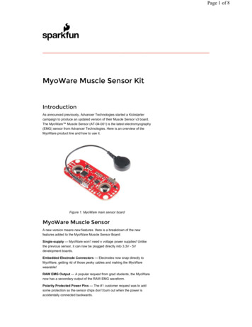
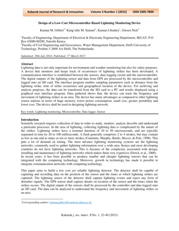
QS Sensor ModuleQSMSensor Interfaces369242k 1 12.22.15QS Sensor ModuleThe QS Sensor Module (QSM) is a ceiling-mounteddevice that integrates LutronR wireless and wired sensorsand controls through the QS communication link toEnergi Savr NodeTM (ESN) units, GRAFIK EyeR QScontrol units, QuantumR systems, SivoiaR QSshades / draperies, and myRoomT control modules.Features Uses Clear ConnectR RF Technology for communicationwith Radio Powr SavrTM occupancy sensors, RadioPowr SavrT daylight sensors, and PicoR wirelesscontrollers. QSM connects to four LutronR wired sensors orcontrols—occupancy sensors, daylight sensors,EcoSystemR infrared (IR) receivers, or EcoSystemRwallstations. Does not apply to wireless only models. Powered by the QS link—no line voltage connections arerequired. Contact Lutron for compatibility details with theQuantumR system. Compatible with the entire ESN product family:— Allows LutronR wired occupancy sensors, daylightsensors, EcoSystemR wall stations, EcoSystemRIR receivers, PicoR wireless controllers, Radio PowrSavrT wireless occupancy sensors and daylightsensors to control ESN units. Compatible with GRAFIK EyeR QS control units.— GRAFIK EyeR QS control unit models startingwith QSGR.System ExampleEcoSystemRDigital Links(up to 64 ballasts each)WiredDaylightSensors(up to 4) 1,2— Allows LutronR wired or Radio Powr SavrT wirelessoccupancy sensors and daylight sensors linked to aQSM to control the GRAFIK EyeR QS control unit.— Contact Lutron for compatibility with PicoR wirelesscontrollers, EcoSystemR wallstations, and EcoSystemRinfrared (IR) receivers. Compatible with SivoiaR QS shades / draperies.— Allows PicoR wireless controllers to control SivoiaR QSshades / draperies (QSM models with wireless inputsonly). Compatible with myRoomT power modules.— Allows Lutron wired & wireless occupancy sensors tocontrol power modules.— Allows PicoR wireless controls to control powermodules.WiredOccupancySensors(up to 4) 1Wired EcoSystemRWallstationor IR receivers(up to 4) 1NORTULORControl Power120-277 V WirelessCommunicationQS linkseeTouchR QS eContactClosureInput Job Name:Job Number:Radio Powr SavrTMOccupancy Sensor(up to 10 per QSM)Pico WirelessController (up to10 per QSM)QSMWired OccupancySensors (up to 4)Wired EcoSystemRWallstation orIR receivers(up to 4)IR TransmitterNORTULWired DaylightSensors (up to 4) 2ORRadio Powr SavrTDaylight Sensor(up to 10 per QSM)IR TransmitterORS p e c i f i c at i o n S u b m i t ta lModel Numbers:ORNotes:1 Up to 4 wired inputs total (of any type).2 Up to 16 wired daylight sensors totalper EcoSystemR link.Apple, iPhone, and iPod touch are trademarks ofApple Inc., registered in the U.S. and other countries.Page1
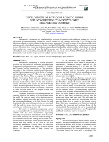
QS Sensor ModuleQSMSensor Interfaces369242k 2 12.22.15ModelsFrequency / Channel Code*Number of Wired InputsMounting MethodQSMX-XW-XFrequency / Channel Code*2—431.5 - 436.6 MHzU.S.A., Canada and Mexico3—868.1 - 869.8 MHzEuropean Union and United Arab Emirates4—868.1 - 868.5 MHzSingapore and China5—865.5 - 866.5 MHzIndia7—433.0 - 434.7 MHzHong KongX—No RF* Contact Lutron for frequency / channel code compatibility withyour particular geographic region if it is not indicated above.Number of Wired Inputs4—4X—NoneMounting MethodC—Ceiling MountJ—Junction Box Ceiling MountAvailability/CompatibilityRefer to the chart below to determine QSM model availability andcompatibility with different sensor models.LutronR Radio Powr 2-XW-JOccupancy / Vacancy SensorsDaylightSensors *LRF2-OCRB-P, LRF2-OHLB-P,LRF2-DCRBLRF2-OKLB-P, LRF2-OWLB-P,LRF2-VHLB-P, LRF2-VKLB-P,LRF2-VWLB-P, LRF2-OCR2B-WH,LRF2-VCR2B-WHLutronR PicoRWireless ControllersMRF2-3BRL, MRF2-3B,MRF2-2BRL, B-Gxx-xxxPJ-3BRL-Gx-xxxQSM3-4W-C LRF3-OCRB-PQSM3-XW-CLRF3-DCRBQSRKP-2, QSRKP-2R,QSRKP-3RQSM4-4W-C LRF4-OCRB-PQSM4-XW-CLRF4-DCRBQSRMP-2, QSRMP-2R,QSRMP-3RQSM5-XW-CLRF5-DCRBQSRNP-2, QSRNP-2R,QSRNP-3, QSRNP-3RQSM7-4W-C LRF7-OCR2B-PQSM7-XW-CLRF7-DCRBQSRQP-2, QSRQP-2RQSRQP-3, QSRQP-3RQSMX-4W-CN/AN/ALRF5-OCRB-PN/A* Daylight sensors can't be used as part of myRoomT solutions. Job Name:Job Number:S p e c i f i c at i o n S u b m i t ta lModel Numbers:Page2
QS Sensor ModuleQSMSensor Interfaces369242k 3 12.22.15SpecificationsQS Sensor Module (QSM) Power24–36 VCurrent draw:max 400 mA (models with wired input)max 100 mA (models without wired input)Power Draw Units: (PDU)Refer to the QS Link Power Draw Units specificationsubmittal (LutronR P/N 369405) for information concerningPDUs on the QS Link. Use only LutronR approved powersources.10-year power failure memory: restores settings andprogramming after power interruption.RegulatoryLutronR Quality Systems registered to ISO 9001.2008.QSM2 – cUL US Listed (USA and Canada). FCC Compliant. Complies with the limits for a Class Bdigital device, persuant to Part 15 of the FCC Rules (USA). IC Certified. (Canada). SCT Certified (Mexico).QSM3 – CE Marked (European Union). TRA Type Approved (United Arab Emirates).QSM5 – WPC Type Approved (India). QSM7 –FCC Compliant. Complies with the limits for a Class Bdigital device, pursuant to Part 15 of the FCC Rules (USA).EnvironmentAmbient Temperature Operating Range: 32 ºF to 104 ºF(0 ºC to 40 ºC).Relative humidity: less than 90% non-condensing.For indoor use only.TerminalsInput wiring: 22 AWG to 12 AWG (0.5 mm2 to 4.0 mm2)QS link wiring: 22 AWG to 12 AWG (0.5 mm2 to 4.0 mm2)MountingQSM units should be mounted in the middle of nonmetal ceiling tile or drywall, visible from inside the space.Installation near metal other than a Junction Box mayreduce RF range. Job Name:Job Number:S p e c i f i c at i o n S u b m i t ta lModel Numbers: Wireless Communication(models with wireless inputs only)RF Range: 60 ft (18 m) line of sight, or 30 ft (9 m)through typical construction materials. To ensure optimal wireless range, install the QSM inthe ceiling in a visible position from inside the space.LutronR Radio Powr SavrTM Occupancy sensor(up to 10)LutronR Radio Powr SavrT daylight sensor (up to 10)LutronR PicoR wireless controllers (up to 10)Wired Inputs There are 4 universal wired inputs. Each input canaccept one of the following:- LutronR EcoSystemR wallstations- LutronR occupancy sensors (LOS- series)- LutronR daylight sensors (EC-DIR- series)- LutronR EcoSystemR infrared (IR) receivers (EC-IR,EC-DIR- series)- LutronR Wired PicoR Controls Use of both the infrared receiver and daylight sensoron the EC-DIR- series sensors is considered twowired inputs on a QSM Maximum wiring distance 150 ft (46 m) Only wired (LOS- series) and wireless occupancysensors may be used in myRoomT; no EcosystemRwallstations, daylight sensors, EcosystemR IRreceivers or wired PicoR controlsQS Link Limits The QS link can have up to 100 devices. Each QSM counts as 1 device towards the100 device limit. Each QSM draws 3 Power Draw Units (PDUs) onthe QS link. Wired sensors add to the PDU draw of a QSM.Refer to the QS Link Power Draw Units specificationsubmittal (LutronR P/N 369405) for informationconcerning PDUs. QS link maximum wire run length is 2000 ft (610 m). See the commercial system rules spec (P/N 369821)for system specific limitations.Page3
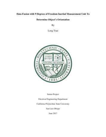
QS Sensor ModuleQSMSensor Interfaces369242k 4 12.22.15Mechanical Dimensions (All Models)Side ViewFront ViewBack View(QSM2-4W-C shown)4.04 in(103 mm)1.17 in(30 mm)Mounted (-C Models)CeilingMounted (-J Models)CeilingCeiling thickness range for -C modelsMin 0.30 in (8 mm)toMax 1.20 in (30 mm)CeilingCeilingUse appropriate Mud Ring for ceiling tile thicknessUse Mud Ring with holespacing shown below.(Mud Ring not included withany QSM models)2.75 in (70 mm) Job Name:Job Number:S p e c i f i c at i o n S u b m i t ta lModel Numbers:Page4
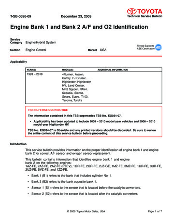
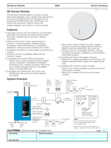
QS Sensor ModuleQSMSensor Interfaces369242k 5 12.22.15Wiring: QS Link and Wired Inputs1CommonV MUXMUXRed 20 – 20 VCOM – CommonBlackBlue or GrayS4 – SignalWhiteCOM – Common 20 – 20 VRedQSLinkS3 – SignalRed 20 – 20 V(QSM2-4W-C shown)COM – CommonS2 – SignalWhite 20 – 20 VRedEcoSystemRinfrared (IR) receiverBlackS1 – SignalCOM – CommonBack View22 AWG to 14 AWG(0.5 mm2 to 2.0 mm2)Lutron CableStandard: C-CBL-522S-WH-1Plenum: C-PCBL-522S-CLMax. Wired Input wirelength 150 ft (46 m)per inputInput 21,2Occupancy sensorBlackInput 11,2,3YellowBlackDaylight sensorInput 31,222 AWG to 14 AWG(0.5 mm2 to 2.0 mm2)Lutron CableStandard: C-CBL-522S-WH-1Plenum: C-PCBL-522S-CLMax. Wired Input wirelength 150 ft (46 m)per inputInput 41,2EcoSystemRwallstation orPicoR Wired Controls22 AWG to 14 AWG(0.5 mm2 to 2.0 mm2)Max. QS link wirelength 2000 ft (610 m)1 Only on QSM models with wired inputs.2 Note: For reference only. Each input is universal and can accept any of the inputs shown above.3 Only daylight sensor signal connected to QSM shown above. Use of IR signal counts as anadditional input on the QSM. Job Name:Job Number:S p e c i f i c at i o n S u b m i t ta lModel Numbers:Page5
QS Sensor ModuleQSMSensor Interfaces369242k 6 12.22.15Wiring: Device PowerSingle QSM powered by an ESN unitESN unitESN unitQSMCOMV MUXMUXCOMV MUXMUXQSMMultiple QSMs powered by an ESN unit and a QS Link Power SupplyNote: A QS Link Power Supply may be necessary if PDUs required by QSMs exceed available PDUs from thedevice supplying power.ESN unitThe ESN unit powers QSMA; no terminal 2 connectionbetween QSM A and QSLink Power SupplyThe QS Link Power Supplypowers QSM B and C;QS LinkPower SupplyQSM BCOMV MUXMUXQSM AMUXMUXCOMCOMV MUXMUXQSM CMUX and occupyterminals 2 and 3 on theQS Link Power Supply. Job Name:Job Number:S p e c i f i c at i o n S u b m i t ta lModel Numbers:Page6
Contact Lutron for compatibility details with the QuantumR system. Compatible with the entire ESN product family: — Allows LutronR wired occupancy sensors, daylight sensors, EcoSystem R wall stations, EcoSystem R IR receivers, PicoR wireless controllers, Radio Powr SavrT wireless occupancy sensors and daylight sensors to control ESN .