Transcription
SEISMIC CODE EVALUATIONDOMINICAN REPUBLICEvaluation conducted by Jorge GutiérrezNAME OF DOCUMENT: “Recomendaciones Provisionales para el AnálisisSísmico de Estructuras” (“Provisional Recommendations for the Seismic Analysisof Structures”). Norm M-001YEAR: Approved in December of 1979. Reprinted in October 2001.GENERAL REMARKS: Drafted by SODOSISMICA (Dominican Society ofSeismology and Seismic Engineering) and Approved by the “Departamento deNormas, Reglamentos y Sistemas” (DNRS) (“Department of Norms, Regulationsand Systems”) of the “Secretaría de Estado de Obras Públicas yComunicaciones” (SEOPC) (“Secretary of Public Works and Communications”).At present time work for a new Seismic Code together with a GeneralConstruction Code (“Código General de Construcciones”) is in a very advancedstage. The draft has been finished and SEOPC has requested a final review fromSOSOSISMICA. It is expected that it will be ready for publication sometime thisyear (from Hector O’Reilly, President of SODOSISMICA, personal e-mailcommunication).SPECIFIC ITEMS:NOTE: Bracketed numbers refer to Code specific chapters or articles: [Parentheses numbers refer to Items of this document: (see 2.2)]1. SCOPE1.1Explicit concepts. [1.2]The Code is intended for buildings and similar structures only.As its name indicates, the Code refers specifically to the seismic analysisof buildings; for the design of structural elements and components theCode refers to USA or European Norms (ACI, AISC, CEB) or othernational Norms from DNRS/SEOPC.
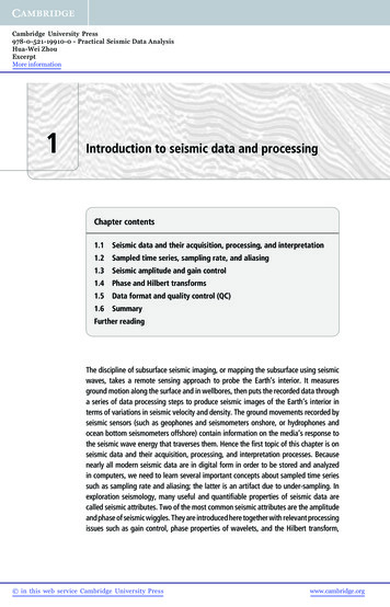
1.2Performance Objectives.Not explicitly considered.2. SEISMIC ZONING AND SITE CHARACTERIZATION2.1Seismic Zoning (Quality of Data). [3]The country is divided in two seismic zones, Zone I High Seismicity andZone II Medium Seismicity according to the following figure:Being a 1979 Code, it would be expected that the data considered isalready outdated.2.2Levels of Seismic Intensity. [6.4.4]A Seismic Zone Coefficient Z, affecting the Seismic Coefficient Cb (see4.2) is assigned to each Zone:Seismic ZoneIIIZ12/32
2.3Near Fault considerations.Not considered.2.4Site Requirements.Not mentioned.2.5Site Classification. [6.4.6]Four types of sites related to the soil conditions are defined, whosecorresponding S coefficients that affect the Seismic Coefficient Cb (see4.2) are given by the following Table.Soil Type12342.6PropertiesRock or rock derived firm soilsSoils from sedimentary marine depositsRecent alluvial soil depositsUndefined soilsS1.001.201.501.35Peak Ground Accelerations (Horizontal and Vertical).No peak ground accelerations are given in the Code. However, theplateau for the Elastic Response Spectra (see 4.1) is given as 0.635 for alltypes of soils on Seismic Zone I. Therefore, an effective horizontal peakground acceleration, estimated as 40% of the plateau, could be estimatedas 0.25g. For Zone II it would be 2/3 of this value (see 2.2) or 0.17g.3. PARAMETERS FOR STRUCTURAL CLASSIFICATION3.1Occupancy and Importance. [4; 6.4.5]Four groups A, B, C and D are defined and a Use Factor U definedaccording to the following Table:GroupDescriptionABCEssential, hazardous or high occupancy buildingsOrdinary buildingsBuildings not included in Groups A or B whosecollapse will not cause loss of life or affect otherbuildings.Buildings that can not be classified as Group A, B orC. In these cases the DNRS/SEOPC criteria isrequired.DFactorU1.301.000.75-----3
3.2Structural Type. [5]There are five structural types defined as follows:Type I:Structural frames.Type II.Structural walls. It is divided into:Type II-A. Concrete structural wallsType II-B. Masonry structural walls.Type III.Dual systems, where the total seismic load is resisted byframes and structural walls according to their stiffness.Additionally, the structural walls must be able to resist 100%of the seismic forces and the frames, acting alone, must bedesigned to resist 25% of those loads.Type IV.Cantilever structures either with a single column (includeselevated tanks) or a single line of columns.Type V.Any building structure not classified in any of the previoustypes. In these cases the DNRS/SEOPC criteria is required.A Reduction Factor Rd is defined for each Structural Type as follows:StructuralTypeIII-AII-BIIIIVdi 0.10di 0.10di 0.10di 0.10ReductionFactor Rd7.05.04.54.03.56.51.5Where di is the wall density (the ratio of total wall length in both directionsto area). This is a dimensional quantity, supposedly in the metric system(1/m).3.3Structural Regularity: Plan and Vertical. [7]Structural regularity is not specifically evaluated but it is considered inChapter 7, Structural Configuration, where five recommendations forregularity are included: Procure symmetry of mass and stiffness. Proper distribution of resistant elements and components; trying tolocate them in the periphery of the building. Avoid diaphragm discontinuities. Proper mass distribution along height. Avoid reentrant corners in plan. Avoid large stiffness changes along height. [6.2.3]4
If these recommendations are not met, the Mode Superposition Method(see 5.4) must be applied [6.2.3].3.4Structural Redundancy.Not specifically considered.3.5Ductility of elements and components.Not specifically considered.4. SEISMIC ACTIONS4.1Elastic Response Spectra (Horizontal and Vertical). [6.3.2]The Elastic Horizontal Spectrum is given by:C 0.635forT 0.5 sC 0.4 / T2/3forT 0.5 sNo vertical spectrum is considered.4.2Design Spectra. [6.4]For design purposes base shear coefficient Cb is defined as:Cb Z U S C / Rd 0.03Where:Z Seismic Zone Coefficient (see 2.2)U Use Factor (see 3.1)S Soil Coefficient for the site (see 2.5)C Elastic Spectrum (see 4.1)Rd Reduction Factor according to Structural Type (see 3.2)The product S times C must satisfy S C 0.6354.3Representation of acceleration time histories. [6.3.2]Specific acceleration time histories, either registered or simulated usingany standard procedure, can be used for non linear dynamic analysis aslong as their accelerations, frequency content and duration are inagreement with the country’s seismicity. They must be approved for eachcase by DNRS/SEOPC.5
4.4Design Ground Displacement.Not considered.5. DESIGN FORCES, METHODS OF ANALYSIS AND DRIFT LIMITATIONS5.1Load Combinations including Orthogonal Seismic Load Effects.Being a document related with seismic analysis, no indications as how theseismic load effects are combined with gravitational or other types of loadsis given. Presumably, these requirements are contained in complementaryNorms issued by DNRS/SEOPC.5.2Simplified Analysis and Design Procedures. [6.2.1; 6.5.1]This method can be applied for structures satisfying the following fourconditions: Type II Structures (see 3.2) four stories or less. In each direction, the rigid diaphragm (slab) must be supported bywalls with a length over 50% of the total length of the diaphragm. Slenderness (height to minimum dimension) not to exceed 1.5. For Type II-B Structures the story height does not exceed 20 timesthe wall thickness.The Total Base Shear V will be:V Cb WWhere:W Total building weight for seismic purposes; W Σi WiWi Wmi (φi φri ) WviWhereWmiWviφiφri Dead Load at level i Live Load at level i Reduction Live Load coefficient due to use. Reduction Live Load coefficient due to dimensions ofloaded area.(φi φri ) 0.25 unless a more detailed refined analysis is deemednecessary.6
For calculation of Cd the structural period T can be estimated as:T Ko H / (Ds)1/2Where:H Building height (in m).Ds Building dimension in the direction of analysis (in m).Ko Coefficient related to Structural Type as follows:Structural TypeIdi 0.10IIdi 0.10IIIKo0.130.090.070.09The Total Base Shear V will be distributed along height as level forces FiFi V [ Wi hi / Σk Wk hk ]No torsional effects or overturning moments are considered in thismethod. Horizontal displacement are not calculated.5.3Static Method Procedures. [6.2.2; 6.5.1.6]This method can be applied to buildings with less of 15 stories or 45 m inheight that do not meet the requirements for the Simplified Analysis (see5.2). The estimation of Total Base Shear V and structural Period T followsthe Simplified Analysis procedure.The Total Base Shear V will be distributed along height as level forces Fi :Fi (V - Ft ) [ Wi hi / Σk Wk hk ]Where Ft is a force applied at the top of the building and estimated asFt 0.07 T V 0.25 V(Ft will be zero for T 0.7 s)Torsional effects must be considered (see 5.6). Overturning moments atlevel i can be reduced as follows:Mvi 0.8 Σs i 1 Fs (hs – hi)7
5.4Mode Superposition Methods. [6.2.3; 6.5.3]This method must be applied to buildings that do not meet therequirements for the previous methods, to irregular buildings (see 3.3) orto buildings considered as unusual according to DNRS/SEOPC.Torsional effects must be considered. Overturning moment reductions arethe same as for the Static Method Procedure (see 5.3).The Total Base Shear can not be less than 65% of the value calculatedwith the Static Method Procedure (see 5.3).All modes with T 0.4 s must be considered (no less than 3 or the numberof stories for less than 3 story buildings). Modes will be combined withSRSS rule.5.5Non-Linear Methods. [6.5.3.4]This is an optional method. At least 4 independent time historyaccelerations (see 4.3) must be used. Material characterization andstructural models must have DNRS/SEOPC approval.5.6Torsional considerations. [6.1.5; 6.5.2.10; 6.5.2.11; 6.5.3.1]Required for Static and Mode Superposition Methods. At each level atorsional moment Mti must be applied, calculated as:Mti Vi einWhereVi Direct shear force at level i.ein Normative Eccentricity, given asein 1.5 ei einWhereei Eccentricity calculated at level i.ein Accidental eccentricity, equal to 5% of plan dimension in eachdirection.At each level, for each resistant element, shear will be incremented (neverdiminished) by Torsional Moment effects. Alternatively, 3D models (3 dofper level) can be used.8
5.7Drift Limitations. [6.5.2.18; 7.7]Elastic displacements must be increased by the Displacement Factor Cdgiven in the following TableStructuralTypeIII-AII-Bdi 0.10di 0.10di 0.10di 0.10IIIIVFactorCd5.64.44.03.43.05.41.5Relative Story Drifts ( i / h i ) should not exceed 0.008. If non-structuralcomponents are not affected by the displacements, this limit can beincreased to 0.016.5.8Soil-Structure Interaction Considerations.Not considered.6. SAFETY VERIFICATIONS6.1Building Separation. [7.7]The separation among adjacent buildings should not be less than twicethe maximum displacement calculated without the Displacement Factor Cdnor 2.5 cm. When displacements are not calculated (see 5.2) theseparation should be no less than 5 cm or 0.006 times the smaller buildingheight. Minimum separation from site boundaries should be half thesevalues.6.2Requirements for Horizontal Diaphragms. [6.5.2.7; 6.5.2.8; 6.5.2.9;7.8.2]Solid or hollow concrete slabs can be considered as rigid diaphragms.Prefabricated concrete diaphragms or those with concrete cast on top of asteel deck can be considered as rigid if their support conditions are able totransmit the required forces.If diaphragms are not rigid, each earthquake resistant system shouldresist their corresponding tributary seismic loads.9
6.3Requirements for Foundations. [7.9]A few general indications are given: Isolated footings for buildings with 5 of more stories or taller than 17m should be interconnected in their upper part in both horizontaldirections. Buildings separated by construction joints can share a commonfoundation. Different foundation systems for the same building are not allowedunless calculations demonstrate that there are no problemsregarding forces or deformations. Overturning effects must be considered.6.4P- Considerations.Not considered.6.5Non-Structural Components.Not considered.6.6Provisions for Base Isolation.Not considered.7. SMALL RESIDENTIAL BUILDINGSNo specific recommendations are given for small residential buildings butthe provisions for Simplified Analysis (see 5.2) are applicable to many ofthese buildings.8. PROVISIONS FOR EXISTING BUILDINGSNot considered.RECOMMENDATIONS FOR CODE IMPROVEMENTThe Code is indeed a very outdated document. The need for a modernCode is evident. It is expected that the work currently in progress willfulfill this acute need within a short period of time.10
DOMINICAN REPUBLIC Evaluation conducted by Jorge Gutiérrez NAME OF DOCUMENT: "Recomendaciones Provisionales para el Análisis Sísmico de Estructuras" ("Provisional Recommendations for the Seismic Analysis of Structures"). Norm M-001 YEAR: Approved in December of 1979. Reprinted in October 2001.