Transcription
Data Logging
1 What is the Data Logging function?The Data Logging function record HMI or PLC device data values and store them toHMI internal memory. The logging data can be displayed as Trend Chart on HMI,exported to CF Card as CSV file format or uploaded to PC.There are 2 sections in this document, one of them is the configuration of the DataLogging function and another section is described for the purpose of use.2 When do you need this function?If you have the following issues, the Logging function may help:1. You want to monitor and record device address value every hour, every day orevery month2. You wan to record device address value when your machine had a problem.3. You want to display the trend graph which displays changes of device value.
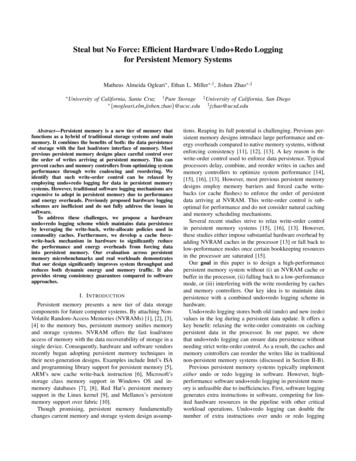
3 ConfigurationThe following steps explain how to configure the operation log function.3.1Configuration ScreenGo to “Setup” menu and select “Data Log Settings”.3.2Channel SetupThe “Data Log Settings” dialog box allows you to configure the function.You can use up to 20 channels and each channel can have the maximum 128 deviceaddresses, but you can only use up to 128 device addresses in the total of the LoggingData function. For example if you set 128 device addresses for channel 1, you can notuse other channels.To set the configuration of channel, select the channel number and click “Edit”.
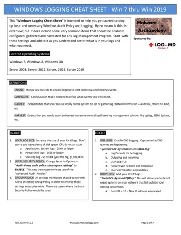
3.3General SettingsBasic SettingsTo use the channel, you have to change the “Log function” to “Enable”, and set thedevice address, which you want to monitor, to “Source”.In addition, choose the “Sampling Method” and set the time or Device.Source: You can set any HMI or PLC Word Device.Sampling Method:Fixed Period: Source device value is recorded every fixed period which you set.Event Bit: Source device value is recorded when the Device is turned ON.This method may be proper if you want to record device value when the specificevent happens such as alarm.Event Word: Source device value is recorded when the Device value is changed.If you want to record the Source device value when only the value is changed,you can set the same device address to both Source and Device.
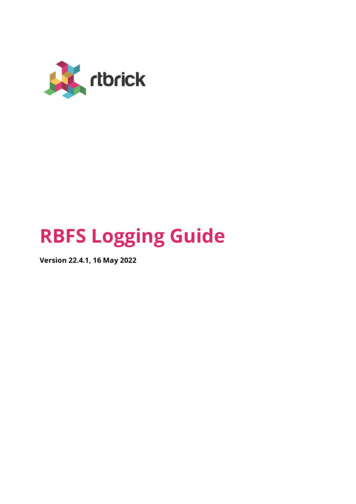
Threshold Settings (Optional/HG2G only)All Logging data are stored into HMI internal memory, but if the memory capacity isfull, the old data will be overwritten by the new data.If you don’t want to overwrite the old data, you can use the following settings and showa message or store the logging data to CF Card.You can monitor the number of record and the percentage of memory capacity.The Number of Stored DataThe number of record is saved to the device which is set to “Monitor Number of StoredData”, and if you want to do something when the number of record reaches to thethreshold value, check the “Report when Number of Stored Data has reached orexceeded Threshold” and set the threshold value and report device. When the number ofrecord reaches or exceeds the threshold value, HMI turns ON the Report Device.You can set Word Device as “Monitor Number of Stored Data” and Bit Device as“Report Device”.The percentage of Stored DataIf you check “Monitor % Space Used in Data Storage Area”, HMI write the percentageof used memory to the device address. In addition, if “Report when % Space Used hasreached or exceeded Threshold” is checked, HMI turns ON the Report Device when thepercentage of Stored Data reaches or exceeds the threshold value.
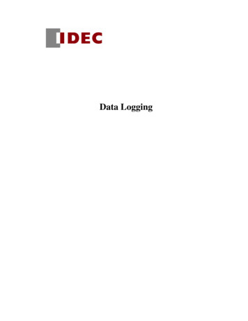
3.4Data SettingsTarget Device Addresses and Display FormatIf you want to record only one device address, you don’t have to change this setting, butif you wan to record more than one device addresses in this channel, you need to change“Number of Data”.Display format and TextThe following settings affect to CSV file. If you use Data Logging for trend chart, youdon’t need to configure these settings.Title of Sampling TimeIn the Logging data file, the logging data consist of sampling time and device value, andthey have titles. The default title name of sampling time is “Sampling Time”, but if youwant to change the name, you can change it to anotherData Type and Display Type (Decimal/Hexadecimal)If you want to change the data type of each device address or display type, you candouble click on the row, or select the row and click “Edit” button. Or if you want tochange the all data type in the channel, click “Auto” instead of “Edit”.
3.5CF Card Output Settings (Optional)For HG2F/3F/4F, they have CF Card Slot, and HMI can save the Logging data to theCF Card. In this tab, you can use “Batch” output and “Real Time” output.BatchIf “Batch” is checked, HMI writes logging data to CF Card when the trigger device isturned ON.Real TimeIf “Real Time” is checked, HMI writes logging data to CF Card when new data arelogged. (HMI can only write the data every 3 minutes. In other words, the latest datamay not be written to CF card for 3 minutes.)File Name SettingsBatch and Real Time have the different file name, and you can add 3 digits numberbetween the file name and extension.This function can be used to identify the date of the logging data, for example, if youwant to store logging data every day for a month, you can put day between the file nameand the extension.( LOGO01 01.CSV – LOGO01 31.CSV )
3.6Option Settings – Logging Data Copy (Option)
3.7Data Storage Area SettingsIf you use HG2G, you will see the following message when you close the “IndividualSettings” dialog box because you have not assigned any Data Storage Area to loggingdata.To solve this issue, you need to click “Yes” and go ahead next dialog box.The capacity of logging data is set to 0 as the default setting. To use data logging, youhave to increase this value. You need to consider how many data you want to takelogging, and put the maximum number of logging to this setting.Note:The required size of the storage area depends on the number of the maximum data pointand the number of device addresses which you set in the Logging Setting. For example,if you set 10 as the maximum data point and 10 device in a channel, this data occupy260 bytes in the Data Storage Area. Another example, if you set 1 device address and 10data points, this occupies 80 bytes.
3.8Clear Logging DataThe Logging data in the HMI memory can be erased by this function.To erase the Logging data, you need to set a bit device address to “Clear Log Data” andturn ON this bit device value.Note:This function doesn’t erase the Logging data in CF Card.
4 How to use Logging Data4.1Trend ChartTo display the Logging data as Trend Chart, follow the steps below.Step.1Put a Trend Chart on the screen from Tool Bar or Main Menu.
Step.2To set properties, double click the Trend Chart.First of all, you need to select “Chart Type”.Log Trend (Normal): Line starts from left side.Log Trend (Pen Recorder): Line starts from right side.
Step.3Go to “Pen (Log)” tab and set line parameters.At least, you have to set any channel number and data number to display a graph.To set the parameters, you need to click “Set” after select Channel No., Data No, LineType, Line Size and Line Color.After set more than one line, click “OK” and close this dialog box.Channel No. : Select the channel number.Data No. : Select the data number in the channel.(This property is only for HG2G. If HMI is not HG2G, this parameter is fixed to 1.)Example:If you want to display LDR 2 value as Trend Chart, Channel No. is 2, and Data No is 3.Ch No.123SourceDeviceD0LDR 0LKR 0Data No.1D0LDR 0LKR 02D1LDR 1LKR 13D2LDR 2LKR 24D3LDR 3LKR 3
4.2Logging Data Output as CSV file formatFile NameHMI creates 2 types of Logging Data in the CF Card. One of them is Batch output file(LOGO01.CSV), and the other one is Real Time output file (LOGA01.CSV).These file names may be changed by the following settings.
Upload the logging data from HMI Internal Memory usingDownloader softwareDownloader software allows you to upload the Logging Data from HMI InternalMemory.Step.1Launch Downloader software and go to “Upload” and select “Data Log Data”.Step.2Set a path to save the logging data and click OK.Step.3You can find out “LOG01.CSV” in the folder after uploading completed.
Upload the logging data from CF CardHG2F/3F/4F has a CF Card slot, and the Logging data can be stored to the CF Card.If you want to store the Logging data to the CF Card, check “3.5CF Card OutputSettings (Optional)”.To upload the logging data form the CF Card, you have 3 ways.WindO/I-NV2 softwareStep.1Go to “Online” - “CF Card Maintenance” - “Upload”Step.2Check “Data Log Data”, and set a path for the upload data and click OK.Step.3You can find out “LOG01.CSV” in the folder after uploading completed.Note: If you use Ethernet to upload the data, you will see the folder which is the samename of the IP address of HMI. The upload data is saved in the folder.
Downloader softwareStep.1Go to “CF Card Maintenance” - “Upload”Step.2Check “Data Log Data”, and set a path for the upload data and click OK.Step.3You can find out “LOG01.CSV” in the folder after uploading completed.Note: If you use Ethernet to upload the data, you will see the folder which is the samename of the IP address of HMI. The upload data is saved in the folder.
CF Card ReaderYou can copy the Logging data from the CF Card using CF Card Reader (Memory CardReader) and file manager software. The Logging data files are stored under“\HGDATA01\Log” folder.The Logging data files are saved into the folder as CSV file format, so you can openthem using Text Editor or spreadsheet software.
Upload the logging data from CF Card HG2F/3F/4F has a CF Card slot, and the Logging data can be stored to the CF Card. If you want to store the Logging data to the CF Card, check "3.5CF Card Output Settings (Optional)". To upload the logging data form the CF Card, you have 3 ways. WindO/I-NV2 software Step.1