Transcription
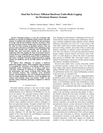
User ManualData Logging Sound Level Meterwith NIST-Traceable CalibrationModel 20250-29THE STANDARD IN PRECISION MEASUREMENT
IntroductionThe Digi-Sense Data Logging Sound Level Meter(Model 20250-29) measures sound decibel levels fornoise certification and reduction applications. The meterconforms to IEC61672-1 Class 2 standard. Advanced features include data Hold, Max/Min readings, low/medium/high ranges, over and under range, and A and C weighting.The unit offers Fast/Slow response, analog AD/DC outputs,USB connectivity, data logging software, backlight display,and automatic power-off. The instrument is fully tested andcalibrated to NIST-traceable standards. Careful use ofthis meter will provide years of reliable service.UnpackingCheck individual parts against the list of items below.If anything is missing or damaged, please contactyour instrument supplier immediately.1. Meter2. Windscreen3. Earphone plug, 3.5 mm4. Screwdriver5. Three AAA batteries6. USB cable7. Software8. User manual9. NIST-traceable calibration report with data2
Key Features Wide measurement ranges of 30 to 130 dB Precision accuracy of 1.4 dB Meets IEC61672-1 Class 2 standard User selectable low/medium/high, and auto rangemeasurement levels A and C frequency weighting Fast and slow time weighting Memory of 32,700 readings Max/Min and Hold functions Over- and under-range indicator AC/DC analog outputs Data logging software with graphical display Download data via USB connectivity Large backlit LCD for easy reading Low-battery indicator Auto power-off after fifteen minutes ofnonuse to conserve battery power3
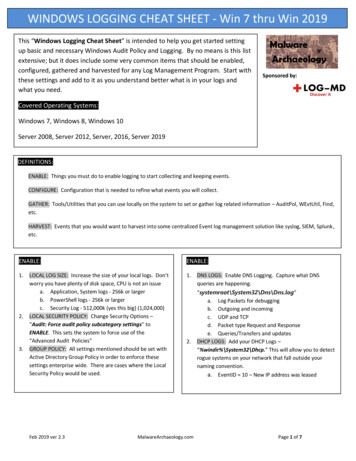
Meter Description1. Windscreen2. LCD3. REC button4. SETUP button5. FAST/SLOW button6. MAX/MIN button7. LEVEL button8. Backlightbutton9. A/C frequency weighting10. HOLD button11. Power on/off button12. External DC 5V powersupply terminal13. USB interface14. AC/DC signal outputearphone outlet15. Calibration potentiometer16. Tripod mounting screw17. Battery cover18. Microphone4
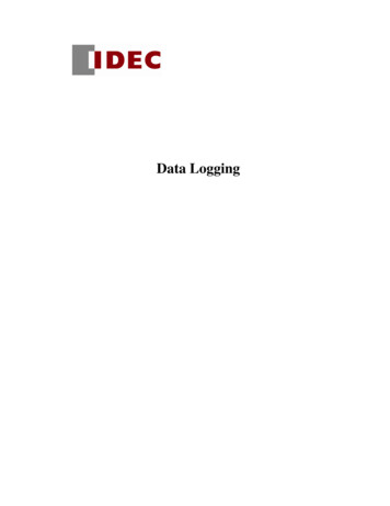
Display Layout1. Under-range icon10. Auto power-off2. Over-range icon11. Low-battery3. Maximum hold icon12. Recording icon4. Minimum hold icon13. Memory full icon5. Fast response icon14. A-Weighting icon(response to human sense)6. Slow response iconiconindication7. Selected level range15. C-Weighting icon(response to machinery)8. Date and time symbols16. Auto level range selection9. Reading of sound level17. Data Hold function icon451236789101611171213 14155
Setup and Operation1. Remove the battery cover on the back and put in threeAAA batteries. Replace the battery cover.2. See Data Zero Function below to set before poweringunit on.3. Press the Power on/off button to turn the meter on.4. Press the LEVEL button to select your desired low/medium/high or auto level. (Note: With selected range,ensure that the UNDER or OVER icon is not displayed,which indicates you are out of range.)5. Select dBA for general noise sound level or dBC formeasuring sound level of acoustic material.6. Select FAST for instant sound and SLOW for averagesound levels.7. Hold the unit in hand or fix-mount it on a tripod andmeasure sound level at a distance of 3.3 to 4.9 feet(1 to 1.5 meters).Data Zero Function1. Before powering on, press and hold theREC button.2. While holding the REC button down, pressand hold the Power on/off button until thedisplay reads CLR. This indicates that thedata in memory has been deleted.6
Enabling the Data Logging Function1. Press REC button after powering unit on.2. The display will show REC and the unit will beginlogging data.3. Press the REC button again to exit recording. (Note: Inorder to avoid data errors, do not power the unit offwhile in REC mode. To ensure data integrity, deselect theREC function prior to powering meter off.)Time and Date Setup1. Press and hold the SETUP button. Whileholding the SETUP button, press andhold the Power on/off button. When theTIME symbol appears on the display,release the SETUP button. The meter isnow in the time and date setup mode(see Fig. 1).Fig. 12. Press the SETUP button a second time(see Fig. 2).3. While viewing the display above, pressthe LEVEL button to set the minute.Then press the HOLD button to savethe desired minute.Fig. 24. Press the SETUP button a third time(see Fig. 3).5. While viewing the display above, pressthe LEVEL button to secure the desiredhour (AM or PM). Then press the HOLDbutton to save the desired hour.Fig. 36. Press the SETUP button a fourth time(see Fig. 4).Fig. 47
Time and Date Setup (Continued)7. While viewing the display (see Fig. 4),press the LEVEL button to choose thedesired day of the month. Then pressthe HOLD button to save this day.8. Press the SETUP button a fifth time(see Fig. 5).9. While viewing the display (see Fig. 5),press the LEVEL button to select thedesired month of the year. Then pressthe HOLD button to save this month.Fig. 4Fig. 510. P ress the SETUP button a sixth time(see Fig. 6).11. While viewing the display (see Fig. 6),press the LEVEL button for the desiredyear. Then press the HOLD button tosave the year. This completes the setupprocess.12. Press the SETUP button a seventh time(see Fig. 7). This is the time/date resetfunction. Press the HOLD button to save.The time and date will then return to theoriginal factory time and date setup.Fig. 6Fig. 7(Note: When the batteries fail or are replaced,you may have to reprogram the time/date.Simply follow steps #1 through #11 above.)Selecting Time WeightingPress the FAST/SLOW button to select fast or slowsampling times. FAST sampling measurement ofone time per 125 mS. SLOW sampling measurementof one time per second.8
Viewing the Min and Max Readings1. Press the MAX/MIN button once and MAX icon willappear on the display. In this mode, the maximumsound level will be captured and held until a highersound level is captured.2. Press the MAX/MIN button again and the MIN iconwill appear on the display. In this mode, the minimumsound level will be captured and held until a lowersound level is captured.3. Press the button one more time to exit theMAX/MIN function.Selecting Level RangePress the LEVEL button to select low/medium/high, orauto decibel measuring range. The selected range willappear in the upper left and upper right of the display.LCD BacklightPress the Backlightdisplay backlight.button to activate or deactivate theSelecting Frequency WeightingPress A/C button to select A or C weighting. Either thedBA (A-weighting) or dBC (C-weighting) icon will bedisplayed.Freezing the ReadingPress HOLD button to freeze the reading in the display.9
Connecting the USB Cable1. Turn on the meter and connect the USB cable to theUSB port located on the side of the meter.2. Connect the other end of the USB cable to thecomputer.3. Choose the software COM3 (COM).4. Press the SETUP button. The auto power-officonwill disappear from the display, indicating the disablingof the auto power-off function and the successfultransmission of USB data. The USB signal output isa 9600 bps serial interface.Installing Software1. Insert the CD into the PC.2. Run SETUP.EXE on the CD. Follow the installationwizard to complete the installation.3. Upon successful installation, the Sound Level Metersoftware icon shortcut will be automatically placed onthe PC desktop.4. If the USB driver needs to be updated (or if youreceive the driver error message), go to the folderwith the driver on the CD and double click the fileCP210xVCPInstaller.exe to update the driver. (Withdisk in the computer, D drive/USB Driver folder).Activating Real-Time Data Logging1. Once the driver software is installed, start the application software by selecting the Auto (A) function fromthe Com Port dropdown menu at the top of the menubar. Then connect the meter to the computer via theUSB cable.10
2. M ake sure the auto power-officon does not appearin the instrument display by pressing the SETUP button.When this symbol is not displayed, the meter is transmitting data to the computer.3. Select the Real Time (R) from the top menu bar; selectSetup (U) from the dropdown menu.4. In the Setup menu screen, select the preferred RealTime Sampling Rate then press Start.5. You may stop the data logging function by selecting theStop symbol located at the top of the menu bar. Simplyselect the Excel document symbol at the top of themenu bar to instantly download your current datasession to the preformatted Excel document.6. T o set A and B cursors, simply double click on thegraphical display of data taken and the cursorinformation will automatically populate within thecursor designated box.Remote Data Logging/ Downloading Data1. C lear all data from the instrument. See Data ZeroFunction instructions on page 6.2. Set the unit to your desired sampling speed, frequencyweighting, and level settings (see pages 8–9).3. Press REC button to begin recording data. The REC iconwill be displayed in the lower left of the display.4. When data recording is complete, push the REC buttonagain to stop the data logging function. The REC iconshould disappear from the lower left of the display.11
Remote Data Logging/ Downloading Data (continued)5. Connect the meter to the computer via the USB cable.See Connecting the USB Cable section on page 10.Select the Sound Meter icon from your desktop.(Note: Software must already have been successfullyinstalled.)6. Make sure auto power-officon is not displayedin the screen. Press SETUP button to deactivate ifnecessary.7. In the sound level meter software screen, selectData logger (D) from the top menu bar.8. The summarized record of data will then automaticallydownload to the screen and be tagged with ID, Date/Time, Unit, Sampling Rate and Nums information.9. Select Export to Excel (E) from the top menu bar toexport data to Excel if desired.10. D ouble click on summarized data logging record tographically view the data on the screen.Connecting to the External 5 VDC Power Supply TerminalTo connect with the 5 VDC power supply, the aperturesize is: external diameter 3.5 mm, internal diameter 1.35 mm.12
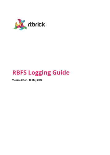
Using the AC/DC Signal Output EarphoneDC:Output voltage: 10 mV/dBOutput impedance: 1 kΩDCOUTPUTAC:Output voltage: 1 Vrmscorresponding to eachrange stepOutput impedance: 100 ΩACOUTPUTGROUNDUsing the Calibration PotentiometerThe CAL function is for externalstandard level calibration adjustments. (Note: The meter is calibrated against NIST-traceablestandards before shipment.) Tomake calibration adjustments offrequency weighting (A-weighting),time weighting (FAST), or Levelrange (50 to 100 dB):1. Insert the microphonehousing carefully intothe 1 2" insertion holeof the calibrator(94 dB @ 1 KHz).2. Turn on the switch of calibrator and adjust the CALpotentiometer of the unituntil 94.0 dB is displayed.13
SpecificationsRangeResolutionAccuracyWeightingTime weightingFunctionsMax/Min, Hold, Low/medium/highranges, Over-range, Under-range,A and C weighting, Fast/Slow response,Memory, Data logging software, Backlitdisplay, and Automatic power-offFrequency rangeDynamic rangeMemoryDisplay updateConnectivity31.5 Hz to 8 kHz50 dB32,700 readings2 times/secUSBAnalog outputAC/DC outputs from earphone outlet;AC 1 Vrms, DC 10 mV/dBMicrophoneOperating conditionsStorage conditionsApprovalsDisplayDimensions (L x W x H)PowerWeight14Low: 30 to 80 dBMedium: 50 to 100 dBHigh: 80 to 130 dBAuto: 30 to 130 dB0.1 dB 1.4 dBA and CFast 125 m/sec, Slow 1 sec1 2 "electret condenser microphone32 to 104 F (0 to 40 C); 10 to 90% RH14 to 140 F (–10 to 60 C); 10 to 75% RHIEC61672 -1 Class 24-digit backlit LCD with bar graph91 4" x 27 16 " x 11 16 " (235 x 61 x 27 mm)Three AAA batteries9.8 oz (280 g)
Maintenance, Recalibration, and RepairMaintenance When operating the meter in the presence of wind, usethe included windscreen to eliminate undesirable signals. Keep microphone dry and avoid severe vibration.Cleaning & Storage Meter should be wiped regularly with a dry cloth;do not use solvents or detergents to clean meter. Do not store or operate the instrument in hightemperature and humidity environments (seeSpecifications on page 14).Battery ReplacementWhen the low-battery icon appears on the screen, replacethe three AAA batteries in the rear battery compartmentby loosening the screws and removing the battery door.Ensure cover is securely refastened when finished. Removebatteries if unit is not being used for extended time periods.It is recommended that Digi-Sense products are calibratedannually to ensure proper function and accurate measurements; however, your quality system or regulatory bodymay require more frequent calibrations. To schedule yourrecalibration, please contact InnoCal, an ISO 17025calibration laboratory accredited by A2LA.Phone: 1-866-INNOCAL (1-866-466-6225)Fax: 1-847-327-2993E-mail: sales@innocalsolutions.comWeb: InnoCalSolutions.com15
For Product and Ordering Information, Tel: (866) 433-6682Fax: (866) 433-6684Tel: (281) 359-8538Fax: (281) 359-00841065DGMAN 20250-29 Rev.1Manual Part No. 00100-60
Enabling the Data Logging Function 1. Press REC button after powering unit on. 2. The display will show REC and the unit will begin logging data. 3. Press the REC button again to exit recording. (Note: In order to avoid data errors, do not power the unit off while in REC mode. To ensure data integrity, deselect the REC function prior to .