Transcription
PHYSICS SL INTERNAL ASSESSMENTAN INVESTIGATION INTO THE EFFECT OF THE DISTANCE AT WHICH A FORCE IS APPLIED TO THEMAXIMUM DEFLECTION OF A CANTILEVER BEAMRESEARCH QUESTIONHow does the distance at which a force is applied from the point of suspension of a cantilever beam affect the cantilever’smaximum deflection?AIM OF INTERNAL ASSESSMENTThe aim of this internal assessment is to determine the relationship between the distance at which a force is applied to acantilever and its maximum deflection. This will be done by experimentally determining the maximum deflection of acantilever with a mass applied at different distances from the point of suspension and comparing these results to theoreticalpredictions to see how closely the theory fits the practical.INTRODUCTIONI found myself initially interested in the properties of cantilevers whilst on a family trip in Austria. As we hiked through theAlps, we came across several viewpoint platforms which were fixed at their base and suspended high above the valley. As Iwalked across the platform, I wondered how engineers were able to ensure that the viewpoint wouldn’t deflect or break,regardless of the number of people on the platform and where they stood. Whereas some forces, such as my weight forceacting on the platform, were easy for me to conceptualize, the effect of these forces as I walked further along the platformwere harder for me to conceive. Following this experience, I was motivated to further explore the behaviour of cantileversunder the effects of certain factors, such as the distance at which a force was applied. As such, I decided to explore therelationship between the distance at which a force is applied to the maximum deflection of a cantilever beam.BACKGROUND THEORYBeams are structural components which are critical elements in the foundation of architectural structures1. Beams can havevarious shapes but this investigation will consider cuboid-shaped beams, as these are most common in real life. Beams areoften characterized according to their boundary conditions (the ways in which they are supported), which is the main factorthat makes different beams to deflect differently when subjected to an external force. A cantilever is specifically characterizedas a beam which is “fixed at one end and free at the other”2. “At the fixed end (e.g. a clamped support) a cantilever can’tdeflect or rotate, whereas at the free end it may do both”3. Similarly to how there are beams with different boundaryconditions, there are also different types of loads which can exert a force on a section of a beam. The two types of loads whichwill be investigated in this investigation are point loads (loads that are concentrated at a specific points on a beam) anduniformly distributed loads (loads which are uniformly distributed across the entire length of a beam)4. Ultimately, a forceacting on a cantilever causes it to displace from its initial, unloaded position to a subsequent, loaded position5. This is knownas deflection.As part of this investigation, it is important to understand which forces cause a cantilever to deflect. Once it is deflected,a cantilever is in a state of equilibrium, meaning that the vector sum of the forces acting on the cantilever are balanced6. Thereason for the cantilever’s deflection is partly due to a weight force, such as an applied external load, which acts downwardson the cantilever. Additionally, a positive bending moment will be induced at the fixed end of the cantilever when it issubjected to an external force7. The bending moment at the fixed end of a cantilever will be in a clockwise direction,effectively causing the cantilever in question to deflect downwards. This bending moment is measured in Newton meters(Nm) and is equal to the product of the weight force applied to the cantilever in Newtons (N) and the distance at which thisforce is applied from the cantilever’s suspension point in meters (m)8.Given the numerous forces which can be involved in the deflection of a beam, beam deflection equations have beenderived to explain the maximum deflection of a beam based on the beam’s composition, geometry and the conditions underwhich a force is applied to it. In order for these equations to be applicable, there are a set of assumptions which must be madeabout the beam in question. These include that the beam is “originally straight and all of the forces applied to the beam act in1Gere, James M., Stephen Prokofevich Timoshenko, and T. Chris. Evensen. Mechanics of Materials. Boston: PWS, 1997.Ibid.3Ibid.4“TYPES OF BEAMS & TYPES OF LOADINGS.” TYPES OF BEAMS & TYPES OF LOADINGS, December 3, 2/types-of-beams-types-of-loadings.html.5“Zoe Liang.” SkyCiv Cloud Structural Analysis Software, February 21, 2019. hat-is-deflection/.6“The Physics Classroom Tutorial.” The Physics Classroom. Accessed November 15, s/Lesson-3/Equilibrium-and-Statics.7“Zoe Liang.” SkyCiv Cloud Structural Analysis Software, February 21, als/what-is-bending-moment/.8Ibid.21
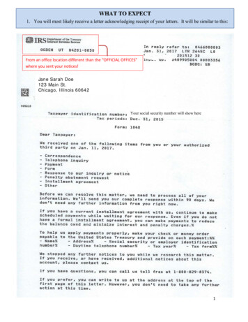
the same plane”9. When considering these assumptions, the maximum deflection of a cantilever which is subjected to a pointload is characterized by equation (1) below:a2δ max point load F6EI(3l a)equation (1)10In equation (1), δmax point load is the maximum deflection of the cantilever in metres (m), F is the force applied to the beam inNewtons (N), a is the distance of the force applied from the cantilever’s point of suspension in metres (m), E is the Young’smodulus of the cantilever in Pascals (Pa), I is the area moment of inertia of the cantilever’s cross-section in meters to thefourth power (m 4 ), and l is the suspended length of the cantilever beam in metres (m).The Young’s modulus and area moment of inertia are important properties toexplain when discussing the behaviour of beams. The Young’s modulus is afundamental property of a material that describes the “the material’s ability to resistchanges in length when under lengthwise tension or compression”11. Critically, theYoung’s modulus is an indication of the “stiffness” of a material12. The greater thevalue of the Young’s modulus, the “stiffer” a material is and the less it will deflectwhen subjected to a force. The value of the Young’s modulus for a certain materialis temperature and pressure dependent13. An increase in temperature or decreasepressure conditions will decrease the Young’s modulus making, thus making it less“stiff”14. The area moment of inertia is a property which describes the “ability of across-sectional shape to resist bending”15. The greater the value of the area momentof inertia for a given object, the more “effective” it is in resisting bending fromexternal forces. While the area moment of inertia can be determined for a variety ofshapes, this investigation considers cuboid beams, whose cross-section consists of a“rectangle about its centroid axis”16 as illustrated in Figure 1. This particularcross-section simplifies the equation required to calculate the area moment of inertiaof a cuboid beam, as shown in equation (2):area moment of inertia of a cuboid beam bh312Figure 1: the cross-section of acuboid beam around a centroidaxisequation (2)17In equation (2), b is the breadth of the cuboid beam’s cross-section in metres (m) and h is the height of the cuboid beam’scross-section in metres (m). Evidently, increasing both the breadth and height of a cuboid beam’s cross-section increases itsarea moment of inertia value and thus its ability to resist bending.One important assumption made in equation (1) is that the cantilever in question is weightless. This is evident given that, ifthe force on the beam ( F ) was zero, the maximum deflection would also be zero. This assumption isn’t applicable to real lifewhere cantilevers aren’t weightless given that they have a mass and are acted upon by the force of gravity. Ultimately, theweight of a cantilever can be thought of being a uniformly distributed load across the suspended length if a cantilever, thuscausing the cantilever to deflect. The maximum deflection of a cantilever which is subjected to a uniformly distributed load ischaracterized by equation (3) below:δ max unif ormly distributed load ωl48EIequation (3)18The variables in equation (3) are identical to the ones shown in equation (1). The new variable, ω , is the uniformlydistributed load on the cantilever expressed as force per unit length (Nm -1 ). Essentially, this is equal to the weight of thecantilever in Newtons divided by its suspended length in metres.9“Beam Deflection Tables.” MechaniCalc. Accessed November 15, 2019. tables. equation 1 : “Cantilever Beams - Moments and Deflections.” Engineering ToolBox. Accessed November 15, -beams-d 1848.html.11“Young's Modulus.” Encyclopædia Britannica. Encyclopædia Britannica, inc., July 3, 2019. 12Ibid.13Young's Modulus. Accessed November 15, 2019.https://depts.washington.edu/matseed/mse resources/Webpage/Biomaterials/young's modulus.htm.14Saxena, Vimal, Michel Krief, and Ludmila Adam. Handbook of Borehole Acoustics and Rock Physics for Reservoir Characterization. Saint Louis:Elsevier, 2018.15“2nd MOMENT of AREA.” Area Moments. Accessed November 15, 06A/Area Moment/Area Moment.html.16“Zoe Liang.” SkyCiv Cloud Structural Analysis Software, February 21, -section/.17 equation 2: Ibid.18 equation 3: “Cantilever Beams - Moments and Deflections.” Engineering ToolBox. Accessed November 15, -beams-d 1848.html.102
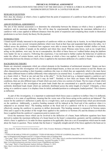
In this investigation, the maximum deflection of a cantilever which is subject to both a uniformly distributed load (itsown weight) and a point load (an attached mass) will be investigated. In order to determine the maximum deflection of thecantilever due to both of these loads the “method of superposition”19 can be used. Similarly to how the interference pattern ofwaves can be deduced by calculating the vector sum of the displacements of each individual wave, the maximum deflection ofa beam which is subject to multiple forces is equal to the vector sum of the maximum deflections caused by each individualforce applied. Given the assumption that all loads acting on the cantilever are doing so in the same plane (and in the samedirection), the maximum deflection caused by each individual will have a positive value. Therefore, the maximum deflectionof a cantilever beam subjected to both a uniformly distributed load ( ω ) and a point load ( F ) is the sum of equations (1) and (3)which illustrate the maximum deflection due to a point load and uniformly distributed load respectively. This sum is shown inequation (4) below, alongside a depiction of the effects of a point load and a uniformly distributed load on a cantilever’sdeflection in Diagram 1.Diagram 1: t he deflection of a cantilever which is subject to a point load(F) and a uniformly distributed load (ω) - self-made diagramδ max δ max point load δ max unif ormly distributed load ωl48EI P a26EI (3l a)equation (4)APPROACH TO THE RESEARCH QUESTIONWhen approaching how to answer the research question, alternate methods were considered which would simplify thelinearization of the relationship between the cantilever’s maximum deflection and the distance at which a force is applied to it.The equation expressing the maximum deflection of the cantilever beam due to a uniformly distributed load and a point load(equation 4) is complex and difficult to linearize. Instead of attempting to linearize this equation, it was chosen to adopt amethod which would account for the “natural” deflection of the cantilever beam (the cantilever’s maximum deflection due toits own weight, a “uniformly distributed load”), effectively removing the "δ max unif ormly distributed load " element of equation (4)and making the equation to be linearized equal to equation (1). When considering equation (4), it is evident that themagnitude of the cantilever's maximum deflection caused by a uniformly distributed load is independent of the maximumdeflection due to the point load, since the two are added together. Therefore, if the Young’s modulus ( E ), area moment ofinertia ( I) and length ( l) remain constant, the maximum deflection of a cantilever due to the uniformly distributed load willalso remain constant. Considering this has allowed me to account for the cantilever’s natural deflection in the methodology bycalculating the maximum deflection of the cantilever as the difference between the initial displacement of the cantilever dueto its own weight and the displacement of the cantilever with an attached mass from the floor. The initial displacement wouldbe measured at the start of each trial and assumed to be constant for the remainder of that trial. Ultimately, this would ensurethat the maximum deflection values at each distance are exclusively due to the attached mass.LINEARIZING THE EQUATIONFollowing the adopted methodology explained previously, it is only necessary to linearize equation (1) in order to graph alinear relationship between the maximum deflection of the cantilever and the distance at which a force is applied to it. In orderto linearize this equation, we must convert it into the standard “y mx c” form. The process of linearizing equation (1) isshown below.2 δ max19aδ max F6EI(3l a)F δ max 6EI (3la2 a3 )F ma3 ca2 (m 6EI, c equation (1)Fl2EI )“Structural Analysis.” Engineer4Free. Accessed November 15, 2019. html.3
δ maxa2 ma c (m F
p h ys i cs s l i nt e rnal as s e s s m e nt an investigation into the effect of the distance at which a force is applied to the maximum deflection of a cantilever beam