Transcription
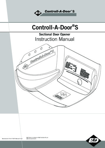
S Controll-A-Door SSectional Door OpenerInstruction ManualManufacturer’s Part # 79079 (Manual) V1.02B&D Doors is a division of B&D Australia Pty LtdABN 25 010 473 971www.bnd.com.au
2Controll-A-Door S Instruction ManualControll-A-Door SSectional Door OpenerSafety RulesDefault Settings & SpecificationsAbout Your Opener030405Operating Controls06Kit Contents08Installation09C-Rail Attachment09Determine Door Type10Battery Back Up Installation21Mounting - Track Type Door11Solar Power System Installation22Mounting - Non-Track Type Door12How To Use Your Opener24Mounting Door Bracket & Arms13Transmitter Battery2414Locking2414Manual Release24Testing Safety Obstruction Force15Power Failure24Safety Obstruction Force Test15Safety Infra-red Beam25Adjusting Safety Obstruction Forces15Courtesy Light2516Auxiliary Output25For Door Operation16Vacation Mode25For Courtesy Light Operation16Setting The Pet Mode Position25For Vacation Mode17Maintenance26For Auxiliary Output17Troubleshooting Guide27For Pet (Pedestrian) Mode18Parameters28Deleting All Transmitter Codes18Spare Parts30Mounting Wall Transmitter18Warranty32Programming the OpenerSetting Travel Limits - Control PanelCoding TransmittersAccessories19Terminal BlockRemote Aerial1919Electric Key Switch19Safety Infra-red Beam20
Controll-A-Door S Instruction ManualSafety RulesPlease read these important safety rulesThese safety alert symbols indicate a personal safety or property damageinstruction exists. READ THESE INSTRUCTIONS CAREFULLY.This automatic garage door opener is designed and tested to offer safeservice provided it is installed and operated in strict accordance with thefollowing safety rules. Failure to comply with the following instructions mayresult in death, serious personal injury or property damage.CAUTION: If your garage has no pedestrian entrancedoor, an emergency access device should be installed.This accessory allows manual operation of the garagedoor from outside in case of power failure.Position the Garage Door Opener so that the power plugis accessible when inserted into the power outlet (EN60335-1).This opener should be installed in accordance with relevantAustralian Standards.Do not allow children to play with door controls.Keep transmitters away from children.Watch the moving door and keep people away until thedoor is completely opened or closed.Activate the opener only when the garage door is in fullview, free of obstructions and with the opener properlyadjusted.Keep the garage door balanced. Sticking or bindingdoors must be repaired. Garage doors, door springs,brackets and their hardware are under extreme tension andcan cause serious personal injury. Do not attempt any garagedoor adjustment. Do not use if repair or adjustment is needed.Call for professional garage door service.Install the optional wall transmitter in a location where thegarage door is visible, but out of the reach of children ata height of at least 1.5m.Do not wear rings, watches or loose clothing whileinstalling or servicing a garage door opener.This opener is not suitable for commercial, industrialor common entry applications.To avoid serious personal injury from entanglement,remove all unnecessary ropes or chains and disableany equipment such as locks which are not needed forpowered operation.Installation and wiring must be in compliance withyour local building and electrical codes. Connectthe power cord only to properly earthed mains. If anextension lead must be used, make sure it is a 3-core leadand approved to 7 amp capacity.If the power cord is damaged, it must be replacedby the manufacturer, its service agent or a similarlyqualified person in order to avoid a hazard.This opener is a plug in domestic appliance and isdesigned for indoor use only. It must be installed ina dry position that is protected from the weather.The opener is not intended for use by young childrenor infirm persons without supervision.WARNING! It is vital for the safety ofpersons to follow all instructions. Savethese instructions.Disconnect electric power to the garage door openerbefore removing covers.Doors requiring over 400N of force to move must haveSafety Infra-red Beams fitted.B&D Doors to the extent that such may be lawfully excluded hereby expressly disclaims all conditions or warranties, statutory or otherwise which may be implied by laws asconditions or warranties of purchase of a B&D Garage Door Opener. B&D Doors hereby further expressly excludes all or any liability for any injury, damage, cost, expense or claimwhatsoever suffered by any person as a result whether directly or indirectly from failure to install the B&D Garage Door Opener in accordance with these installation instructions. Copyright 2009 B&D DoorsD Power Drive : Instruction Manual3
4Controll-A-Door S Instruction ManualDefault Settings & SpecificationsFactory default settingsDefaultStepMinimumMaximumCourtesy light time3 minutes10 Sec in batterybackup mode-3 minutes10 Sec in batterybackup mode-3 minutes10 Sec in batterybackup mode-Obstruction force margin0.7 amps0.1 amps02.0 ampsTechnical specificationsPower supply230V - 240Va.c. 50HzTransformer rating24Vd.c.Standby power2.2 WattsMotor power100 WattsMotor type24Vd.c permanent magnetShuttle travel distance in the C-Rail2.7m approx. (standard)*Maximum shuttle travel distance in the C-Rail3.750 m (with one extension)*Maximum door opening:Width:Height:Weight:5500mm (16.5m2)2150mm100kgMinimum headroom25mmShort term peak force700N (70kg)Lift force450N (45kg)Nominal force150N (15kg)Receiver typeUHF Multi-frequency FM ReceiverReceiver code storage capacity8 X 4 button Transmitter CodesTransmitter frequency433.47, 433.92, 434.37 MHzCoding typeTri-Tran Number of code combinationsOver 4.29 billion random codesCode generationNon-linear encryption algorithmTransmitter batteryCR2032 (3 Volts)Courtesy lightFestoon style lamp 24 volts 15 wattController fuse10A slow blow*The actual travel of the door depends on configuration of the connecting arms.Note: Intermittent operations may occur in areas which experience very strong winds. The strong wind puts extra pressureon the door and tracks which may in turn intermittently trigger the safety obstruction detection system.
Controll-A-Door S Instruction ManualAbout Your B&D OpenerThank you for choosing a Controll-A-Door S automaticgarage door opener, designed and developed in Australiaby B&D Doors.Battery Back UpThe technically advanced construction of this openerensures you enjoy the following benefits:In case of a power failure the opener does not lose thetransmitter codes or limit settings.WarrantyOptional Battery Back Up or solar power is available.Memory RetentionFive (5) year/10,000 cycles full parts and labour warrantyon motor, electronics and mechanical components ofthe opener when installed by an Approved B&D Dealer(conditions such as annual garage door servicing apply).Soft Start/Soft StopTri-Tran Frequency Hopping TechnologyManual ReleaseEvery time a transmitter is used, it simultaneously sends asignal over three different frequencies, reducing the chanceof interference from other radio frequency sources.Code Hopping TechnologyEvery time a transmitter is used a new security codeis generated from over 4.29 billion possible codecombinations. This greatly enhances the security of thesystem and makes “code grabbing” a thing of the past!Multi-Channel TransmitterMulti-channel transmitters allow you to operate otherdevices such as an adjoining garage door or automatedgate from the same handy unit.Warranty Expired IndicatorThe opener eases into and out of each cycle makingfor smoother and quieter operation, as well as reducingwear and tear on the door and opener.The manual release handle allows the door to beoperated by hand in the event of a power failure.Self LockingThere is no need to manually lock your garage door, asthe opener ‘positively’ locks the door when closed.Periodic Maintenance IndicatorThe SERVICE LED will illuminate to indicate thatperiodic maintenance is required. Contact your dealer/installer for service.Service Fault IndicatorFlashing LEDs on the control panel easily identifyoperational problems or service requirements.The opener will indicate that the number of cycles coveredby the warranty has been reached by flashing the courtesylight 10 times after each operation. This flashing willcontinue for 20 cycles unless it is reset by pressing the SETbutton while the courtesy light is flashing.Dynamic Door ProfilingS-ALPS (Semi Automatic Limits PositioningSystem)An external aerial can be connected for sites whereradio reception is a problem.The S-ALPS system does away with manual adjustment ofthe door’s limits position using mechanical parts, such ascams and microswitches.Safety Reversing SystemThe automatic safety reverse system significantly reducesthe risk of death or serious injury if trapped by a closing door.The safety reverse force can be adjusted for environmentalconditions such as windy areas.Courtesy LightThe courtesy light automatically switches on forapproximately three (3) minutes when operating the door.This can also be programmed to turn on and off from atransmitter.Changing door characteristics are automaticallycompensated for and “learnt” with each operation ofthe door.External AerialVacation ModeA transmitter can be programmed to disable thegarage door opener radio receiver. This is ideal if thedoor is to be left idle for prolonged periods.Pet (Pedestrian) ModeA transmitter can be programmed to open the doorpartially to allow pets access to the garage. The dooropening height is adjustable via a handheld programmer.Auxiliary OutputYou can program a spare button on your transmitter tooperate this output, which can control items that use amomentary close switching mechanism. Copyright 2009 B&D DoorsD Power Drive : Instruction Manual5
Controll-A-Door S Instruction Manual6Operating Controls01.Terminal Block:24V PWR is used to power devices such as Safety Infra-red Beams and external receiver (100 milliamp max).P.E(IR) input is used to connect to Safety Infra-red Beam.P.E(IR) 0V is a 0 volt connection for Safety Infra-red Beam.GND is a common -ve ground for accessoriesOSC is used for the connection of a wired switch (momentary contact). This switch can then be used to open, stopor close the door. Install the wall switch in a location where the switch is out of reach of children and the garage dooris visible.AUX OUT This function allows the opener to operate other devices such as external lights, or an alarm system.02.CODING LED (red) light flashes when a code is being stored or when a transmitter button is pressed.03.DOOR CODE button is used for storing or erasing transmitter buttons for door operation04.SERVICE LED (Yellow) indicates when the opener requires service or repairs.05.SET button (Orange) is used during the installation phase together with the Open and MINUS (-) buttons to set the doorlimit positions. The Set button is also used to re-initialize the Opener.06.OPERATE button (Yellow) is used during installation to test the open, stop and close cycles for the opener. The openerhas to be initialised by the SET button to make the OPERATE button operable.07.FORCE MARGIN SET Button: The obstruction force margin is set automatically during installation. The margin can beadjusted manually using the Force Margin Set button (White). Holding the Force Margin Set button and pressing PLUS( ) or MINUS (-) buttons will increase or decrease the amount of force. The Force Margin Set should only be used ifenvironmental factors (wind, etc.) affect the door’s operation.08.OPEN LIMIT LED (green) the LED is very helpful during installation. It illuminates and flashes when the door is openingand remains steady on when the open limit position has been reached.09.PLUS ( ) button (green) is used during installation to help set the open limit position. Pressing and holding this buttonwill move the door in the open direction, releasing stops the door.NOTE: The safety obstruction detection is inoperable when the PLUS ( ) button is used to move door.10.CLOSE LIMIT LED (red) the LED is very helpful during installation. It illuminates and flashes when the door is closingand remains steady on when the close limit position has been reached.11.MINUS (-) button (red) is used during installation to help set the close limit position. Pressing and holding this buttonwill move the door in the close direction. Movement stops when the button is released.NOTE: The safety obstruction detection is inoperable when the CLOSE button is used to move door.12.DATUM ADJUST SCREW is used during limits set up to indicate the mid point of the door’s travel.13.10A FUSE14.PROG INPUT is used to connect the Handheld “PG-3” Programmer for editing control and receiver functions, accessingdiagnostic tools, and activating special features and operating modes.15.JP1 SOLAR CONNECTOR the shunt must be fitted for solar operation.16.COURTESY LIGHT 15 watts 24 volts festoon type globe is used for courtesy light
Controll-A-Door S Instruction Manual7Fig. 0101020304050607080910111216151413 Copyright 2009 B&D DoorsD Power Drive : Instruction ManualFig. 02
Controll-A-Door S Instruction Manual8Kit ContentsPowerhead Unit (Fig. 03)Fig. 031 x Controll-A-Door S powerhead1 x Transmitter pack(Pack includes one TB-2 and one TB-4 keyringtransmitters with batteries)1 x Wall mount transmitter with battery2 x Door attachment arms1 x Accessory and hardware pack1 x Installation ManualPLUSSingle Piece C-Rail with Pre-Assembled Chain(Fig. 04)Fig. 04NOTE: Chain in one piece rail has been tensioned by thefactory. Do not adjust the tension of the chain.IMPORTANT NOTE: If a modification to the length of thetrack is required, the adjustment must be made from thepowerhead end only.
Controll-A-Door S Instruction Manual9InstallationC-Rail AttachmentStep 1 - Attach C-Rail to PowerheadShaftLocate and insert the powerhead’s shaft into the C-Rail’ssprocket as shown in (Fig. 05).Fig. 05Locate shaft intosprocketStep 2 - Secure C-Rail to PowerheadFix the two track brackets as shown in (Fig. 06). Fix withthe four screws supplied in accessory pack.Screw M4 X 82)t (xckearbckTraFig.06 Copyright 2009 B&D DoorsD Power Drive : Instruction Manual
10Controll-A-Door S Instruction ManualDetermine the Door TypeStep 3 - Determine the Door TypeProceed from Step 4Determine which type of garage door you have as illustratedin (Fig. 7) to (Fig. 9).TrackFor a sectional (panel) door on tracks (Fig. 7)proceed with the installation from Step 4.Fig. 7DoorSectional door with trackFor a one piece door on tracks (Fig. 8)proceed with the installation from Step 4.Proceed from Step 4TrackFig. 8DoorOne piece door with trackProceed from Step 8 on page 12DoorFig. 9One piece door without trackFor a one piece door without tracks (on springs) (Fig. 9)proceed with the installation from Step 8 (page 12).
Controll-A-Door S Instruction Manual11Mounting - Track Type DoorStep 4 - Determine Bracket Positiona.b.c.Open the door and find the highest point of travel ofthe top door panel.Using a level, transfer this height to the wall above thedoor (Fig. 10) and mark a line 60mm above it.Determine the centre point on the wall above and ontop of the door. Then draw two (2) lines extending21.5mm from each side of the centre point. (Fig. 11)LevelLevelTrackTrackFig. 10DoorDoorStep 5 - Mounting the Wall Bracketa.b.c.Centre the bracket over the intersection of these twolines. Mark centres for at least two holes (Fig. 11). Ensure a solid mounting point is behindthese holes.Drill holes into the wall with an appropriate sized bit.Secure bracket to the wall using:IF CONCRETE OR BRICK - 8mm or 5/6 loxins ordynabolts.IF TIMBER - wood screw #20 or equivalent(minimum 50mm long).34 .521.521Fig. 11WARNING: Make sure concrete, brick wallor timber lintels are solid and sound so as toform a secure mounting platform.Drilled holesStep 6 - Attach the C-Rail to the Wall Bracketa.b.Attach the C-Rail assembly to the wall bracket with the90mm long clevis pin and secure with the suppliedsnap pin (Fig. 12).Leave the powerhead in its packing box for protectionduring installation.Step 7 - Securing the Powerhead to the Ceilinga.b.c.d.e.Raise the powerhead from the packing box andsupport it in the horizontal position with a step ladder.Open the garage door. Rest the opener on the opendoor and use a scrap piece of wood to bring it tohorizontal level.Line up the track perpendicular to the wall.Secure the perforated angle (not supplied) to theceiling above where powerhead’s mounting holes willbe once fully installed. A representative mounting isshown (Fig. 13).Connect the powerhead to the ceiling mountedperforated angle with M8x20mm screws and nuts.Strips should not extend more than 18mm belowcentre of powerhead mounting holes (Fig. 13).Fig. 12Structural memberFig. 13For an alternative mounting option, go to Step 10.1WARNING: The opener must be securelyfastened to structural supports, otherwiseopener failure may ensue causing seriouspersonal injury and/or property damage. Copyright 2009 B&D DoorsD Power Drive : Instruction Manual
12Controll-A-Door S Instruction ManualMounting - Non Track Type DoorCentre of doorWARNING: Make sure concrete, brick wallor timber lintels are solid and sound so as toform a secure mounting platform.Fig. 14Step 8 - Determine the Door’s Centrea.b.Find the centre of the door and mark this location bothabove the door and on top of the door.Draw two lines 21.5mm either side of this (Fig. 14).Step 9 - Prepositioning the Openera.b.c.Raise the door to open position.Rest the opener on the top edge of the door with endof the C-Rail against the wall (Fig. 18).Support the powerhead level with the lowest point ofthe open door (Fig. 15).NOTE: Do not slide C-Rail along the face of the door.Fig. 15Step 10 - Mounting the C-Raila.StepLadderb.c.d.e.f.C railg.Fig. 16Highest pointof door travelDoorStepLadderh.Close the door slowly. The C-Rail will be elevated bythe top edge of the door as it moves.Stop the door when it is at its highest point of travel.Allow 25mm additional height for clearance betweenthe door and the track (Fig. 16).Support the C-Rail in this position and close the doorThe height determined in Step 11(b) will be the heightat which to mount the wall bracket.Centre the bracket along the line determined in Step 9.Using the bracket as a template, mark a minimumof two holes and drill with appropriate size bit. For amore secure fitting, the wall bracket can be anchoredusing more than two holes.Secure the bracket to the wall using:IF CONCRETE OR BRICK - 8mm or 5/6 loxins ordynabolts.IF TIMBER - wood screw #20 or equivalent(minimum 50mm long).Attach the wall bracket to the C-Rail with the 90mmlong clevis pin (Fig. 17) and secure by a snap pin.Step 11 - Securing the Powerhead to the Ceilinga.b.Fig. 17Secure the perforated angle (not supplied) to theceiling above where powerhead’s mounting holes willbe. See (Fig.13) for a representative mounting.Connect the powerhead to the ceiling mountedperforated angle with M8x20mm screws and nuts.Strips should not extend more than 18mm belowcentre of powerhead mounting holes (Fig. 13).WARNING: The opener must be securelyfastened to structural supports, otherwiseopener failure may ensue causing seriouspersonal injury and/or property damage.
Controll-A-Door S Instruction Manual13Mounting Door Bracket and ArmsStep 11.1 - Alternative Mounting OptionDrill hole at centre oftrack (recommended boltsize M6 or M8)The opener can be fastened to the roof by driving a boltthrough the C-Rail into a structural timber support. The bolthead’s height must not exceed 6mm (Fig. 18).Fig. 18CeilingStep 12 - Mounting Door BracketThe door bracket comes in two parts. The bottom platewith two mounting holes is used on its own for one piecedoors. For sectional doors, the top plate is placed over thebottom plate and is fixed with four (4) screws (Fig. 19).a.b.The height of bolthead must notexceed 6 mmSteel railShuttle assemblyMount the door bracket, or bracket assembly, on thedoor’s centre line one-third down the top panel (Fig.19) using M6 or equivalent screws (not supplied),STEEL DOORS ONLY: Bracket can be welded inplace.Fig. 19NOTE: If in doubt about the door’s strength,reinforcement may be added to the door’sframe where necessary. Door damage mayoccur if the bracket is installed on a panelwith insufficient strength. The opener’swarranty does not cover damage caused tothe door and/or door panels.Step 13 - Attaching the ArmsFOR SECTIONAL AND ONE PIECE DOORS WITH TRACK:a. Assemble the bent and straight arms with boltsand nuts supplied in the accessory pack (Fig. 20).Always use both bent and straight arms.b. Connect the assembled arm to the bracket and thedisengaged trolley with clevis and snap pins. Theangle “A” must be more than 10 (Fig. 20).010AFig. 20WARNING: Connecting the bent arm otherway around may damage the door.FOR ONE PIECE DOORS WITHOUT TRACKa. Assemble the bent and straight arms as shown in (Fig.21) with bolts and nuts supplied in the accessorypack. Always use both the bent and straight arms.b. Connect the assembled arm to the bracket and thedisengaged trolley with clevis and snap pins.c. If installing on a door with a bad wave action,lengthening the arm will assist in reducing this effect.Fig. 21IMPORTANT NOTE - If the manual releasehandle is more than 1.8 metres from floor levelwhen the opener is installed, extend the handleto a height less than 1.8 metres. Copyright 2009 B&D DoorsD Power Drive : Instruction Manual
Controll-A-Door S Instruction Manual14Setting Travel LimitsIMPORTANT NOTE: The OPERATE buttonwill not function until the open and close limitpositions are set.NOTE: The door and shuttle must be engagedinto the chain index. The door should be openapproximately half way.Fig. 22Note: If Safety Infra-Red Beam are to be usedthey must be installed before setting the travellimits.Step 14.1 - Setting Limits PositionsRemove the controls cover to access the controls panel asshown in (Fig. 22). Replace it when setup is completed.Step 14.2 - Connect Power to the Drive unitPlug the power cord into a mains point and switch poweron. The red CLOSE LIMIT LED will be flashing.WARNING: The safety obstruction detectionsystem is inoperable while MINUS (-) andPLUS ( ) drive buttons are being used andtravel limits are not set.Fig. 23Step 14.3 - Set the Datum Positiona.b.Press and hold the MINUS (-) or PLUS ( ) buttons tomove the door to the halfway position. Ensure that thedoor, shuttle and chain index are engaged.Using a small screwdriver, turn the DATUM ADJUSTscrew until the STATUS LED comes on (Fig 23).Note: If the STATUS LED is already illuminated when thedoor is halfway up, turn the DATUM ADJUST screw untilthe light goes off, then turn back one notch to illuminateagain.Step 14.4 - Set the Limits Positionsa.Fig. 24b.c.Press and hold the MINUS (-) button until the doorreaches the desired close limit position. Single presseswill inch the door closed (Fig 24).Press the SET button to store the close position intomemory (Fig. 24).Press and hold the PLUS ( ) button until the doorreaches the desired open limit position. Single presseswill inch the door open (Fig. 24).WARNING: The door will automatically close,open and close again once Step 12.4(d) isperformed. Ensure that no persons or objectsare in the door’s path.d.e.Press the SET button to store the open position intomemory (Fig. 24).The door will now automatically close and open tocalculate the safety obstruction settings. After this, theopener can be operated with the OPERATE button.
Controll-A-Door S Instruction Manual15Testing Safety Obstruction ForceCAUTION: Take care when testing the safetyobstruction force. Failure to follow thiswarning can result in serious personal injuryand/or property damage.Step 15.1 Test the Close Cyclea.b.c.d.Press the OPERATE button to open the door (Fig. 25).Place a piece of timber approximately 40mm high onthe floor directly under the door (Fig 26).Press the OPERATE button to close door.The door should strike the object and re-open.Fig. 25Step 15.2 Testing the Open Cyclea.b.c.Press the OPERATE button to close the door (Fig. 25).Press again to open the door.When the door reaches approximately half way, firmlygrab the door’s bottom rail - the door should stop.If the door does not reverse readily when closing, or stopwhen opening, the force may be excessive and needadjustment, refer to Step 13.4.IMPORTANT WARNING: If the door is closingand is unable to re-open when obstructed,discontinue use. Do not use a door with faultyobstruction sensing. Repair fault and re-testbefore using.Fig. 26Adjusting Safety Obstruction ForceThe safety obstruction force is calculated automaticallyand normally does not require adjustment. The only timethe force may need to be adjusted is due to environmentalconditions, such as areas that are windy, dusty or haveextreme temperature changes that affect the operabilityand movement of the door.Step 15.4 - To Decrease Force Pressurea.b.WARNING: Doors requiring over 400N of forceto move must have Safety Infra-red Beams fittedfor safety.Step 15.3 - To Increase Force Pressurea.b.c.d.e.Press and hold the FORCE MARGIN SET button (Fig25).While holding down the FORCE MARGIN SET button,press the PLUS ( ) button.Each press will increase the force margin one step.The OPEN LIMIT LED will flash each time the PLUS( ) button is pressed to indicate an increase in force.Test the force again as per Steps 13.1 and 13.2.If the OPEN LIMIT LED flashes continuously when thePLUS ( ) button is being pressed, this indicates thatthe maximum force setting has been reached.c.d.e.Press and hold the FORCE MARGIN SET button(Fig 25).While holding down the FORCE MARGIN SETbutton, press the MINUS (-) button.Each press will decrease the force margin onestep. The CLOSE LIMIT LED will flash each timethe MINUS (-) button is pressed to indicate adecrease in force.Test the force again as per Steps 13.1 and 13.2.If the CLOSE LIMIT LED flashes continuouslywhen the MINUS (-) button is being pressed,this indicates that the minimum force setting hasbeen reached.Step 15.5 - To Recall Factory Set Forcea.b.Holding down the FORCE MARGIN SET buttonand the SET button for two seconds.Release both buttons. The default setting shouldnow be recalled. Copyright 2009 B&D DoorsD Power Drive : Instruction Manual
16Controll-A-Door S Instruction ManualCoding TransmittersStep 16.1 - Storing the Transmitter CodeThe opener can only operate from transmitters that havebeen programmed into its receiver. The receiver needs tolearn the codes of any transmitter that will be used with theoperator. Up to eight (8) codes can be stored in the receiver’smemory.Fig. 27a.b.c.d.Press the DOOR CODE button and release. TheDOOR CODE LED will illuminate to indicate theopener is in Code Learn mode. If a valid code isnot stored within 15 seconds the opener will exitCode Learn (Fig. 27).Press the transmitter button (one of four) that you wantto control the door. The DOOR CODE LED will beginto flash.Press the same transmitter button again. The DOORCODE LED will illuminate for one second and then goout.The transmitter is now coded to operate the door - pressthe button to test.Step 16.2 - Setting the Transmitter to Operate theCourtesy LightFig. 28Although the courtesy light comes on with each operation ofthe opener, it may also be controlled by a transmitter withoutoperating the door.a.b.c.d.Press the DOOR CODE button twice. The DOOR CODELED will illuminate and the courtesy light will turn on toindicate that the light code learning is active (Fig. 28).Choose a transmitter button not already coded into thereceiver. Press this button and the DOOR CODE LEDwill begin to flash.Press the same transmitter button again. The DOORCODE LED will illuminate for one second and then goout.The transmitter is now coded to operate the light - pressthe button to test.
Controll-A-Door S Instruction Manual17Coding TransmittersStep 16.3 - Setting the Transmitter to OperateVacation ModeThe opener can be programmed into a “Vacation Mode”where the opener will not respond to any transmitter exceptone preprogrammed unit.a.b.c.d.e.Press DOOR CODE button three times. The DOORCODE LED will illuminate and the courtesy light willflash slowly (once every two seconds) to indicateVacation learning mode is active. (Fig. 29)Choose a transmitter button not already coded into thereceiver. Press this button and the DOOR CODE LEDwill begin to flash.Press the same transmitter button again. The DOORCODE LED will illuminate for one second and then goout, and the courtesy light will also switch off. Thisindicates the code has been stored (Fig. 29).To activate Vacation Mode, close the garage door andpress the coded button transmitter for 5 seconds. TheDOOR CODE LED will illuminate to indicate that theopener is in Vacation Mode.To exit Vacation Mode press the transmitter buttonmomentarily until the DOOR CODE LED turns off.Fig. 29Fig. 30Step 16.4 - Setting the Transmitter to Operate theAuxiliary OutputIt is possible to operate other devices (e.g. alarm systems)using one of the spare buttons of a multi-channel transmittercoded into the Auxiliary Output feature.a.b.c.Press DOOR CODE button four times. The DOORCODE LED will illuminate and the courtesy light willflash quickly (twice per second) to indicate thatlearning mode for the Auxiliary Output is active.Choose a transmitter button not already coded into thereceiver. Press this button and the DOOR CODE LEDwill begin to flash.Press the same transmitter button again. The DOORCODE LED will illuminate for one second and then goout, and the courtesy light will also switch off. Thisindicates the code has been stored (Fig. 30). Copyright 2009 B&D DoorsD Power Drive : Instruction Manual
18Controll-A-Door S Instruction ManualCoding TransmittersStep 16.5 - Setting the Transmitter to Operate Pet(Pedestrian) ModeThe opener can be programmed into a
Operating Controls Terminal Block: 24V PWR is used to power devices such as Safety Infra-red Beams and external receiver (100 milliamp max). P.E(IR) input is used to connect to Safety Infra-red Beam. P.E(IR) 0V is a 0 volt connection for Safety Infra-red Beam. GND is a common -ve ground for accessories OSC is used for the connection of a wired switch (momentary contact).