Transcription
INDUSTRIES,INC.QUICK-STARTINSTALLATION MANUALFOR USE WITH:EAGLE CLAW MOUNTING SYSTEM SAVE INSTALLATION TIME AND AVOID CALL-BACKS READ THIS MANUAL BEFORE MOUNTING COLLECTORS MANUAL CONTENTSThis manual provides a detailed step-by-step procedure for the installation of an Aquatherm Industries Solar Pool Heating System. If the directionsare followed correctly and only recommended Aquatherm Industries hardware and components areused, the installed system should provide years oftrouble free service, savings, and enjoyment.CAUTION: SOLAR COLLECTORS ARE OFTENINSTALLED ON THE ROOFS OF BUILDINGS. UNLESS YOU ARE VERY FAMILIAR WITH WORKINGON ROOFS AND HAVE THE PROPER LADDERSAND SAFETY EQUIPMENT FOR SUCH WORK,YOU SHOULD HIRE SOMEONE WITH THE NECESSARY EXPERIENCE TO DO THE INSTALLATION. FAILURE TO OBSERVE SAFE PRACTICESON A ROOF OR OTHER ELEVATED STRUCTUREMAY RESULT IN FALLING, LEADING TO SERIOUS INJURY TO YOU.
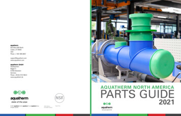
Product GuideFigure 1: Installation Kits1Collector Installation Kit(PN 12034-1 for 1½”; PN 12034-2 for 2”)4Used when more than one row of collectors is to be installed. The kit contains additional hold-down hardware, connector hoses, and adapters. Use one (1) kit for each rowof collectors after the first.Contains the parts needed to fasten a single solar collectorto a supporting surface and make water connections fromone collector to another. Hold-Down Strap is not includedand must be ordered separately. One (1) kit required percollector.25System Installation Kit(PN 12135-1 for 1½”; PN 12135-2 for 2”)Row Spacer Kit(PN 12017-1 for 1½”; PN 12017-2 for 2”)Contains the hardware needed to space around any widthobstruction by connecting appropriate lengths of PVC pipeto the Pipe Adapters at the inlet and outlet headers of thetwo collectors on either side of the obstructions. Use one (1)for each gap between collectors.Includes additional hold-down hardware, connector hoses,and adapters needed to complete water connections fromcollectors to the system feed and return line. One (1) kit required per system.62A Optional Supplemental System Isolation Kit(PN 12033-5) - Permits manual isolation of the solar system from the pool or spa filtration system. Includes a 1½” 2” PVC union ball valve and a 1½” - 2” PVC check valve.Use (1) kit per system.3Add-a-Row Kit(PN 12043-1 for 1½”; PN 12043-2 for 2”)Hold-Down Strap(PN 12033-5) - Required to secure collectors to the mount-Supplemental Outlet Header Clamp AssembliesUsed as supplemental outlet header mounting in conjunction with the Outlet Header Hold-Down Bracket Assembly.Designed for installations that require more flexibility for theoutlet header mounting hardware location, such as barrel tileroofs or installations that require additional mounting hardware to be anchored into rafters or beams.Use up to two (2) per collector.ing surface. Use 54’ roll (PN 10035-1) for rows of up to six(6) collectors with two straps. Also available in 107’ roll forrows up to twelve (12) collectors (PN 10035-2), and bulk1400’ roll (PN 10040).PN 10117-1 / -22PN 101211
Product GuideConnections & HardwareOutlet Header Hold-DownBracket Assembly(PN 10008-1, -2)Double Hole OutletHeader Bracket(PN 50069)Flashing Base,Outlet Header(PN 30340-1)Hold-Down StrapClamp Assembly(PN 10011)Collector Connector Hose(3 3/4” long)(PN 60690-1, -2)Hold-DownStrap Bracket(PN 50006)Stainless SteelHose Clamp(PN 60003-1, -2)System Connector Hose(7” long)(PN 60691-1, -2)Flashing Base,Strap Bracket(PN 30340-2)End Cap(PN 30061-1, -2)Vacuum-ReliefValve(PN 10003-1, -2)Pipe Adapter(High-temperature CPVC)(PN 30089-1, -2)ColleectorInstallation KitSysttemInstallation Kit(PN 120334-1 / -2)(PN 121335-1, -2)Check Valve(PN 60019-2)Row Spacer KitAdd-a-RRow Kit(PN 120117-1, -2)(PN 120443-1, , -2Outlet Header Hold-Down Bracket Assembly1111111130340-1Flashing Base, Outlet Header1111111150006Hold-Down Strap Bracket2222222230340-2Flashing Base, Strap Bracket22------10011Hold-Down Strap Clamp Assembly--44444460003-1, -2Hose Clamp, Stainless Steel4444444430061-1, -2End Cap--11--1110003-1, -2Vacuum Relief Valve--11--1160690-1, -2Collector Connector Hose (3 3/4” long)11--22--60691-1, -2System Connector Hose (7” long)--22--2230089-1, -2Pipe Adapter (high-temperature CPVC)--22442260019-2Check Valve (1½” & 2”)--11----19001Installation Manual--11----19697Owner’s Manual--11----32
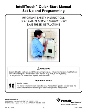
4Figure 2: System Schematic
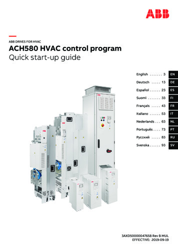
Mounting the CollectorsCollector Layout Overview & Planning for Obstructionsweld while pulling the two plates apart. Lay the collectorover the vent pipe, keeping the vent pipe at least 12inches (30cm) away from a header. It will be easier tocomplete an installation by mounting this panel first andthen working away from it.For obstructions up to 7” (18cm) in diameter, thecollectors can be positioned on either side of the vent.Two 7” (18cm) long System Connector Hoses (PN60691-1 for 1½” or PN 60691-2 for 2”) can be employedOverviewto couple the collectors together for vent pipes or other When mounting the collectors, always make provisions for inlet connections at the bottom header andoutlet connections at the top.obstacles up to 7” (18cm) in diameter. Mark your 51”(128cm) centers wherever the outlet header brackets‘fall’ on the upper chalk line. The outlet headers must be pitched a vertical distance of at least 1/8” per foot (1cm per m) above theFor obstructions over 7” (18cm) in diameter, suchas attic fans and skylights, position collectors on eitherinlet headers to assure uniform flow and proper drainage to prevent freezing.side of the obstruction using a Row Spacer Kit (PN12017-1 for 1½”; PN 12017-2 for 2”) or Header Spacers Plan system location to allow at least 12” (30cm) onall sides of the row(s) of collectors for mounting brackets and piping.(PN 30017-1, 2, 3, 4 for 1½”; 30159-1, 2, 3, 4).Roof obstructions, if present, should now be takeninto account to determine the exact collector location.Collectors can be installed over or around different diameter roof vent pipes or other obstructions. After snapping the top chalk lines but before marking and predrilling for your outlet header brackets, refer to the following instructions:For roof vents up to 2” (50mm) in diameter the col-Using various configurations of hoses and headerlectors can be installed directly over these vents. Locatespacers, this system avoids roof obstructionsthe seam in the panel nearest to where the vent pipe iswhile maximizing the solar collector area. (Phototo come through. Separate by pulling up on top plate,courtesy of Solar Living - Fair Lawn, NJ)and pushing down on the lower plate. Should the ventpipe protrude near a sonic tack weld, it will have to becut apart. Using a sharp utility knife, cut through the52
Mounting the CollectorsStep 1: Install Outlet Header Hold-Down Bracket Assembly1. Determine the position of the last Outlet Header Hold-Down Bracket Assembly for the row of collectors, and mark this point on the roof. The collector outlet headers will be located 1” (25mm) below this mark.2. Using this point, snap a chalk line to the opposite end of the row. Slopethis line down the roof toward the inlet a minimum of 1/8” per foot(1cm per m).3. Using a 1/8” (3mm) drill bit (for 1/4” (6mm) diameter screws), drill a pilothole for the first Outlet Header Hold-Down Bracket Assembly on the firstroof mark.4. Measure up 1” (25mm) on center from the first pilot hole and drill a pilothole for the second screw. Repeat this process all along the chalk linefor the total number of collectors to be installed.5. Inject a generous amount of high quality sealant into each hole and ontothe surrounding roof surface. Attach the Flashing Base & Outlet HeaderHold-Down Bracket Assembly to the roof as shown in Figure 3.FIGURE 3Step 2: Hold-Down Strap Bracket Locations1. Locate the Hold-Down Strap Bracket (PN 50006) locations using Table 1 below. Measure “(A) Distance” down fromthe top Outlet Header Bracket, and snap a chalk line to the opposite end of the row. If using the Optional Supplemental High Wind Area Collector Hold-down Kit, use (A2) Distance from the outlet header for all three top straps2. The “(B) Distance” can be measured after the collectors are installed, and is the same for all collector sizes: 16”(40cm) up from the bottom of the inlet header.Wait to install the Hold-Down Strap Brackets until after collectors are installed, so as not todamage the collectors when you are bringing them to the roof for installation.T ABLE 1 DISTANCE BETWEEN COLLECTOR HEADERS AND STRAPSCollector Panel Size, Feet (m)12 (3.6)10 (3.0)8 (2.4)6 (1.8)4 (1.2)(A) Distance from Outlet Header, Inches (cm)60 (152)48 (122)36 (91)24 (60)-(A2) Distance from Outlet Header, Inches (cm)32 (81)28 (71)20 (51)--(B) Distance from Inlet Header, Inches (cm)16 (40)16 (40)16 (40)16 (40)16 (40)63
Mounting the CollectorsStep 3: Install Connection Hoses on CollectorsMake sure that the header with the serial number label is used for the outlet or top header.The serial number label must face downwards towards the mounting surface.1. Bring the first collector to the roof and slip the proper hoses over both ends of the inlet and outlet headers on thelast return collector.2. Use System Connector Hoses (PN 60691-1 for 1½”; PN 60691-2 for 2”), at the system’s feed and return points(outlet of the last collector and the inlet of the first collector).3. Place a hose clamp between the two indicator ridges on the hose, in order to center it over the sealing groove inthe header. This clamp must face up so as to be accessible for tightening and not rub against the mounting surface.4. Make sure you securely tighten each clamp with a nut driver. If a nut driver is not available, a ‘hex’ wrench orscrewdriver will suffice.The hose clamps must be located between the two indicator ridges on the hose.Do not tighten more than 35-40 inch-pounds!Step 4: Secure Outlet Header Bracket to Collector Connector Hoses1. Position the collector on the roof so that the center of the outlet Connector Hoses are directly beneath the secured Outlet Header HoldDown Brackets.2. Open the clamp that is part of the outlet header bracket, insert connection hose and lightly tighten the clamp around the hose.3. Loosely place another clamp over the open end of the hose beforeinstalling the next collector in the array. Refer to Figure 4.4. Continue to install all the collectors in the array, coupling them sideto side.FIGURE 4Supplemental Mounting HardwareIf using the supplemental Aluminum Header Clamp Assembly,(PN 10117-1 for 1½”; PN 10117-2 for 2”), or GFPP OutletHeader Clamp Assembly, (PN 10121) install after both the OutletHeader Hold-Down Brackets and collectors have been installed.74
Mounting the CollectorsStep 5: Install Hold-Down Strap Brackets & Stainless Steel Strap1. At the lower chalk line previously snapped on the roof, mark locations forthe first row of Hold-Down Strap Brackets 2” (5cm) away from the first andlast collectors and centered between each collector.2. Drill a pilot hole and apply sealant, then mount the Flashing Base andHold-Down Strap Bracket. Slip a Strap Hold-Down Clamp (PN 10011) overthe end of the strap prior to pulling it through (refer to Figure 5).3. Loop approx. 2” of strap through the Outlet Header Bracket and then backthrough the Hold-Down Strap Clamp. Slide the Hold-Down Strap Clamptowards the Hold-Down Strap Bracket. The screw should be tightened securely, but not over-tightened to the point where the clamp is distorted (refer to Figure 5).FIGURE 5For longer arrays it will be easier to start the strapin the middle collectors and work your way out.4. Moving across the row, drill pilot holes at each marked point between collectors, apply sealant, and attached allFlashing Bases and Hold-Down Strap Brackets to the roof.5. Bring the remaining strap end across the collector face, passing through bothslots of the Hold-down Strap Brackets between collectors. Pull strap tautagainst the face of the collectors. Repeat strap termination at opposite end(refer to Figure 6).6. Mark, drill, and mount the remaining Hold-Down Strap(s) by repeating theabove steps at the distance(s) specified in Table 1 in Step 2: Hold-DownStrap Bracket Locations.It is ok to step on the collectors, as long as you stayone foot away from the top and bottom headers.FIGURE 685
Mounting the CollectorsStep 6: Install Vacuum Relief Valve & End Cap1. Install the Vacuum Relief Valve (PN 10003-1 for 1½”; PN 10003-2 for 2”) in theoutlet header of each row.This will be located at the opposite end of the header that is connected to thecollector return line.Vacuum Relief Valve2. Install an End Cap (PN 30061-1 for 1½”; PN 30061-2 for 2”) in the inlet header ofeach row, opposite the end that is connected to the collector inlet pipe.Do not over-tighten hose clamp around VRV or End CapEnd CapInstallation in High Wind AreasIn regions where high winds are prevalent, use the Supplemental High Wind Area Collector Installation Kit, (PN 12035-1for 1½”; PN 12035-2 for 2”) and Supplemental Row/System Kit (PN 12143-1 for 1½”; PN 12143-2 for 2”) in addition tothe standard installation kits (refer to Figure 7). The included bracket assembly’s spring-tension design allows forcollector expansion and contraction, while providing an additional mounting point. Supplemental High Wind Kits alsocontain the required hardware for two additional Hold-down Straps. Use Table 2 below to determine proper springtension length, based on collector size and average air temperature.FIGURE 7High Wind Area Hold-down KitT ABLE 2 SPRING TENSION LENGTHTEMP0158’5”510’5”3045604- 3/4”851151604 3/443/4”4 1/241/2”1301455”54 3/443/4”7710012’4 3/843/8”4- 1/2”4- 1/2”4- 3/8”4- 3/8”NOTE: Bracket not at tension96
System PipingOverviewPiping to and from the collectors should be the same type of plastic piping and fittings approved for use with swimmingpool filters and pumps. It is recommended to always use Schedule 40 PVC pipe and fittings.Whenever there is more than 50 gpm (189 Lpm) required flow rate to the collectors or more than 100’ (30m) of pipingused in a system, install 2” (63mm) piping to and from the collectors. See Table 3 for Pipe Size Based on Flow Rate.T ABLE 3: PIPE SIZE BY SYSTEM FLOW RATEUM FLOW TO PURGGE AIRMINIMUSUPPORT CENTERSHORIZONTALFLOWFOR HORRIZONTALFLOW-UPDOWN FLOW2 FT/S4 FT/S6 FT/SSDR&SCH. 40SCH. 80MINIMUM PIPEFLOW RATE(GPM) SIZE @ 7 FT/SVELOCITY(INCHES)PVC PIPE (FEEET) 06.01763535297.59.010508.030065010008.08.5If a fuel-fired heater or heat pump is installed, it should be located between the solar return line and the return lineto the pool. Although PVC pipe is generally white, black is also available but may be difficult to find locally. If black pipe isdesired for aesthetics, it can always be painted black. Before painting, the PVC pipe must be wiped with cleaner toremove the glossy surface coating. This will ensure that the paint will not flake off prematurely. Use a PVC cutter or a PVC wide-blade saw (not a hacksaw) for cutting pipe. It is important to use both a qualitycleaner/primer and solvent in gluing a PVC joint. Finally, use a cloth while either gluing or painting to keep the job aclean one.Pipe Brackets Piping should also be supported at intervals based on pipe size(see Table 3). Aquatherm Industries Pipe Brackets made fromhigh-strength glass-reinforced polypropylene are available in1½” (PN 30272-1 black; PN 30284-1 white) and 2” (PN 30272-2black; PN 30284-2 white).107
System PipingSystem Piping ConfigurationsThe most common piping configurations use a pressure filter. The pump draws the water from the skimmer and/or amain drain, forcing it through the filter and sending it back to the pool through the return lines. (For other types pleasecontact Aquatherm’s Engineering Department).FIGURE 8FIGURE 9Reverse ReturnDirect ReturnIn a traditional reverse return piping configuration,the feed and return points of each row of collectors will be diagonally opposite each other.In certain situations, it may be desirable toconfigure a system with the feed and return points onthe same side of a row of collectors (see diagram toleft).The Vacuum Relief Valve and End Cap of each rowwill also be diagonally opposite each other (see diagram at right).Though this configuration reduces the total pipe required, and is often more aesthetically-pleasing,proper flow rates are crucial to ensure balanced flowthrough each row.Using a reverse return configuration ensuresbalanced flow across the entire row of collectors.See Table 4 below to determine the maximum number of collectors allowable in a direct return system atvarious flow rates.T ABLE 4: REQUIRED FLOW FOR DIRECT RETURN8’’COLLECTOR IMUM FLOW RATE (0.06 GPM/FT²)------STANDARD FLOW RATE, (0.10 GPM/FT²)666666RECOMMENDED FLOW RATE, (0.15 GPM/FT²)787877MAXIMUM FLOW RATE, (10 GPM PER COLLECTOR)81281088118
System PipingFlow RateIn order to achieve optimum performance from Aquatherm Industriescollectors, the recommended flow rates and number of collectors perrow in Table 5 should be followed.When the system is running, all the collectors should feel uniformly coolto the touch, and there should be no residual air left in the pool returnlines. If collectors feel warm or hot to the touch, or air bubbles in thereturn line persist, chances are that flow through the collectors isinadequate or the system is not properly balanced (refer to the sectionconcerning the Vacuum Relief Valve Test on page 14. A flow meter can be installed in the collector feed line to check the flow rate. If the flow rates are within the limits asshown above in Table 5, the system may not be properly balanced, especially in systems with multiple banks ofcollectors.T ABLE 5: FLOW RATESCOLLECTOR SIZE, FEET:4 X 124 X 104X8STANDARD FLOW RATE PER COLLECTOR, GPM (LPM)5.0 (18.9)4.0 (15.1)3.25 (12.5)MINIMUM FLOW RATE PER COLLECTOR, GPM (LPM)3.0 (11.4)2.5 (9.5)2.5 (9.5)10; 1212; 1212; 14480; 576480; 576480; 576MAXIMUM # COLLECTORS PER ROW, 1½”; 2”MAXIMUM SQUARE FOOTAGE PER ARRAY, 1½”; 2”PRESSURE DROP (PSI @ GPM): 1½” - 0.05 @ 2.5; 0.13 @ 5.0; 0.39 @ 10.0 2” - 0.05 @ 2.5; 0.20 @ 5.0; 0.60 @ 10.0 If the flow rate is below the minimum as shown in the table above, then the pool pump size orpipe size should be increased, or a booster pump installed in some cases.If the flow rate is excessive (more than 10 gpm / 37.9 Lpm) collector), or if the system pressureis greater than 30 psi, a By-pass Check-Valve (PN 60717) should be installed between thecollector feed and return lines above the 3-way valve to prevent problems with the collectorsand connection hoses.If the system has been installed according to this manual, optimum performance conditions will now exist. Systemswith rows of collectors of unequal size, but fitted with balancing valves, may now be adjusted.Open all balancing valves completely and let the system run for several minutes. Any row that is warmer to the touchthan others is currently receiving less flow then it should for optimum performance. Throttle the valve(s) of the other(cooler) row(s) step-by-step, each time waiting for a few minutes, and check the temperature. Once all rows feeluniformly cool, the system is balanced and operates at optimum performance. Should unexpected problems beencountered, the flow rate must be checked out more thoroughly.129
System PipingOptional Isolation ValvesIsolation valves may be installed in the collector piping, so that the poolmay be operated while the collectors are being serviced, or duringfreezing weather. Install a manually operated ball valve in the systemfeed line, and a check valve on the return line. Both valves, available in the Supplemental System Isolation Kit (PN 12033-5) are made to accept either 1½” or 2”PVC pipe. Make sure that the arrow on the check valve is pointing away from the collectors, and that the ball valveand check valve are located close to the control valve and outlet ‘T’, respectively.For further precautions in warm climates where pools are operated year round and periodic freezes can occur, a bypassline (small diameter tubing), can be located above the ball and check valve so as to prevent any accidental trapping ofwater in the collectors by the pool owner. To make sure no water is left in the collectors for servicing or during freezingconditions, remember that the pool pump should be shut off, allowing the collectors to drain naturally, before theoptional isolation valves are used.If the system is installed on a commercial or public pool, local codes mayrequire positive isolation valves in the collector feed and return lines, anda pressure-relief valve in the piping to the collectors.Control SystemsControl TypesAutomatic Control: The performance of a solar pool heater can be maximized with the use if an electronic control andmotorized 3-way valve. When solar energy is available, the control activates the motorized valve, sending waterthrough the collectors for heating (or nocturnal cooling). When the pool reaches the set temperature, or there isinsufficient solar energy available, the valve will turn to bypass the solar system. Refer to the manufacturer’sinstructions included with the automatic control you use.Manual Control: Some systems employ a manual control valve to divert the flow of water to the solar system, thoughthis may reduce the overall heating capacity of the system. Pool water continuously flows through the solar systemwhen the filtration pump is on, but can be diverted manually if the pool becomes too warm or during extended periodsof insufficient solar energy. A manual control system consists of a non-positively sealed 3-way valve in place of themotorized valve.Booster Pump System: In some cases, the existing pool filtration pump may not be able to circulate water at a highenough flow rate to allow for proper collector operation. If so, it may be necessary to replace the filter pump with alarger one, or add a booster pump. An increase in pump size may require an upgraded filter with greater flow ratings.Regardless of control type, the three-way diverter valve used should benon-positively sealed in order for proper system drain back to occur.1310
Checking for OperationsSystem Startup, Testing, and TroubleshootingEach time the solar system cycles on, there are a few things to watch for: Air will initially be purged into the pool. This may last several minutes. The filter pressure will increase slightly and remain elevated when pool water is flowing through the solar system. When the system is running, all the collectors should feel uniformly cool to the touch.Vacuum Relief Valve Test: When the solar system is first turned on, air in the collectors will be expelled into thepool and bubbles will appear. The appearance of bubbles in the pool should stop after a few minutes. If, after a few minutes, bubbles continue to be discharged from pool returns, remove the Vacuum Relief Valve(s)and replace it with an End Cap. If the bubbles discontinue, the issue may be the Vacuum Relief Valve location. If bubbles continue, reverse the End Cap and the Vacuum Relief Valve on the collector array to see if this stops thebubbles in the return lines. If bubbles continue after reversing the VRV and End Cap, relocate the VRV to a position in the inlet piping at aheight of approximately 3/4 of the elevation of the collectors above the pool. Refer to Figure 2.Flow Rate Test Methods:1.Flowmeter: The preferred system test method is flow rate. This is also the easiest and quickest method. Tocheck flow rate, install a flow meter in the inlet line to the collectors (follow installation instructions providedwith the flowmeter).2.Touch Method: With the system running and the sun shining, all collectors of the system should be uniformlycool to the touch, and the system will be operating at optimum performance.3.Temperature Rise Method: An alternate method to test adequate flow is by measuring the temperature riseof pool water through the system. It is important that the temperature rise through the collectors be keptas low as possible in order to deliver the maximum amount of heat to the pool. Use two accuratethermometers - one in the pool water or filtration piping prior to the collectors, and one in the system outletpiping - to measure the temperature rise from solar. Before installing, immerse both thermometers in the pool water for several minutes to compare temperaturereadings. If they are not identical, make a notation of the difference and add or subtract (as appropriate) thisdifference to or from the reading taken while you are testing. Turn the pump on and move the flow switch to the “Manual ON” position to divert pool water through thecollectors. After at least fifteen minutes of flow to collectors, compare the temperature of the pool water withthe water flowing through the outlet piping.On an average sunny day, with the air temperature approximately 70 F (40 C) the water leaving thecollectors should be 1 to 7 F (1 to 4 C) higher than that in the pool. If the water rise is greater thanksthis, insufficient water is flowing through the collectors. This may be caused by a clogged filter,undersized piping, too many elbows in the piping or an inadequate pump.1411
MaintenancePool Service & MaintenanceBackwashing & Adding DE: It is advisable to bypass the solar collectors when either backwashing your filter oradding Diatomaceous Earth (DE). This prevents the possibility of any DE or other debris from passing through the solarsystem as well as any other pool equipment downstream of the filter. When the backwashing cycle and/or the adding ofDE is complete, run the filtration system for 10-15 minutes before returning your solar heating system to operation.Automatic Pool Cleaning Systems: If you have an automatic pool cleaning system with its own pump, there maybe several precautions that you need to take depending on what type of system you have. These precautions preventthe air that is initially purged from the solar system from possibly damaging pool cleaning equipment during the turningon cycle of your solar system. Manual Control: Do not start the flow of water through the solar collectors while the pool cleaning pump is running.Allow the air to be purged from the system and then activate your pool cleaning system. Automatic Systems: If your automatic control system is not equipped with a timed pool cleaner delay cycle, it willbe necessary to run your pool cleaner in the early morning and turn it off before your solar system comes on; or turnit on in the late morning, well after your solar system normally cycles on. If you manually vacuum your pool,bypassing the solar collectors at this time will provide you with full power for better vacuuming performance.Cold Weather Operation & Winterization ProceduresDuring normal operation of the system, when the 3-way valve is in the “bypass collector” position, all water in thecollectors should drain back through the 3-way valve (non-positively sealed) when the filter pump shuts off. If there is anisolation ball valve on the feed line, it should only be closed after the collectors have drained fully. Provided collectorsare drained, there are no further requirements for winterizing the solar collectors. The pool piping should be winterizedas per your normal practice.In some areas, pool owners operate their pools throughout the winter although light freezing conditions may occur.When solar heaters are used on a pool under these conditions, anti-freeze precautions should be taken. In order toprotect the collectors as well as appurtenant components such as End Caps and pipe fittings against unusual or severefreezing conditions, one of the following two procedures should be followed when freezing weather is imminent.1. If isolation valve(s) have been installed, turn circulating system off and allow solar collectors and piping to drain.Close isolation valve(s) if applicable. Switch the solar control to “OFF” or “Solar Disabled”. The pool filtering systemmay then be turned back on. When freezing conditions have passed, open isolation valve(s) and switch the solarcontrol to “AUTO” or “Solar Enabled”.2. If the system can not be drained and isolated, the accepted procedure for avoiding freezing of the pool piping andfiltration system has been to continuously circulate the water. Switch the solar control to the “Manual ON” positionso that water circulates through the collectors. When freezing conditions have passed, switch the solar control to“AUTO” or “Solar Enabled”. This method is not recommended where temperatures may drop severely.1512
Booster Pump System DiagramIn some cases, the pool filtration pump may not be able to circulate water at a high enough flow rate to allow forproper collector operation. If so, it may be necessary to replace the filter pump with a larger one or add a boosterpump. If the pump size is increased, it may also be necessary to upgrade the filter to one with greater flow ratings.For the latest revision of this manual, or to view the complete unabridgedmanual, please visit www.aquathermindustries.com/installAn ISO 9001:2008 Registered ManufacturerAquatherm Industries, Inc.1940 Rutgers University Blvd.Lakewood, New Jersey 08701Phone: 732-905-9002Email: info@aquathermindustries.comPart No. 19001 Rev. 4/15INDUSTRIES,INC. 2015 Aquatherm Industries, Inc.13
cedure for the installation of an Aquatherm Indus-tries Solar Pool Heating System. If the directions are followed correctly and only recommended Aq-uatherm Industries hardware and components are . 60691-1, -2 System Connector Hose (7" long) -- 2 2 -- 2 2 30089-1, -2 Pipe Adapter (high-temperature CPVC) - - 224422