Transcription
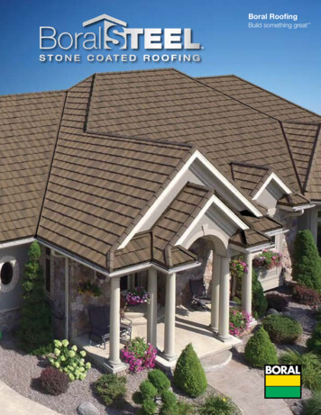
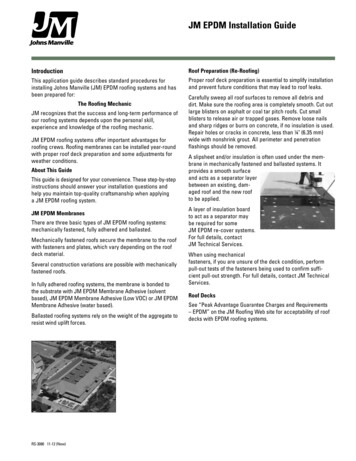
Gerard Installation ManualShingle ProfilesGranite Ridge ShingleGuardian ShingleMarch 2017
Shingle Installation ManualThis Installation Manual is designed as an instructional tool to clearly depict to the contractor, installer,distributor and architect, recommended installation techniques and procedures to confidently estimate andinstall a Granite Ridge and Guardian Shingle roofing system by Gerard Roofing Technologies.This manual depicts generally practiced application techniques only, which should not be substituted for local building code specifications. Gerard Roofing Technologies carries product app roval reports for most building code agencies in North America which should be referenced forspecific local requirements. See Gerard’s website for further information.These methods have been developed by Gerard Roofing as proven acceptable and tested methods ofinstalling Gerard Stone Coated Steel Roofing. Gerard Roofing does not construe that these are the onlymethods but again are the tried and true proven techniques that are currently practiced by the majority oftrained installers.This manual emphasizes common roofing practices in use today. If application techniques vary from thoseillustrated in this manual or if using this manual for applications not covered, please consult the technicaldepartment at 1-800-237-6637.As Gerard Roofing Technologies have no control over the installation techniques used, no warranty can bemade relating to the installation of Gerard products.Product Approval Reports for various areas are available which should be analyzed for additional procedures after careful review of this manual.A careful study of this manual will give a full comprehension of a Granite Ridge and Guardian Shingle roofinstallation.Gerard Roofing assumes no liability for either incorrect installation of its products or personal injury that may occur as a result of installing such products. The installation methods demonstratedin these materials are not the only ways to install Gerard products, but have been developed as areference guide using acceptable, tested and proven methods for the standard installation of Gerard products. Contractors and installers should at all times use their professional judgment, andmodify and tailor such methods where appropriate or necessary to suit each specific installationor any applicable local building codes or ordinances. Due to the fact that Gerard has no controlover the actual installation techniques used, no warranty is expressed or implied relating to installation of the product. Gerard’s liability with respect to Gerard products is limited exclusively to itsstandard written limited lifetime warranty.Please Note: It is the responsibility of the installer to adhere to local building codes.2Gerard Roofing TM
Shingle Installation ManualTable of ContentsGerard Shingle Description4Tool Requirements5Materials6-8Estimating9Roof Preparation10Rake/Roof-To-Wall and Felt11Valley12Shingle Installation13Roof-To-Wall and Valley Cap Detail14Hip and Ridge15Riglet Installation16Pipe Jack Installation17Master Flash - Optional18Touch Up and Completion193Gerard Roofing TM
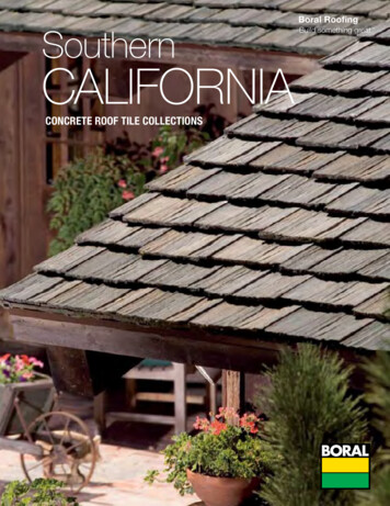
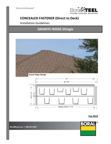
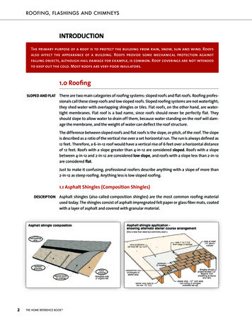
Shingle Installation ManualGerard Shingle DescriptionGuardian Shingle15 5/8”13 11/16”Granite Ridge Shingle15 5/8”13 11/16”ActualExposureCoverageAverage weight per shingleAverage weight per squareRoof Pitch46 1/6” x 15 5/8”44” x 13 11/16”24 shingles per square5 lbs120 lbs4:12 minimum to vertical4Gerard Roofing TM
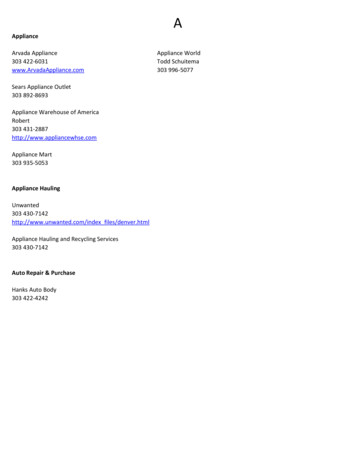
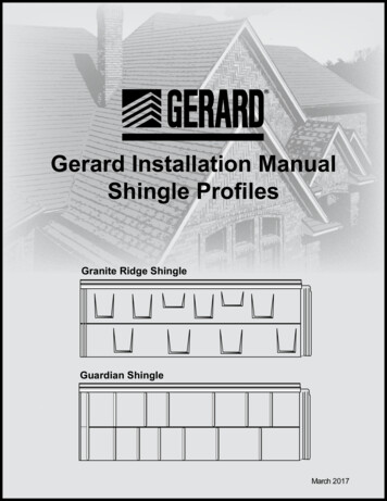
Shingle Installation ManualTool RequirementsList of Tools Required:- Standard claw hammer- 50’ or 100’ tape measure- Screw drivers (optional power drive)- Utility knife (when re-roofing over composition shingle)- Tin snips- Caulking gun- Chalk line- One pair of needle-nose pliersGerard Tile Cutter- creates neater, straighter cutsReplacement Handle GripReplacement Top BladeReplacement Bottom BladeThe Tru-Cut Shear is reversible for left-handed or right-handed use.Assembly shown here is for right-handed use. Simply reverse assemblyfor left-handed use.5Gerard Roofing TM
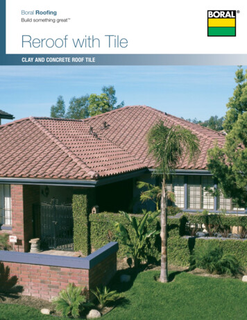
Shingle Installation ManualMaterialsGranite Ridge ShingleStone Coated24 pcs. / sq.Guardian ShingleStone Coated24 pcs. / sq.Valley CapStone Coated120” LengthChar Filter Foam (Under Valley Cap)Non-Stone Coated3/4” x 4-1/2“ x 118” LengthValleyNon-Stone Coated120” LengthRigletNon-Stone Coated120” LengthRake/Roof to WallNon-Stone Coated120” Length6Gerard Roofing TM
Shingle Installation ManualMaterialsZ-Bar Attachment (Roof to Wall)Stone Coated120” (10 ft.) LengthsRake/Roof to Wall Pce.Rake CoverStone Coated120” LengthRake/Roof to Wall Pce.Starter StripStone Coated120” Length110 Head MetalStone Coated120” LengthHip and Ridge CapStone Coated14” LengthPipe Jack Tray (Cut centre hole on site)Non-Stone Coated14” x 14”Pipe Jack Flashing:Part no: See Inside SalesCoated or Non-coated7Gerard Roofing TM
Shingle Installation ManualMaterialsGuardian ShingleGranite Ridge Shingle30 # FeltPanel Fasteners:(Installing contractor responsible to check local code requirements for type of fastener).Ring Shank Roofing Nails:1-1/4” minimumSufficient length to penetrate sheathing per code (min. of 1/2”)Screws:#8 x 1-1/4”(Higher wind load regions)* In high wind regions refer to local building codes and manufacturer applicableproduct evaluation reports.Stitch Screw for Valley Cap Only:#8 x 1/2”E Z Vent for Shingles:Ventilation Option for high wind regionsSealantNP1 or equalProfessional thermoplastic sealantSuper flexibleScellant thermoplastique profesional Super flexibleFinishing Kit / Touch UpComprises of 8 oz. squeeze bottle of base and 3 lbs. of color stone chosen.8Gerard Roofing TM
Shingle Installation ManualEstimatingHow to Determine How Much Material You Will NeedQuick Step Method, USA Standard(approximate)1. Determine roof square foot feet without waste.2. Add linear feet of hips and valleys. Multiply by 2.3. Add totals from steps 1 and 2.4. Multiply total by 1.03. This yields roof square feet including waste.5. Divide total from step 4 by 100. This yields roof squares. Gerard Shingle is 24 panels persquare.Hip Length 21’Rafter Length 18’Overall Fascia Length 50’1) 50 X 36 1800 s/f w/o waste2) Hip x 4 84 x 2 168 linear feet3) 168 1800 19684) 1968 x 1.03 20275) 2027 100 20.27 sqs9Gerard Roofing TM
Shingle Installation ManualRoof PreparationGerard Shingle can be installed over low profilecomposition shingle or over solid sheathing witha minimum type 30 felt underlayment. If youchoose to re-roof over lower profile compositionshingles the procedures are as follows:1. Cut back existing shingles flush with theperimeter of the roof.2. Remove existing drip edge.3. Remove hip and ridge cap.4. Cover the entire roof with a minimum of #30felt. Lay one additional layer of 30 lb. felt up thevalley. If you live in an area where ice dammingoccurs use ice and water shield. At the valleys,weave the opposing courses of underlayment.Install underlayment on top of the starter strip.Starter StripUnderlaymentNailStarterStripCut back existing shinglesFascia10Gerard Roofing TM
Shingle Installation ManualRake/Roof-To-Wall and FeltUnderlaymentRAKE COVERFASTEN RAKE COVERHERE & AS NEEDEDRAKE ORGABLE ENDthe rake roof to wall (approx 3”). The rake covershould be notched at the top flange in order toachieve side lap 1 - 1 1/2” is sufficient.5. Use a chalk line when installing the starterstrip. Do not depend on the roof edge to bestraight or square. Nail starter strip every 16”along the fascia line. Reminder - underlaymentinstalled on top of starter strip.7. Ensure that the bottom end of the rake roofto wall overlaps the top flange of the starterstrip and extends to or slightly beyond the loweredge of the starter strip. Place sealant betweenthe lower edge of the rake roof to wall and thestarter strip.6. Install the uncoated rake roof to wall up thegable or rake, fastening it where shown. It issometimes easier to assemble the rake coveron to the rake roof to wall before installing.When done this way, shorten the first (bottompiece) of rake cover in order to prevent all theends from lining up. Head lap is necessary for11Gerard Roofing TM
Shingle Installation ManualValleyEnsure that the full width of the valley overlaps the top flange of the starter strip and extends slightlybeyond the lower edge of the starter strip. Place sealant between the lower edge of the valley andthe starter strip. Trim lower edge of the valley as needed.Fasten and seal in outer channelPlace sealant12Gerard Roofing TM
Shingle Installation ManualShingle Installation8. At the eave and starting from left to right,begin installing the Gerard Shingles. Take careto interlock the nose end of the shingle with thenose end of the Starter Strip. Nail the first courseusing seven nails per shingle along the nailingstrip provided at the back of the shingle.9. At the bottom of all rake to wall and valley runs clip and fold under the nose of theshingle to allow for drainage. The drainage opening should reveal the full width of the rake roofto wall or valley. This is only done on the bottomcourse. The same procedure is done at the bottom of a valley to the raised “V”. (see diagrampage 11).ShingleStarterStripFascia10. When installing any panel except for theDiagram Staggered for clarificationthe first one in each course, it is very importantto do the following: After positioning the panelon the roof and making sure the Pittsburgh lockShingle nailing patternUnderlaymentis completely secure, place one hand on the leftside of the shingle just below the center LEFTstep and with the other hand pull up on the topSideleft corner of the same shingle and bend it up toLapat least 45 degrees. Then push the shingle backdown, double check the Pittsburgh lock and fasten the panel in the manner specified. This bending procedure will ensure that all of the side lapFasciaseams will remain tightly closed. Ensure the integrity of the side lap before fastening the sInstalled left to righthingle. If the side lap does not close tightly,hand work the shingle until it does close tightly.11. On all gable, roof to wall, and valley panels,snip off the top corner of the nail strip to 45 (gable panels would be snipped on the gableside - valley and roof to wall panels snippedon the cut side). At the bottom of these sameshingles, make a “v” shaped notch on thebottom of the Pittsburgh lock 1” from the cutedge.Notch12. When installing Guardian or Granite Ridgepanels, it is very important to install the panelsin uniformly straight course. Always be sureto apply each panel with the Pittsburgh lockscompletely connected. Not doing so couldallow panels to become disconnected fromeach other and pop up, creating a problem.13NotchGerard Roofing TM
Shingle Installation ManualRoof-To-Wall and Valley Cap DetailBuilder InstallBuilder Ined Z-Barstalled Z-BarShingle110 Head MetalZ-Bar AttachmentRake/Roof-To-WallRake/Roof-to-Wall110 Head Metal13. Chimneys, skylights and roof to wall areflashed using the rake/roof to wall accessoryalong with the Z-bar attachment. The Z-barattachment is snapped over the top of the Rake/Roof to Wall Accessory Metal and insertedbehind builder installed Z-bar. If there is nothing to slip behind, it becomes necessary to surface fasten and seal. Number and type of fasteners will vary with existing structural conditions.14. Valley Cap along with Char Filter Foam isplaced over the Gerard valley concealing themitered valley cuts and screwed every shingle course along the length of the valley cut toshingles with a #8 corrosion resistant screw.Take care not to penetrate the valley metal.Rake/Roof-to-Wall110 Head MetalValley Capwith CharFilter Foamunder cap.ScrewChipped and CaulkedFasciaover the top of the shingles laid in a bead ofcaulk. If there is nothing to slip behind, it becomes necessary to surface fasten and seal.Number and type of fasteners will vary withexisting structural conditions.15. Install 110 Head Metal at front of thehorizontal wall protrusion by putting one sidebehind builder installed Z-bar and other side14Gerard Roofing TM
Shingle Installation ManualHip and RidgeRake/Roof to Wall Accessory Metal16. The shingles above the eave course areinstalled by interlocking the nose end of theshingle with the back end (Pittsburgh lock) ofthe shingle of the preceding course concealingthe nailing strip.ShingleRake Roof To WallStarter Strip17. At the rake or gable end cut the shingles tofit and insert the cut edge into the rake/roof towall.Notch area at bottomof gable or rake andfold under to allow fordrainage.18. Hip and Ridge shingles are mitered to fitnailed and covered using the Gerard Hip andRidge accessory.19. Before installing Hip and Ridge cap, placea strip of 5 to 6 inch wide Peel-N-Stick (hightemperature) atop the cut hip and ridge shingles.Ridge CapNOTE: Ensure Peel-N-Stick not exposedafter cap installation.Optional Non-Vented Hip DetailScrews - Seal and ChipHip CapMitre CutOptional Hip Detail:Left side panel cuts off at hip intersectionwith the right side panel overlapping overthe hip intersection and left panel byapproximately 2 inches.Note:This detail can also be used for “non-vented”ridge.Screws - Seal and Chip15Gerard Roofing TM
Shingle Installation ManualRiglet InstallationRiglet Set in a bead of NP1 or equal or butyl tape.Fascia Starter StripApply a 1-1/2”, corrosion resistant hex headscrew directly beneath the mid shelf of theshingle and approximately 3” to the right of theleft side of the shingle.This screw is to be ofsufficient length to pass completely throughthe roof sheathing. Do not over tighten or penetrate the overlapped shingle. Make absolutelycertain you have followed the procedure outlined on page 18 - Note 24.20. The Gerard Riglet is available for use withinstallations involving an offset at the eave. TheRiglet is aligned with the offset, set in bed ofcaulk and nailed on the back apron every sixinches. The shingles are then installed on themain roof interlocking with the nose end of theriglet and laying over the top of the shingle below.21. If you have difficulty closing some sidelaps, the following procedure is acceptable:16Gerard Roofing TM
Shingle Installation ManualPipe Jack Installation22.SealantPipe JackPipe Jack TrayWeep-Hole Notch22. Pipe Penetrations:Pipe Jack Tray interlocks with lowerPittsburgh lock.Pipe Jack isis placed overthe pipe anddown onto the PipeJack Tray. Provide weep holesto protect against any future moisture thatmay enter in or around the pipe penetration. A weep holeis created by making t wo vertical cuts at the shingle nose approximately 1” apart. Fold the 1” tab back under the shingle. Seal where indicated.Sealant - Seal and Chip17Gerard Roofing TM
Shingle Installation ManualMaster Flash - OptionEasy 5-Step Installation Masterflash can be installed on-site quicklyand easily, usually under 10 minutes. One piece construction makes Masterflasheasy to handle. Bendable base forms seal with any contour,surface irregularities or roof pitch. Seals tightly and dependably with silicone sealant to eliminate costly call-backs. Pipe opening is easily customized with a sharpknife or scissors for any application. Fix flashing to pipe with stainless steel hoseclamp where snow load conditions exist.1.2.1. Select and TrimChoose appropriate Masterflash with opening atleast 20% smaller than pipe diameter. If necessarytrim opening to 20% smaller than pipe diameter.2. SlideSlide Masterflash down over pipe. (A non-petro leum based lubricant will ease installation.)3.3. FormPress Masterflash down, bending it to conformto roof profile or roof irregularities. A blunt tool willhelp press flashing into tight roof angles.4. SealApply sealant (NP1 or equal) between base and roof.4.5. FastenUse fasteners to complete sealing.Note:For further protection it is recommended toinstall Pipe Jack Tray per details page 17of Pipe Jack installation. Ensure sealingaround roof pipe and Pipe Jack Trayprior to installing cover panel andMasterflash.5.18Gerard Roofing TM
Shingle Installation ManualTouch Up and Completion23. Inspect the roof and touch-up all exposedscrews using the provided touch-up kit. Removeall debris from roof and job-site.24. Acceptable Repair OptionSealantScrewSide LapCorrosion Resistant ScrewMinimum 1 1/2” #8Apply small bead of sealant between panelsat side lap. Ensure sealant is not exposed outside of sidelap.Draw panels togetherDo not over-tighten the screw fastener19Gerard Roofing TM
Gerard Roofing Technologies TM955 Co lu mb ia S treet Brea, California 1-800-23ROOFS1632 Third Street, Leesburg, Forida 1-866-919-76631100 Ch ase Ro ad , S uite 100 Mesquite, Texas 1-866-295-90161115 Eri e S treet, Kansas City, Missouri 1-800-444-4503E-mail: gerardusa@gerardusa.comWebsite: www.GerardUSA.comPlease Note: It is the responsibility of the installer to check the website for any updatesor changes in the application of this product(s).
Shingle Installation Manual Gerard Roofing TM 4 Actual Exposure Coverage Average weight per shingle Average weight per square 46 1/6" x 15 5/8" 44" x 13 11/16"