Transcription
User ManualOff Grid Solar InverterSPF 3000TL LVM-ESVersion: 1.0
Table Of ContentsInformation on this Manual. 1Validity .1Scope .1Target Group .1Safety Instructions .1Introduction . 2Features .2Product Overview .3Installation . 4Unpacking and Inspection .4Battery Connection .5AC Input/Output Connection .9PV Connection . 10Communication Connection . 12Dry Contact Signal . 12Operation . 13Power ON/OFF . 13Operation and Display Panel . 13LCD Display Icons . 14LCD Setting . 16Display Information . 21Operating Mode Description . 22Parallel Installation Guide . 23Parallel Board Installation . 23Parallel Operation in Single Phase. 26Parallel Operation in Three Phase . 29Parallel Operation in Split Phase . 32LCD Setting and Display. 34Fault Reference Code . 37Warning Indicator . 38Battery Equalization . 39Specifications . 40Trouble Shooting . 43
Information on this ManualValidityThis manual is valid for the following devices:SPF 3000TL LVM-ESScopeThis manual describes the assembly, installation, operation and troubleshooting of this unit. Please readthis manual carefully before installations and operations.Target GroupThis document is intended for qualified persons and end users. Tasks that do not require any particularqualification can also be performed by end users. Qualified persons must have the following skills:Knowledge of how an inverter works and is operatedTraining in how to deal with the dangers and risks associated with installing and using electricaldevices and installationsTraining in the installation and commissioning of electrical devices and installationsKnowledge of the applicable standards and directivesKnowledge of and compliance with this document and all safety informationSafety InstructionsWARNING: This chapter contains important safety and operating instructions.Read and keep this manual for future se be clear which kind of battery system you want, lithium battery system or lead-acid battery system, ifyou choose the wrong system, energy storage system can’t work normally.Before using the unit, read all instructions and cautionary marking on the unit, the batteries and allappropriate sections of this manual. The company has the right not to quality assurance, if not according tothe instructions of this manual for installation and cause equipment damage.All the operation and connection please professional electrical or mechanical engineer.All the electrical installation must comply with the local electrical safety standards.When install PV modules in the daytime, installer should cover the PV modules by opaque materials,otherwise it will be dangerous as high terminal voltage of modules in the sunshine.CAUTION-To reduce risk of injury, charge only deep-cycle lead-acid type rechargeable batteries andlithium batteries. Other types of batteries may burst, causing personal injury and damage.Do not disassemble the unit. Take it to a qualified service center when service or repair is required.Incorrect re-assembly may result in a risk of electric shock or fire.To reduce risk of electric shock, disconnect all wirings before attempting any maintenance or cleaning.Turning off the unit will not reduce this risk.NEVER charge a frozen battery.For optimum operation of this inverter, please follow required spec to select appropriate cable size. It’s veryimportant to correctly operate this inverter.Be very cautious when working with metal tools on or around batteries. A potential risk exists to drop a toolto spark or short circuit batteries or other electrical parts and could cause an explosion.Please strictly follow installation procedure when you want to disconnect AC or DC terminals. Please refer toINSTALLATION section of this manual for the details.GROUNDING INSTRUCTIONS -This inverter should be connected to a permanent grounded wiring system.Be sure to comply with local requirements and regulation to install this inverter.NEVER cause AC output and DC input short circuited. Do NOT connect to the mains when DC input shortcircuits.Make sure the inverter is completely assembled, before the operation.1
IntroductionHybrid Power SystemThis is a multifunctional off grid solar inverter, integrated with a MPPT solar charge controller, a highfrequency pure sine wave inverter and a UPS function module in one machine, which is perfect for off gridbackup power and self-consumption applications. This inverter can work with or without batteries.The whole system also need other devices to achieve complete running such as PV modules, generator, orutility grid. Please consult with your system integrator for other possible system architectures depending onyour requirements. The WiFi / GPRS module is a plug-and-play monitoring device to be installed on theinverter. With this device, users can monitor the status of the PV system from the mobile phone or from thewebsite anytime anywhere.FeaturesRated power 3KW, power factor 1MPPT ranges 120V 250V, 250VocHigh frequency inverter with small size and light weightPure sine wave AC outputSolar and utility grid can power loads at the same timeWith CAN/RS485 for BMS communicationWith the ability to work without batteryParallel operation up to 6 unit (only with battery connected)WIFI/ GPRS remote monitoring (optional)2
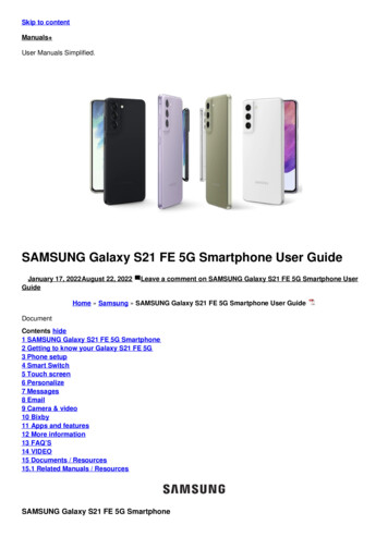
Product Overview1. LCD display2. Status indicator3. Charging indicator4. Fault indicator5. Function buttons6. AC input7. WiFi/GPRS communication port8. USB communication port9. CAN communication Port10. RS485 communication Port11. Dry contact12. PV input13. Power on/off switch14. Battery input15. Parallel communication ports16. Current sharing ports17. AC output18. Circuit breaker3
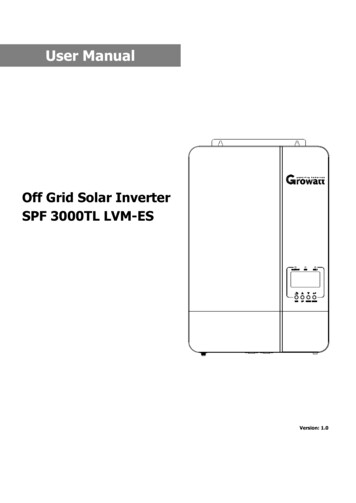
InstallationUnpacking and InspectionBefore installation, please inspect the unit. Be sure that nothing inside the package is damaged. You shouldhave received the following items in the package:The unit x 1User manual x 1Communication cable x 1Software CD x 1Current sharing cable x 1Parallel communication cable x 1PreparationBefore connecting all wiring, please take off bottom cover by removing two screws as shown below.Mounting the UnitConsider the following points before selecting where to install:Do not mount the inverter on flammable construction materials.Mount on a solid surfaceInstall this inverter at eye level in order to allow the LCD displayto be read at all times.The ambient temperature should be between 0 C and 55 C toensure optimal operation.The recommended installation position is to be adhered to thewall vertically.Be sure to keep other objects and surfaces as shown in the rightdiagram to guarantee sufficient heat dissipation and to haveenough space for removing wires.SUITABLE FOR MOUNTING ON CONCRETE OROTHER NON-COMBUSTIBLE SURFACE ONLY.Install the unit by screwing three screws. It’s recommended to use M4 or M5 screws.4
Battery ConnectionLead-acid Battery ConnectionUser can choose proper capacity lead acid battery with a nominal voltage at 48V. Also, you need to choosebattery type as “AGM(default) or FLD”CAUTION: For safety operation and regulation compliance, it’s requested to install a separate DC over-currentprotector or disconnect device between battery and inverter. It may not be requested to have a disconnectdevice in some applications, however, it’s still requested to have over-current protection installed. Please referto typical amperage in below table as required fuse or breaker size.Ring terminal:WARNING! All wiring must be performed by a qualified person.WARNING! It's very important for system safety and efficient operation to useappropriate cable for battery connection. To reduce risk of injury, please use theproper recommended cable and terminal size as below.Recommended battery cable and terminal size:ModelWire SizeTorque valueSPF 3000TL LVM-ES1 * 4 AWG2-3 NmNote: For lead acid battery, the recommended charge current is 0.2C(C battery capacity)Please follow below steps to implement battery connection:1. Assemble battery ring terminal based on recommended battery cable and terminal size.2. Connect all battery packs as units requires. It’s suggested to connect at least 200Ah capacity battery forSPF 3000 ES LV.3. Insert the ring terminal of battery cable flatly into battery connector of inverter and make sure the bolts aretightened with torque of 2Nm. Make sure polarity at both the battery and the inverter/charge is correctlyconnected and ring terminals are tightly screwed to the battery terminals.WARNING: Shock HazardInstallation must be performed with care due to high battery voltage in series.CAUTION!! Do not place anything between the flat part of the inverter terminal and the ringterminal. Otherwise, overheating may occur.CAUTION!! Do not apply anti-oxidant substance on the terminals before terminals areconnected tightly.CAUTION!! Before making the final DC connection or closing DC breaker/disconnector, be surepositive ( ) must be connected to positive ( ) and negative (-) must be connected to negative(-).5
Lithium Battery ConnectionIf choosing lithium battery for SPF 3000TL LVM-ES, you are allowed to use the lithium battery only which we haveconfigured. There're two connectors on the lithium battery, RJ45 port of BMS and power cable.Please follow below steps to implement lithium battery connection:1. Assemble battery ring terminal based on recommended battery cable and terminal size (same as Lead acid, seesection Lead-acid Battery connection for details) .2. Insert the ring terminal of battery cable flatly into battery connector of inverter and make sure the bolts aretightened with torque of 2-3Nm. Make sure polarity at both the battery and the inverter/charge is correctly connectedand ring terminals are tightly screwed to the battery terminals.3. Connect the end of RJ45 of battery to BMS communication port(RS485 or CAN) of inverter.4. The other end of RJ45 insert to battery communication port(RS485 or CAN).Note: If choosing lithium battery, make sure to connect the BMS communication cable between the battery and theinverter. You need to choose battery type as “lithium battery”.Lithium battery communication and settingIn order to communicate with battery BMS, you should set the battery type to “LI” in Program 5. Then the LCD willswitch to Program 36, which is to set the protocol type. There are several protocols in the inverter. Please getinstruction from Growatt to choose which protocol to match the BMS.1. Connect the end of RJ45 of battery to BMS communication port of inverterMake sure the lithium battery BMS port connects to the inverter is Pin to Pin, the inverter BMS port pin assignmentshown as below:6Pin numberRS485 portCAN -8----
LCD settingTo connect battery BMS, need to set the battery type as “LI” in Program 05.After set “LI” in Program 05, it will switch to Program 36 to choose communication protocol. You can choose RS485communication protocol which is from L01 to L50, and you can also choose CAN communication protocol which isfrom L51 to L99.Note: You can only use one communication type RS485 or CAN in a time.AGM (default)FloodedLithium (only suitable when communicated with BMS)User-Defined05Battery typeIf “User-Defined” is selected, battery charge voltage and low DCcut-off voltage can be set up in program 19, 20 and 21.User-Defined 2(suitable when lithium battery without BMScommunication)If “User-Defined 2” is selected, battery charge voltage and low DCcut-off voltage can be set up in program 19, 20 and 21. It isrecommended to set to the same voltage in program 19 and20(full charging voltage point of lithium battery). The inverter willstop charging when the battery voltage reaches this setting.Protocol 1Protocol 2RS485Communication protocol.Protocol 5036Protocol 51Protocol 52CANCommunication protocol.Protocol 997
Note: When the battery type set to Li, the setting option 12, 13, 21 will change to display percent.Note: When the battery type set as “LI”, the Maximum charge current can't be modified by the user. When thecommunication fail, the inverter will cut off output.12Setting SOC point back to utilitysource when selecting “SBUpriority” or “Solar first” in programDefault 50%, 10% 50% Settable0113Setting SOC point back to batterymode when selecting “SBUpriority” or “Solar first” in programDefault 95%, 30% 100% Settable0121Low DC cut-off SOCIf “LI” is selected in program 5,this program can be set upDefault 20%, 5% 30% SettableNote: Any questions about communicating with BMS, please consult with Growatt.Communicating with battery BMS in parallel systemIf need to use communicate with BMS in a parallel system, an external RS485/CAN HUB is needed to converge thecommunication cables from the parallel inverters to lithium battery.RS485/CAN Hub:Two inverters in parallel:8
Six inverters in parallel:Note: The above diagrams described the parallel system communicate with lithium battery in CAN communicationtype, and it is the same to the RS485 communication type. Only need to change to "RS485" port if you use RS485for communication.Note:The above diagrams show the communication wiring of 2 units and 6 units parallel using. For parallel operationwith 3, 4, or 5 units, the communication wiring is similar.AC Input/Output ConnectionCAUTION!! Before connecting to AC input power source, please install a separate AC breaker betweeninverter and AC input power source. This will ensure the inverter can be securely disconnected duringmaintenance and fully protected from over current of AC input. The recommended spec of AC breaker is 40Afor SPF 3000TL LVM-ES.CAUTION!! There are two terminal blocks with “IN” and “OUT” markings. Please do NOT mis-connect inputand output connectors.WARNING! All wiring must be performed by a qualified personnel.WARNING! It’s very important for system safety and efficient operation to use appropriate cable for AC inputconnection. To reduce risk of injury, please use the proper recommended cable size as below.Suggested cable requirement for AC wiresModelGaugeTorque ValueSPF 3000TL LVM-ES1 * 8 AWG1.2-1.6 NmPlease follow below steps to implement AC input/output connection:1. Before making AC input/output connection, be sure to open DC protector or disconnector first.2. Remove insulation sleeve 10mm for six conductors. And shorten phase L and neutral conductor N 3 mm.3. Insert AC input wires according to polarities indicated on terminal block and tighten the terminal screws. Besure to connect PE protective conductorfirst. Ground (yellow-green)L LINE (brown or black)N Neutral (blue)9
WARNING:Be sure that AC power source is disconnected before attempting to hardwire it to the unit.4. Then, insert AC output wires according to polarities indicated on terminal block and tighten terminal screws.Be sure to connect PE protective conductorfirst. Ground (yellow-green)L LINE (brown or black)N Neutral (blue)5. Make sure the wires are securely connected.CAUTION: ImportantBe sure to connect AC wires with correct polarity. If L and N wires are connected reversely, it may causeutility short-circuited when these inverters are worked in parallel operation.CAUTION: Appliances such as air conditioner are required at least 2 3 minutes to restart because it’srequired to have enough time to balance refrigerant gas inside of circuits. If a power shortage occurs andrecovers in a short time, it will cause damage to your connected appliances. To prevent this kind of damage,please check with manufacturer of air conditioner that if it’s equipped with time-delay function beforeinstallation. Otherwise, this off grid solar inverter will trig overload fault and cut off output to protect yourappliance but sometimes it still causes internal damage to the air conditioner.PV ConnectionCAUTION: Before connecting to PV modules, please install separately a DC circuit breaker between inverterand PV modules.WARNING! All wiring must be performed by a qualified personnel.WARNING! It’ very important for system safety and efficient operation to use appropriate cable for PV moduleconnection. To reduce risk of injury, please use the proper recommended cable size as below.ModelSPF 3000TL LVM-ES10Wire Size1 * 12 AWGTorque value1.2-1.6 Nm
PV Module Selection:When selecting proper PV modules, please be sure to consider below parameters:1. Open circuit Voltage (Voc) of PV modules not exceeds max. PV array open circuit voltage of inverter.2. Open circuit Voltage (Voc) of PV modules should be higher than min. battery voltage.INVERTER MODELSPF 3000TL LVM-ESMax. PV Array Open Circuit VoltagePV Array MPPT Voltage Range250Vdc120Vdc 250VdcPlease follow below steps to implement PV module connection:1. Remove insulation sleeve 10 mm for positive and negative conductors.2. Check correct polarity of connection cable from PV modules and PV input connectors. Then, connect positivepole ( ) of connection cable to positive pole ( ) of PV input connector. Connect negative pole (-) of connectioncable to negative pole (-) of PV input connector.3. Make sure the wires are securely connected.Final AssemblyAfter connecting all wiring, please put bottom cover back by screwingtwo screws as shown below.11
Communication ConnectionPlease use supplied communication cable to connect to inverter and PC. Insert bundled CD into a computer andfollow on-screen instruction to install the monitoring software. For the detailed software operation, pleasecheck user manual of software inside of CD.Dry Contact SignalThere is one dry contact(3A/250VAC) available on the rear panel. It could be used to deliver signal to externaldevice when battery voltage reaches warning level.Dry contact port:Unit StatusConditionPower OffNC & CNO & CUnit is off and no output is poweredCloseOpenOutput is powered from UtilityCloseOpenOpenCloseCloseOpenBattery voltage (SOC) Settingvalue in Program 12OpenCloseBattery voltage (SOC) Settingvalue in Program 13 or batterycharging reaches floating stageCloseOpenBattery voltage (SOC) Low DCwarning voltage(SOC)Program 01 setas Utility firstBattery voltage(SOC) Settingvalue in Program 13 or batteryPower Oncharging reaches floating stageOutput ispowered fromBattery or SolarProgram 01 isset as SBU orSolar first12
OperationPower ON/OFFOnce the unit has been properly installed and the batteries are connected well, simply press On/Off switch(located on the button of the case) to turn on the unit.Operation and Display PanelThe operation and display panel, shown in below chart, is on the front panel of the inverter. It includesthree indicators, four function keys and a LCD display, indicating the operating status and input/outputpower information.1. LCD display2. Status indicator3. Charging indicator4. Fault indicator5. Function buttonsLED IndicatorLED IndicatorGreenGreenRedMessagesSolid OnOutput is powered by utility in Line mode.FlashingOutput is powered by battery or PV in battery mode.Solid OnBattery is fully charged.FlashingBattery is charging.Solid OnFault occurs in the inverter.FlashingWarning condition occurs in the inverter.Function ButtonsButtonDescriptionESCTo exit setting modeUPTo go to previous selectionDOWNTo go to next selectionENTERTo confirm the selection in setting mode or enter setting mode13
LCD Display IconsIconDescriptionAC Input InformationAC input iconIndicate AC input power, AC input voltage, AC input frequency, AC inputcurrentIndicate AC power loads in bypassPV Input InformationPV input iconIndicate PV power, PV voltage, PV current, etcOutput InformationInverter iconIndicate ency,inverterLoad InformationLoad iconIndicate power of load, power percentage of loadIndicate overload happenedIndicate short circuit happenedBattery InformationIndicate battery level by 0-24%, 25-49%, 50-74% and 75-100% in batterymode and charging status in line mode.Indicate battery voltage, battery percentage, battery currentIndicate SLA batteryIndicate lithium batteryIndicate charging source priority: solar first, solar and utility, or only solarOther InformationIndicate output source priority: solar first, utility first, SBU mode or SUB modeIndicate warning code or fault codeIndicate a warning or a fault is happeningIndicate it’s during setting valuesIndicate the alarm is disabled14
In AC mode, battery icon will present Battery Charging StatusStatusBattery voltage 2V/cellConstant Current2 2.083V/cellmode / ConstantVoltage mode2.083 2.167V/cell 2.167 V/cellFloating mode. Batteries are fully charged.LCD Display4 bars will flash in turns.Bottom bar will be on and the other three barswill flash in turns.Bottom two bars will be on and the other two barswill flash in turns.Bottom three bars will be on and the topbar will flash.4 bars will be on.In battery mode, battery icon will present Battery CapacityLoad PercentageBattery VoltageLCD Display 1.717V/cell1.717V/cell 1.8V/cellLoad 50%1.8 1.883V/cell 1.883 V/cell 1.817V/cell1.817V/cell 1.9V/cell50% Load 20%1.9 1.983V/cell 1.983 1.867V/cell1.867V/cell 1.95V/cellLoad 20%1.95 2.033V/cell 2.03315
LCD SettingAfter pressing and holding ENTER button for 3 seconds, the unit will enter setting mode. Press “UP” or “DOWN”button to select setting programs. Then press “ENTER” button to confirm the selection or ESC button to exit.ProgramDescriptionSetting OptionSolar firstSolar energy provides power to the loads as first priority.If solar energy is not sufficient to power all connected loads, batteryenergy will supply power the loads at the same time.Utility provides power to the loads only when any one condition happens:- Solar energy is not available- Battery voltage drops to either low-level warning voltage or the settingpoint in program 12.Utility first (default)Utility will provide power to the loads as first priority.Output source priority: To01configure load powersource prioritySolar and battery energy will provide power to the loads only whenutility power is not available.SBU prioritySolar energy provides power to the loads as first priority.If solar energy is not sufficient to power all connected loads, battery willsupply power to the loads at the same time.Utility provides power to the loads only when battery voltage drops toeither low-level warning voltage or the setting point in program 12.SUB prioritySolar energy provides power to the loads as first priority.If solar energy is not sufficient to power all connected loads, solar andutility will power loads at the same time.Battery provides power to the loads only when solar energy is notsufficient and there is no utility.02Maximum charging current:set total charging current forsolar and utility chargers.(Max. charging current utility charging current solar charging current)Default 60A, 10A 80A Settable(If LI is selected in Program 5, this program can’t be set up)Appliance (default)If selected, acceptable AC input voltage range will be within 65 140VACUPS03AC input voltage rangeIf selected, acceptable AC input voltage range will be within 95 140VACGeneratorIf selected, acceptable AC input voltage range will be within 65 140VACIn this mode, the MAX. charging current is 30A16
Saving mode disable (default)04Power saving modeenable/disableIf disabled, no matter connected load is low or high, the on/off status ofinverter output will not be effected.Saving mode enableIf enabled, the output of inverter will be off when connected load is prettylow or not detected.AGM (default)FloodedLithium (only suitable when communicated with BMS)05Battery typeUser-DefinedIf “User-Defined” is selected, battery charge voltage and low DC cut-offvoltage can be set up in program 19, 20 and 21.User-Defined 2 (suitable when lithium battery without BMS communication)06Auto restart when overloadoccurs07Auto restart when overtemperature occursIf “User-Defined 2” is selected, battery charge voltage and low DC cut-offvoltage can be set up in program 19, 20 and 21. It is recommended to set tothe same voltage in program 19 and 20(full charging voltage point of lithiumbattery). The inverter will stop charging when the battery voltage reachesthis setting.Restart disable (default)Restart enableRestart disable (default)Restart enable120V (default)Output voltage*This setting is onlyavailable when the inverteris in standby mode (Switch 100Voff).110V50Hz09Output frequency60Hz (default)*This setting is onlyavailable when the inverteris in standby mode (Switchoff).10Number of seriesbatteries connected08(e.g. Showing batteries are connected in 4 series)17
11Maximum utility chargingcurrentNote: If setting value inProgram 02 is smallerthan that in Program 11, Default 30A, 10A 40A Settablethe inverter will applycharging current from(If LI is selected in Program 5, this program can’t be set up)Program 02 for utilitycharger12Setting voltage point backto utility source whenselecting “SBU priority” or“Solar first” in program 0113Setting voltage point backto battery mode whenselecting “SBU priority”or “Solar first” in program01Default 46.0V, 44.0V 51.2V SettableDefault 54.0V, 48.0V 58.0V SettableIf this off grid solar inverter is working in Line, Standby or Fault mode,charger source can be programmed as below:Solar firstSolar energy will charge battery asfirst priority.Utility will charge battery only whensolar energy is not available.14Charger source priority:To configure chargersource prioritySolar and UtilitySolar energy and utility will bothcharge battery.Only SolarSolar energy will be the only chargersource no matter uti
Do not mount the inverter on flammable construction materials. Mount on a solid surface Install this inverter at eye level in order to allow the LCD display to be read at all times. The ambient temperature should be between 0 C and 55 C to ensure optimal operation. The recommended installation position is to be adhered to the wall vertically.