Transcription
Application DataIndustrial Automation Wiring andGrounding GuidelinesPurposeThis publication gives you general guidelines for installing anAllen-Bradley industrial automation system that may includeprogrammable controllers, industrial computers, operator-interfaceterminals, display devices, and communication networks. Whilethese guidelines apply to the majority of installations, certainelectrically harsh environments may require additionalprecautions.Use these guidelines as a tool for helping avoid potentialelectromagnetic interference (emi) and transient emi that could causeproblems such as “adapter faults, rack faults, communication faults,”etc. These guidelines are not intended to supersede local electricalcodes.This publication is organized into the following sections: Raceway layout considerations Mounting, bonding, and grounding Power distribution Surge-suppression Ferrite beads Enclosure lighting Avoiding unintentional momentary turn-on of outputs Related publicationsPublication 1770-4.1 – February 1998
2Industrial Automation Wiring and Grounding GuidelinesRaceway LayoutConsiderationsThe raceway layout of a system is reflective of where the differenttypes of I/O modules are placed in I/O chassis. Therefore, youshould determine I/O-module placement prior to any layout androuting of wires. However, when planning your I/O-moduleplacement, segregate the modules based upon the conductorcategories published for each I/O module so that you can followthese guidelines. Also, all conductors (ac or dc) in the same racewaymust be insulated for the highest voltage applied to any one of theconductors in the raceway. These guidelines coincide with theguidelines for “the installation of electrical equipment to minimizeelectrical noise inputs to controllers from external sources” in IEEEstandard 518-1982.Categorize ConductorsSegregate all wires and cables into the following three categories(Table A). Refer to the publication for each specific I/O module orblock for individual conductor-category classification of each I/Oline.Table AFollow these Guidelines for Grouping Conductors withRespect to NoiseGroup conductor cables fitting this descriptionInto thiscategory:Examples:Control & ac Power — high-power conductors that are Category 1more tolerant of electrical noise than category 2conductors and may also cause more noise to be pickedup by adjacent conductors corresponds to IEEE levels 3 (low susceptibility) &4 (power) ac power lines for power supplies and I/O circuits. high-power digital ac I/O lines — to connect ac I/O modules rated forSignal & Communication — low-power conductors that Category 2are less tolerant of electrical noise than category-1conductors and should also cause less noise to bepicked up by adjacent conductors (they connect tosensors and actuators relatively close to the I/Omodules) analog I/O lines and dc power lines for analog circuits low-power digital ac/dc I/O lines — to connect to I/O modules that are corresponds to IEEE levels 1 (high susceptibility) &2 (medium susceptibility)high power and high noise immunity high-power digital dc I/O lines — to connect dc I/O modules rated forhigh power or with input circuits with long time-constant filters for highnoise rejection. They typically connect devices such as hard-contactswitches, relays, and solenoids.rated for low power such as low-power contact-output modules low-power digital dc I/O lines — to connect to dc I/O modules that arerated for low power and have input circuits with short time-constantfilters to detect short pulses. They typically connect to devices such asproximity switches, photo-electric sensors, TTL devices, and encoders communication cables (ControlNett, DeviceNett, Universal remoteI/O, extended-local I/O, DH , DH-485, RS-232-C, RS-422, RS-423cables) — to connect between processors or to I/O adapter modules,programming terminals, computers, or data terminalsIntra-enclosure — interconnect the system components Category 3within an enclosure low-voltage dc power cables — provide backplane power to the corresponds to IEEE levels 1 (high susceptibility) & communication cables — to connect between system components2 (medium susceptibility)system componentswithin the same enclosureNOTE: Remote I/O and DH cables must be made of catalog number 1770-CD cable or a cable from the approved-vendor list (publication ICCG-2.2).DH-485 cables must be made of a cable from the approved-vendor list in publication 1770-6.2.2.Publication 1770-4.1 – February 1998
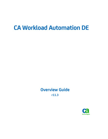
Industrial Automation Wiring and Grounding Guidelines3Route ConductorsTo guard against coupling noise from one conductor to another,follow these general guidelines (Table B) when routing wires andcables (both inside and outside of an enclosure). Use the spacinggiven in these general guidelines with the following exceptions: where connection points (for conductors of different categories)on a device are closer together than the specified spacing application-specific configurations for which the spacing isdescribed in a publication for that specific applicationThese guidelines are for noise immunity only. Follow all localcodes for safety requirements.Table BFollow these Guidelines for Routing Cables to GuardAgainst NoiseRoute this categoryof conductor cables:According to these guidelines:Category 1These conductors can be routed in the same cable tray or raceway with machine power conductors of up to 600V ac(feeding up to 100 hp devices).Category 2 If it must cross power feed lines, it should do so at right angles. Route at least 5 ft from high-voltage enclosures, or sources of rf/microwave radiation. If the conductor is in a metal wireway or conduit, each segment of that wireway or conduit must be bonded to eachadjacent segment so that it has electrical continuity along its entire length, and must be bonded to the enclosure at theentry point. Properly shield (where applicable) and route in a raceway separate from category-1 conductors. If in a contiguous metallic wireway or conduit, route at least 0.08m (3 in) from category-1 conductors of less than20A; 0.15m (6 in) from ac power lines of 20A or more, but only up to 100 kVA; 0.3m (1 ft) from ac power lines of greaterthan 100 kVA. If not in a contiguous metallic wireway or conduit, route at least 0.15m (6 in) from category-1 conductors of lessthan 20A; 0.3m (1 ft) from ac power lines of 20A or more, but only up to 100 kVA; 0.6m (2 ft) from ac power lines ofgreater than 100 kVA.Category 3Route conductors external to all raceways in the enclosure or in a raceway separate from any category-1 conductors withthe same spacing listed for category-2 conductors, where possible.Important: These guidelines assume that you follow thesurge-suppression guidelines (page 15). While these guidelinesapply to the majority of installations, certain electrically harshenvironments may require additional precautions.The use of the guidelines in Table B are illustrated in Figure 1.Publication 1770-4.1 – February 1998
4Industrial Automation Wiring and Grounding GuidelinesFigure 1Mounting Assembly DetailsCategory-2ConductorsCategory-1Conductors(ac Power Lines)ConduitTighter spacingallowedwith conduitConduitEnclosure WallUse greaterspacing withoutconduitTransformerTighter spacing allowedwhere forced by spacingof connection pointsCategory-2ConductorsI/O Block1771 I/O ChassisPlace modules tocomply with spacingguidelines if possibleMounting, Bonding, andGroundingPublication 1770-4.1 – February 199812618-IAfter establishing all layouts, you can begin mounting, bonding, andgrounding each chassis. Bonding is the connecting together of metalparts of chassis, assemblies, frames, shields, and enclosures toreduce the effects of emi and ground noise. Grounding is theconnection to the grounding-electrode system to place equipment atearth ground potential.
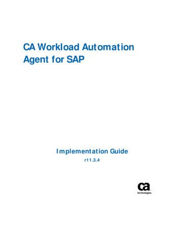
Industrial Automation Wiring and Grounding Guidelines5Mounting and Bonding the ChassisYou can mount the chassis with either bolts or welded studs.Figure 2 shows details for: stud-mounting a ground bus or chassis to the back panel of theenclosure stud-mounting a back panel to the enclosure bolt-mounting a ground bus or chassis to the back panel of theenclosureIf the mounting brackets of a chassis do not lay flat before the nutsare tightened, use additional washers as shims so that the chassisdoes not bend when you tighten the nuts.Important: Do not bend the chassis. Bending the chassis mightdamage the backplane and result in poor connections.Figure 2Mounting Assembly DetailsBack Wall ofEnclosureBack PanelMounting Bracketor Ground BusWelded StudFlatWasherScrape paintNutBack PanelWeldedStudNutFlatWasherStarWasherIf the mounting bracket is coatedwith a non-conductive material(anodized, painted, etc.), scrapethe material around the mountinghole.Stud mounting of a ground bus or chassis to the back panelUse a wire brush to removepaint from threads to allow aground connection.Scrape paint on panel anduse a star washer.Stud mounting of the back panel to the enclosure back wall17666Back PanelTappedHoleGround Bus orMounting Bracket17664Back PanelBoltMounting BracketTapped HoleFlatWasherNutStarWasherFlatWasherScrape paint on paneland use star washers.NutScrape paintFlatWasherFlatWasherIf the mounting bracket is coatedwith a non-conductive material(anodized, painted, etc.), scrapethe material around themounting hole.Bolt mounting of a ground bus or chassis to the back panelStarWasher17665BoltIf the mounting bracket is coated witha non-conductive material (anodized,painted, etc.), scrape the materialaround the mounting hole.Alternative bolt mounting of chassis to the back panel12342-IPublication 1770-4.1 – February 1998
6Industrial Automation Wiring and Grounding GuidelinesMake good electrical connection between each chassis, back-panel,and enclosure through each mounting bolt or stud. Wherever contactis made, remove paint or other non-conductive finish from aroundstuds or tapped holes.Bonding and Grounding the ChassisWith solid-state controls, proper bonding and grounding helpsreduce the effects of emi and ground noise. Also, since bonding andgrounding are important for safety in electrical installations, localcodes and ordinances dictate which bonding and grounding methodsare permissible.For example, for U.S. installations, the National Electrical Code(NEC) gives you the requirements for safe bonding and grounding,such as information about the size and types of conductors andmethods of safely grounding electrical components.Equipment-Grounding Conductor — In addition to making goodconnections through each bolt or stud, use either 1-inch copper braidor 8 AWG minimum stranded copper wire to connect each chassis,enclosure and central ground bus mounted on the back-panel. Figure3 shows ground-bus connection details.Figure 3Ground Bus Connection DetailsGround BusMountingGround BusEquipmentgroundingConductorsGroundLugTapped HoleStarWasherBoltGrounding-electrode conductorto grounding-electrode system.13271Figure 4 shows enclosure-wall ground connection details. Use asteel enclosure to guard against emi. If the enclosure door has aviewing window, it should be a laminated screen or a conductiveoptical substrate to block emi. Do not rely on the hinge for electricalcontact between the door and the enclosure; install a bonding wire.Publication 1770-4.1 – February 1998
Industrial Automation Wiring and Grounding Guidelines7Figure 4Details of Ground Connection at Enclosure WallEnclosureWallScrapePaintBoltGroundLugScrape paint on enclosure walland use a star washer.NutStarEquipmentWasher GroundingConductor10020Connect an equipment grounding conductor directly from eachchassis to an individual bolt on the ground bus. For a chassis withno ground stud, use a mounting bolt (Figure 5). For those chassiswith a ground stud, use the ground stud for this connection(Figure 6).Figure 5Details of Ground Connection at Mounting Bracket ofChassis with No Ground StudBack PanelMounting BracketWelded StudScrape paintGroundLugFlatWasherNutFlatWasherStarWasherIf the mounting bracket is coated with anon-conductive material (anodized,painted, etc.), scrape the materialaround the mounting hole.17666For a power supply without a groundable power supply chassis (suchas a power-supply module or mini-processor with an integral powersupply), or a power supply (such as the 1771–P7 or 1771–PS7) witha chassis that is not internally connected to its GND terminal, use a14 AWG copper wire to connect its GND terminal to the ground studor mounting bolt connected to the ground bus. This will ensure anadequate ground for noise immunity.Publication 1770-4.1 – February 1998
8Industrial Automation Wiring and Grounding GuidelinesFigure 6Typical Grounding ConfigurationEnclosure WallSee Figure 3See Figure 4GroundBusGroundingelectrodeConductorTo GroundingelectrodeSystem1756 Chassiswith 1756-PA72Power SupplyEquipment-groundingConductors 8AWGEquipment-groundingConductors 14AWGFLEX I/O ModulesDIN Rail1771-P7Power Supply1771 Chassiswith 1771-P7Power SupplyI/O Chassis Wall14 AWGMini-processor withbuilt-in power 1 Chassiswith 2 PowerSuppliesGround LugStarWasher14 AWGGroundBus15317Do not lay one ground lug directly on top of the other. This type ofconnection can become loose due to compression of the metal lugs.Sandwich the first lug between a star washer and a nut with a captivestar washer. After tightening the nut, sandwich the second lugbetween the first nut and a second nut with a captive star washer.Publication 1770-4.1 – February 1998
Industrial Automation Wiring and Grounding Guidelines9Some products have no visible groundable chassis and no ground lugor ground terminal, but mount on a DIN rail. The FLEX I/Oproducts are in this category. The chassis of these products aregrounded only thru the DIN rail. For these products, connect anequipment-grounding conductor directly from the mounting bolt onthe DIN rail to an individual bolt on the ground bus.Grounding-Electrode Conductor — Connect the ground bus tothe grounding-electrode system through a grounding-electrodeconductor. The grounding-electrode system is at earth-groundpotential and is the central ground for all electrical equipment and acpower within any facility. Use 8 AWG copper wire minimum for thegrounding-electrode conductor to help guard against emi. TheNational Electrical Code specifies safety requirements for thegrounding-electrode conductor.Shielded Cables — Certain I/O connections require shieldedcables to help reduce the effects of electrical noise coupling. Groundeach shield at one end only. A shield grounded at both ends forms aground loop which can cause a processor to fault.Ground each shield at the end specified in the appropriatepublication for the product. Never connect a shield to the commonside of a logic circuit (this would introduce noise into the logiccircuit). Connect each shield directly to a chassis ground.For some communication network cables, the shield connections areunique to the particular cabling system. In some such cases, a dcshort to ground is not needed because a low-impedance ac path toground and a high-impedance dc path to ground are providedinternally at each node. Follow the specific instructions in thepublication provided for the specific communication networkcabling system.Avoid breaking shields at junction boxes. Many types of connectorsfor shielded conductors are available from various manufacturers. Ifyou do break a shield at a junction box, do the following: Connect only category-2 conductors in the junction box. Do not strip the shield back any further than necessary to makea connection. Connect the shields of the two cable segments to ensurecontinuity along the entire length of the cable.Publication 1770-4.1 – February 1998
10Industrial Automation Wiring and Grounding GuidelinesYou can connect the power supply directly to the secondary of atransformer (Figures 7 and 8). The transformer provides dc isolationfrom other equipment not connected to that transformer secondary.Connect the transformer primary to the ac source; connect the highside of the transformer secondary to the L1 terminal of the powersupply; connect the low side of the transformer secondary to theneutral (common) terminal of the power supply.Power DistributionFigure 7Grounded ac Power-Distribution System with mingL2acL23FUL3To nd BusStep-down 2TransformerGrounded ConductorFUSEMultiple E-stop switchesGrounding-electrodeConductor oundingConductorsSuppressor1CRML1The I/O circuits form a netinductive load switched by theCRM contacts. Therefore, asuppressor is neededacross the line at the load sideof the CRM contacts.ControllerPower SupplyGNDConnect whenapplicableN or L2User sorOuputActuatorOutput ModuleWiring ArmCRM -To dc I/Oactuators/sensorsNotes:1 To minimize emi generation, connect a suppressor across an inductive load. For suppressors to use, refer to 11 andC or the Electrocube catalog.2 In many applications, a second transformer provides power to the input circuits and power supplies for isolationfrom the output circuits.3 Connect a suppressor here to minimize emi generation from the net inductive load switched by the CRM contacts. Insome installations, a 1mf 220W suppressor (Allen-Bradley 700-N5) or 2mf 100W suppressor (Electrocube PNRG1676-7) has been effective. For suppressors to use, refer to Figure 11 and Table C or the Electrocube catalog.Publication 1770-4.1 – February 199819241
Industrial Automation Wiring and Grounding Guidelines11Connect one input directly to the L1 side of the line, on the load sideof the CRM contacts, to detect whether the CRM contacts areclosed. In the ladder logic, use this input to hold off all outputsanytime the CRM contacts are open. (Refer to your programmingmanual.) If you fail to do this, closing the CRM contacts couldgenerate transient emi because outputs are already turned on. Tohave outputs turned on when CRM contacts are closing would beanalogous to squeezing the trigger on a hand tool as you’re pluggingit in.Figure 8Ungrounded ac Power-Distribution System withMaster-Control To n 2TransformerBack-panelGround BusFUSEX21LT2LTGrounding-electrodeConductor ctorsMultiple E-stop switchesStartCRMConnect whenapplicableSuppressor1CRMThe I/O circuits form a netinductive load switched by theCRM contacts. Therefore, asuppressor is neededacross the line at the load sideof the CRM contacts.L1ControllerPower SupplyGNDN or L2CRMUser sorOutputActuatorOutput ModuleWiring ArmCRM -To dc I/Oactuators/sensorsNotes:1 To minimize emi generation, connect a suppressor across an inductive load. For suppressors to use, refer to 11 and Cor the Electrocube catalog.2 In many applications, a second transformer provides power to the input circuits and power supplies for isolationfrom the output circuits.3 Connect a suppressor here to minimize emi generation from the net inductive load switched by the CRM contacts. Insome installations, a 1mf 220W suppressor (Allen-Bradley 700-N5) or 2mf 100W suppressor (Electrocube PNRG1676-7) has been effective. For suppressors to use, refer to Figure 11 and Table C or the Electrocube catalog.19240Publication 1770-4.1 – February 1998
12Industrial Automation Wiring and Grounding GuidelinesCommon Power Source for I/OUnless each I/O of a module or block is individually isolated,multiple I/O within the block or module share a common terminalfor one side of the power source. All I/O sharing a commonterminal must share a common power source (i.e., from the samepole of a disconnect or from the same transformer tap).If a module or block has multiple commons, each common and itsI/O may be isolated from the other commons. In that case, eachcommon and its I/O can have a separate power source. If each I/O isindividually isolated, each I/O can have a separate power source. Ifa module or block has individually isolated I/O or multiple isolatedcommons and multiple power sources are used, be certain that thedifference in potential between any two power sources does notexceed the specified maximum continuous voltage that can beapplied between the channels.Under-Voltage ShutdownEach power supply with under-voltage shut-down protectiongenerates a shut-down signal on the backplane when the ac linevoltage drops below its lower voltage limit. The power supplyremoves the shut-down signal when the line voltage comes backabove the lower voltage limit. This shut-down is to guard againstinvalid data being stored in memory.Because a capacitive-input power supply converting ac to dc drawspower only from the peak of the ac voltage wave-form, the externaltransformer load (in VA) of each power supply is 2.5 times its realpower dissipation (in Watts). If the transformer is too small, thepeaks of the sine wave are clipped. Even if the voltage is still abovethe lower voltage limit, the power supply senses the clipped wave aslow voltage and sends the shut-down signal.Sizing the TransformerTo determine the required rating of the transformer add theexternal-transformer load of the power supply and all other powerrequirements (input circuits, output circuits). The powerrequirements must take into consideration the surge currents ofdevices controlled by the processor. Choose a transformer with theclosest standard transformer rating above the calculatedrequirements.Publication 1770-4.1 – February 1998
Industrial Automation Wiring and Grounding Guidelines13For example, the external-transformer load of a 1771-P4Spower-supply module at maximum backplane load current is 140VA(2.5 x 56W 140). A 140VA transformer could be used if a1771-P4S power-supply module were the only load. A 500VAtransformer should be used if there were 360VA of load in additionto that of the 1771-P4S power-supply module.Second TransformerAllen-Bradley power supplies have circuits that suppresselectromagnetic interference from other equipment. However,isolate output circuits from power supplies and input circuits to helpprevent output transients from being induced into inputs and powersupplies. In many applications, power is provided to the inputcircuits and power supplies through a second transformer (Figure 9).Figure 9Power Supplies and Input Circuits Receiving Power througha Separate 23FUL3L3H4H1H3X1H1To on/Constant-VoltageTransformerX1X2To power suppliesand input circuitsTo output circuitsNotes:1 To minimize transient emi generation when power is interrupted by the interrupt switch,connect a suppressor across the primary of the transformer. Refer to Figure 11 andTable C for suppressors to use.Publication 1770-4.1 – February 199819242
14Industrial Automation Wiring and Grounding GuidelinesIsolation Transformer — For applications near excessiveelectrical noise generators, an isolation transformer (for the secondtransformer) provides further suppression of electromagneticinterference from other equipment. The output actuators beingcontrolled should draw power from the same ac source as theisolation transformer, but not from the secondary of the isolationtransformer (Figure 9).Constant-Voltage Transformer — In applications where the acpower source is especially “soft” and subject to unusual variations, aconstant-voltage transformer can stabilize the ac power source to theprocessor and minimize shutdowns. The constant-voltagetransformer must be of the harmonic neutralizing type.If the power supply receives its ac power through a constant-voltagetransformer, the input sensors connected to the I/O chassis shouldalso receive their ac power from the same constant-voltagetransformer. If the inputs receive their ac power through anothertransformer, the ac source voltage could go low enough thaterroneous input data enters memory while the constant-voltagetransformer prevents the power supply from shutting down theprocessor. The output actuators being controlled should draw powerform the same ac sources as the constant-voltage transformer, but notfrom the secondary of the constant-voltage transformer (9).Ground ConnectionWhen ac power is supplied as a separately derived system throughan isolation/step-down transformer, you can connect it as a groundedac system or an ungrounded ac system. For a grounded ac system,connect one side of the transformer secondary to the ground bus asin Figure 7. For an ungrounded ac system, connect one side of eachtest switch for the ground-fault-detector lights to the ground bus asin Figure 8. We do not recommend an ungrounded system. Followlocal codes in determining whether to use a grounded system.When bringing ac power into the enclosure, do not ground itsraceway to the ground bus on the back-panel. Connecting theraceway to the ground bus may cause the processor to fault byintroducing emi into the grounding circuit. Local codes may providean exception for permitting isolation from the raceway. Forexample, article 250-75 of the National Electrical Code has anexception that explains the conditions under which this isolationfrom the raceway is permitted.Publication 1770-4.1 – February 1998
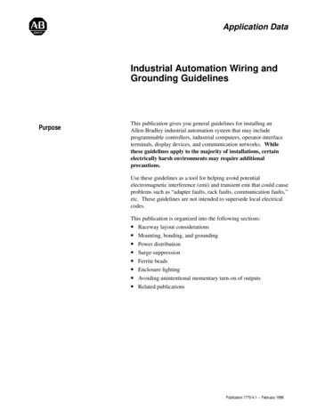
Industrial Automation Wiring and Grounding GuidelinesSurge-Suppression15Transient emi can be generated whenever inductive loads such asrelays, solenoids, motor starters, or motors are operated by “hardcontacts” such as pushbutton or selector switches. The wiringguidelines are based on the assumption that you guard your systemagainst the effects of transient emi by using surge-suppressors tosuppress transient emi at its source. Inductive loads switched bysolid-state output devices alone do not require surge-suppression.However, inductive loads of ac output modules that are in series orparallel with hard contacts require surge-suppression to protect themodule output circuits as well as to suppress transient emi.Figure 10 shows 3 examples of where to use suppressors. Inexample 1, although the motor-starter coil is an inductive load, itdoes not need a suppressor because it is switched by a solid-statedevice alone. In example 2, the relay coil needs a suppressorbecause a hard-contact switch is in series with the solid-state switch.However, in both examples 1 and 2, we show a suppressor on themotor and solenoid because it is an inductive load switched by thehard contacts of the motor starter or relay. Even if they have nointeraction with the control system, regularly cycled loads of thistype need suppression if conductors connecting to these loadsare: 1) connected to the same separately derived system as thatof the control system; 2) or routed in proximity with conductorsof the control system as per the routing guidelines.In example 3, the pilot light has a built-in step-down transformerthat needs a suppressor because it is an inductive load beingswitched by the hard contacts of a contact output module; withoutsuppression, the transient emi would be generated inside the I/Ochassis. Lights with built-in step-down transformers that areswitched by hard contacts external to any I/O chassis may not needto be suppressed because the noise spike they can generate may beonly approximately one tenth that of a relay or motor starter.In all cases, the ac power coming into the I/O modules must beswitched by the CRM contacts. Therefore, a suppressor is neededacross the line at the load side of the CRM contacts as shown inFigures 7 and 8. The application (voltage, net load of I/O circuits)dictates the specific suppressor needed across the line at the loadside of the CRM contacts.Publication 1770-4.1 – February 1998
16Industrial Automation Wiring and Grounding GuidelinesFigure 10Examples of where to use ough the motor starter is aninductive load, it does not need asuppressor because it is switchedby a solid-state device.ac output moduleL1L21MsuppressorThe motor needs supressorsbecause it is an inductive loadswitched by hard contacts.L1L21S1CR1CRsuppressorpilot light with built-instep-down transformersuppressorExample 2:An ac output modulecontrols an interposingrelay, but the circuit can beopened by hard contacts.The relay contacts controla solenoid.suppressorThe solenoid needs a supressorbecause it is an inductive loadswitched by hard contacts.The interposing relay needs asupressor because it is an inductiveload switched by hard contacts.L1Example 1:An ac output modulecontrols a motor starterwhose contacts control themotor.L1solid-stateswitchcontact output modulesuppressorsuppressorac output moduleL1Example 3:A contact output modulecontrols an inductive load.L2The pilot light needs a supressorbecause it is an inductive loadswitched by hard contacts.12597-IFigure 11 shows typical suppression circuitry for different types ofloads. Allen-Bradley bulletin 700 relays and bulletin 509 andbulletin 709 motor starters have surge-suppressors for their coilsavailable as an option. Table C lists some Allen-Bradley productsand their suppressors. See the Allen-Bradley Industrial ControlCatalog for more information on suppressors including Bulletin1492 surge-suppressor terminal blocks.Publication 1770-4.1 – February 1998
Industrial Automation Wiring and Grounding Guidelines17Figure 11Typical Suppression Applications230/460V acElectrocube 1676-13120V ac3-PhaseMotorCat. No. 700-N24For small apparatus (relays, solenoids, and motorstarters up to size 1)For 3-phase apparatus, a suppressor is needed across each phase 120/240V ac–V dcCat. No. 599-K04 or 599-KA04or ITW Paktron 104M06QC100700-NxFor large apparatus (con
painted, etc.), scrape the material around the mounting hole. Alternative bolt mounting of chassis to the back panel Mounting Bracket Star Washer Flat Washer Scrape paint 12342-I Bolt Tapped Hole Use a wire brush to remove paint from threads to allow a ground connection. Scrape paint on panel and use a star washer. Scrape paint on panel