Transcription
Test Procedures ManualBy Bob Allison, WB1GCM, ARRL Test EngineerMichael Tracy, KC1SX, ARRL Technical AdvisorMike Gruber, W1MG, ARRL EMC/RFI EngineerRevision history:Initial document: September 1990Revision A, October 1992, updates and correctionsRevision B, January 1996, major revision, additional tests addedRevision C, April 1997, updates and correctionsRevision D, November 1997, new graphics, updates and correctionsRevision E, August 1998, expanded test information addedRevision F, June 2000, BER test box changes addedRevision G, January 2002, new schematics added to Appendix ARevision H, June 2004, updates for new test equipment addedRevision I, January 2009, major revision, additional tests addedRevision J, June 2009, updates and correctionsRevision K, January 2010 updates and correctionsAmerican Radio Relay League, Inc., 1990-20101
TABLE OF CONTENTSI. PURPOSE AND SCOPEII. LIST OF FIGURESIII. LIST OF REQUIRED TEST INSTRUMENTSIV. TRANSMITTER TESTS4.1 OUTPUT POWER TEST4.2 TRANSMIT FREQUENCY RANGE TEST4.3 CW TRANSMIT-FREQUENCY ACCURACY TEST4.4 SPECTRAL PURITY TEST4.5 TWO-TONE TRANSMIT IMD TEST4.6 SSB CARRIER AND UNWANTED SIDEBAND SUPPRESSION AT 14.250 MHz4.7 CW KEYING WAVEFORM TEST4.8 PTT TO SSB/FM RF OUTPUT TEST4.9 TRANSMIT/RECEIVE TURN-AROUND TEST4.10 KEYER SPEED AND SIDETONE FREQUENCY TEST4.11 COMPOSITE NOISE TESTV. RECEIVER TESTS5.1 NOISE FLOOR TEST5.2 AM RECEIVE SENSITIVITY TEST5.3 FM SINAD AND QUIETING TEST5.4 RECEIVE FREQUENCY RANGE TEST5.5 FIRST IF AND IMAGE REJECTION TEST5.6 ANTENNA PORT ISOLATION TEST5.7 BLOCKING GAIN COMPRESSION5.7A RECIPROCAL MIXING5.8 TWO-TONE 2ND AND 3RD ORDER DYNAMIC RANGE TEST5.9 FM ADJACENT-CHANNEL SELECTIVITY TEST5.10 FM TWO-TONE 3RD ORDER DYNAMIC RANGE TEST5.11 AUDIO POWER OUTPUT TEST5.12 AUDIO AND IF FREQUENCY RESPONSE TEST5.13 SQUELCH SENSITIVITY TEST5.14 S METER TEST5.15 IN BAND IMD TEST5.16 NOTCH FILTER TEST5.17 DSP NOISE REDUCTION TEST5.18 EQUIVALENT RECTANGULAR BANDWIDTH TEST5.19 NOISE FIGURE CALCULATIONVI. NON-STANDARD AND SPECIAL PURPOSE TESTS6.1 LOW VOLTAGE AND TEMPERATURE CHAMBER TEST6.3 RECEIVER BIT-ERROR RATE TEST6.4 TRANSMITTER BIT-ERROR RATE TEST6.6 POWER METER TESTDATA SHEETS6.7 HF LINEAR AMPLIFIER TEST6.7B LINEAR AMPLIFIER IMD TESTLINEAR AMPLIFIER DATA SHEETABOUT THE LINEAR AMPLIFIER IMD TEST FIXTUREVII. APPENDIX A: ARRL CUSTOM TEST CIRCUITSVIII. APPENDIX B: FORMULAS FOR QST PRODUCT REVIEW 5136137163
PURPOSE AND SCOPE1.1 PURPOSEThe purpose of this manual is to ensure that all ARRL testing of HF transceivers, transmitters, and receivers will be conducted in aconsistent and well-defined manner. The procedures used for this testing have been broken down into clear, step-by-stepinstructions. All testing should be "done by the book" in order to guarantee that all equipment is evaluated to the same standards.This manual contains three major sections: Transmitter tests (Chapter 4), Receiver tests (Chapter 5) and Data Sheets (Chapter 6).The data sheets are arranged to allow test results to be recorded in the same order that measurements are taken.1.2 SCOPEThis manual is designed to cover a wide range of amateur HF equipment. It is not intended to replace common sense or theexpertise of an experienced test engineer. It is important, therefore, for the test engineer to be familiar with the Lab test equipmentand the Device Under Test (DUT). The manufacturer's manual for the DUT should be completely read and understood before anytesting is performed. At no time should any equipment be operated in a manner that is inconsistent with the manufacturer'srecommended procedures or published limits. Failure to understand the unit under test could result in test error or, even worse,damage to the equipment, or worst of all, damage to the test engineer.3
II. LIST OF FIGURESFigureDescription4-1Power Output Test Hook-Up4-2Transmit Frequency Range Test Hook-Up (no changes from 4-1)4-3CW Transmit Accuracy Test Hook-Up4-4Spectral Purity Test Hook-Up4-4AExample Spectral Purity Plot4-5Two-Tone Transmit IMD Test Hook-Up4-6SSB Carrier and Unwanted Sideband Suppression Test Hook-Up (no changes from 4-5)4-7CW Keying Waveform Test Hook-Up4-7AExample Scope Trace of RF Output CW Keying Waveform4-8PTT SSB/FM RF Output Test Hook-Up4-9Transmit/Receive Turn-Around Time Test Hook-Up4-10Keyer Speed and Side-tone Frequency Test Hook-Up4-11Composite Noise Test Hook-Up5-1CW Minimum Discernible Signal (MDS) Test Hook-Up5-2AM Receive Sensitivity Test Hook-Up5-3FM SINAD and Quieting Test Hook-Up5-4Receive Frequency Range Test Hook-Up5-5First IF and Image Rejection Test Hook-Up5-6Antenna Port Isolation Test Hook-Up5-7Blocking Gain Compression Test Hook-Up5-7AReciprocal Mixing Test Hook-Up5-8Two-Tone, 3rd Order Dynamic Range Test Hook-Up5-9FM Adjacent Channel Selectivity Test Hook-Up5-10FM Two-Tone, 3rd Order Dynamic Range Test Hook-Up5-11Audio Power Output Test Hook-Up5-12Audio and IF Frequency Response Test Hook-Up5-13Squelch Sensitivity Test Hook-Up5-14S-Meter Test Hook-Up5-15In-Band IMD Test Hook-Up5-16Notch Filter Test Hook-Up5-17Equivalent Rectangular Bandwidth Test Hook-Up6-1Low Voltage and Temperature Chamber Test Hook-Up6-2DSP Noise Reduction Test Hook-Up6-3Receiver Bit-Error-Rate (BER) Test Hook-Up6-4Transmitter Bit-Error-Rate (BER) Test Hook-Up6-5Receiver Phase-Noise Test Hook-Up4
II. LIST OF REQUIRED TEST INSTRUMENTSInstrument (or equivalent)Spectrum AnalyzerDistortion/Audio MeterRF Signal GeneratorRF Signal GeneratorIn-line RF WattmeterRF Signal GeneratorDigital Phosphor OscilloscopeTwo-Tone Audio GeneratorPower AttenuatorKeying-Test GeneratorAdjustable RF AttenuatorsHybrid CombinerVoltmeterAmmeterPhase-Noise Mixer14.025 MHz Low-Noise Osc.Power SupplyTelegraph KeyAttenuatorsHI-Z Audio Monitor AmpWideband Noise MT 543052BN/A8329N/A355C/D651 (2-60 MHz)N/AN/AN/AN/A6268BN/A8340-100 or similarN/AN-genQty.111111111111111111As R'qd115
IV. TRANSMITTER TESTS4.0.1 As shown in the Table of Contents, there are 11 transmitter tests outlined in this chapter. They have beenarranged to minimize the required number of hook-up changes and modifications. However, each hook-up is showncomplete, with all changes from the previous test clearly indicated. A block diagram accompanies each hook-up andany changes from the previous test are shown within a dotted rectangle. This affords the flexibility to easily startanywhere within the test plan and to perform these tests in any desired order.4.0.2 Before any transmitter testing is performed, it is essential for the test engineer to be completely familiar with theDevice Under Test (DUT) and the test equipment that will be used. The transmitter output power must not exceed thelimitations of any test equipment used or the manufacturer's specifications for the DUT – including duty cycle or time.The transmitter must be operated in a manner exactly as specified and be properly tuned. Any test in this manual thatwould cause a piece of equipment to be operated in a manner inconsistent with its manual must be accordinglymodified as required by the test engineer.4.0.2.1 Other considerations are as follows:Spectrum Analyzer/Frequency CounterThe input to the spectrum analyzer or frequency counter should not exceed the range of –5 dBm to 0 dBm.Therefore, it is necessary to attenuate the output of transmitters or amplifiers down to this level. For example,if a particular transmitter is rated at 100 watts output, it will be necessary to use 50 dB of attenuation to obtaina level of 0 dBm.RF Power MeterThe necessary element for the inline RF-power meter must be selected for the expected power and frequency.There are also multiplier switches on the wattmeter. Select the combination of switches that equals the powerrating of the element.RF Power and Step AttenuatorsRF power attenuators have an INPUT and an OUTPUT. Make sure that the RF source is connected to theINPUT of the power attenuator. Connecting RF power to the OUTPUT of the attenuator will result in damageto the attenuator or to the transceiver. The attenuators have a power rating, which must be observed. It isalways best to be conservative.6
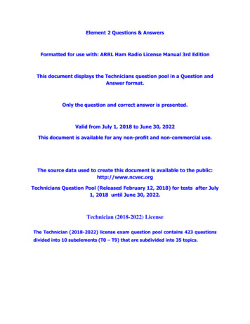
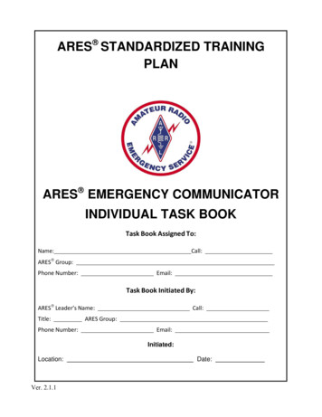
4.1 OUTPUT POWER TEST4.1.1 The purpose of the Transmitter Output Power Test is to measure the RF output power of the DUT across eachband in each of its available modes. A two-tone audio input, at a level within the manufacturer's microphone-inputspecifications, will be used for the SSB mode. No modulation will be used in the AM and FM modes. DC currentconsumption at the manufacturer's specified supply voltage is also measured, if applicable.4.1.2 Test hook-up (See Fig. 4-1)4.1.2.1 With all test equipment and DUT power switches in the OFF position and the transceiver in the receive mode,connect the following:ConnectionDUT RF OUTPUT to Wattmeter INPUTConnectorsAs Required to Type NCable Type50-Ohm CoaxWattmeter OUTPUT to RF Power AttenuatorType N to Type N50-Ohm CoaxTwo-Tone Audio Generator toDUT Microphone INPUTBanana or BNCto As RequiredCoaxTelegraph Key to DUT KEY INPUTAs RequiredAs RequiredAC power Only/AC Source toDUT Power InputAs Supplied with DUTAs Supplied with DUTDC Power OnlyAs Required1) Power supply to AC source.2) Power supply OUT to voltmeter and ammeter.3) Set power supply to specified voltage and connect to DUT.CAUTION!: Power must only be applied to theattenuator input! Do not reverse input and outputterminals of the Bird 8329.AC ONLYTWO-TONEAUDIOGENERATORAs RequiredDUTRF WATTMETERBIRD 4381TRANSMITTER100 WATTSTYPICAL100 WATTSTYPICALRF PowerAttenuator &Dummy LoadBird 8329PTT SWITCHTELEGRAPH KEYPOWERSUPPLYDC ONLYFig. 4-1 Power Output Test Hook-Up7
4.1.3 Test Procedure4.1.3.1 Turn the DUT and RF wattmeter power switches to ON and set the following controls:InstrumentTwo-Tone Audio GeneratorControlTONE ATONE BHI-Z/LO-ZBALANCELEVELAttenuatorPositionOFFOFFAs RequiredCenterFull CCW–30 dBRF WattmeterMode Select ButtonElementForward Element RangeFWD PEPAs RequiredAs RequiredDUTModeBAND SelectorXMIT/RCVDRIVE or RF LEVELCWLowest AvailableReceiveMinimum4.1.3.2 Allow all equipment at least 10 minutes warm-up time before proceeding to step 4.1.3.34.1.3.3 Tune the DUT per the operator’s manual. Put the DUT in the CW transmit mode at minimum DRIVE/RFLEVEL.NOTE: The following three paragraphs, 4.1.3.4 , 4.1.3.5 and 4.1.3.6 apply only to transceivers with a DCpower supply. Skip these paragraphs if testing an ac-powered DUT and make a note of the power type onData Sheet.4.1.3.4 Depress telegraph key. Observe that some minimum level of RF power is shown by the DUT Power OutputMeter and Bird Wattmeter. Increase the RF DRIVE/LEVEL control if necessary. Record the power-supply ammeterand voltmeter values in 4.1.3.4 of the data sheet.4.1.3.5 Increase RF DRIVE/LEVEL control to the maximum allowed by the manufacturer. Again, depress thetelegraph key and record the power-supply meter readings in 4.1.3.5 of the data sheet. Decrease the RF DRIVEcontrol to minimum. Release the telegraph key.4.1.3.6 Increase the DUT AF gain control to maximum. (There should be no input signal.) Any light or displayillumination should be in the default position. Measure and record the power supply readings as in the previous step.4.1.3.7 Depress the key and observe the DUT power output meter and wattmeter indications. Slowly tune the DUT tothe upper band edge while observing these meters. Release the key and record the maximum value observed on thewattmeter in 4.1.3.7 of the data sheet.4.1.3.8 Increase the DRIVE/RF LEVEL control to the maximum allowed. Depress the telegraph key. Slowly tunethe DUT down to the lower band edge while observing both the DUT power output meter and wattmeter as in theprevious step. Release the telegraph key and record the minimum wattmeter values observed in 4.1.3.8 of the datasheet. Return the DRIVE/RF LEVEL control to minimum.4.1.3.9 Set the DUT for the lower edge of the 80-meter band and retune as necessary. Repeat steps 4.1.3.7 and4.1.3.8. Record all values in 4.1.3.9 of the data sheet. Repeat this procedure for all the remaining bands. Record boththe DUT power output meter and wattmeter indications for the 20-meter band. Note any significant deviations in theDUT meter indication observed between bands.8
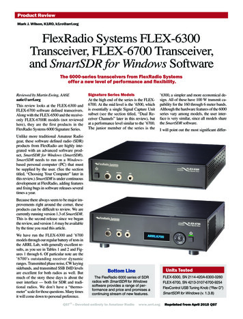
4.1.3.10 Return the transmitter to the lower edge of the 20-meter band and retune as necessary. Set the two-tone audiogenerator power switch to ON. Adjust for proper balance between both tones by setting the BALANCE control to theposition so indicated. Adjust the generator LEVEL control for maximum specified ALC. Set the RF wattmeter toFWD PEP. Place the DUT in the USB mode and tune as required with the DUT mic gain control set about half-way.Adjust the audio generator for maximum audio as specified by the manufacturer's manual with the DUT mic gaincontrol set about half-way.4.1.3.11 Repeat steps 4.1.3.7 and 4.1.3.8 and using the PTT switch to key the transmitter. Verify similar poweroutput performance with the DUT in the LSB mode. Note any significant deviation from the USB mode. RecordDUT power output meter and wattmeter indications in 4.1.3.11 of the Data Sheets.4.1.3.12 Set the RF Wattmeter to FWD CW and the two-tone generator power switch to OFF. Return the transmitterto the lower edge of the 80-meter band. Place the DUT in the AM mode. Repeat steps 4.1.3.7 and 4.1.3.8 using thePTT switch to key the transmitter. Be sure not to exceed the maximum power output specified by the manufacturer forthis mode. Record DUT power output meter and wattmeter indications in 4.1.3.12 of the Data Sheets.4.1.3.13 Return the transmitter to the lower edge of the 10-meter band. Place the DUT in the FM mode. Repeat steps4.1.3.7 and 4.1.3.8 for this mode. Be sure not to exceed the maximum power output specified by the manufacturer forthis mode.NOTE: Proceed to the following step only if the DUT has a transverter output.4.1.3.14 Put the DUT into the CW mode and activate the transverter function. Set to the 15 meter band. Connect theHP-437 microwatt meter and any needed attenuation to the transverter output. (Input to the microwatt meter must notexceed 20 dBm.) Repeat steps 4.1.3.7 and 4.1.3.8. Record on Data Sheet. Also observe and record any RF outputthat may appear at the normal antenna output.4.2 TRANSMIT FREQUENCY RANGE TEST4.2.1 The purpose of the Transmit Frequency Range Test is to determine the range of frequencies, including thoseoutside amateur bands, for which the transmitter may be used.4.2.2 Test Hook-up (See Fig. 4-2)NOTE: No further hook-up changes are required if proceeding directly from the previous Power Output Test.This hook-up procedure, therefore, does not apply in this case and you may now proceed to step 4.2.3.1.4.2.2.1 Connect the following with all power switches in the OFF position and the transceiver in the receive mode:ConnectionDUT RF OUTPUT to Wattmeter INPUTConnectorsAs Required to Type NCable Type50-Ohm CoaxWattmeter OUTPUT to RF Power AttenuatorType N to Type N50-Ohm CoaxTelegraph Key to DUT KEY INPUTAs RequiredAs RequiredAC power Only/AC Source to DUT Power InputAs Supplied with DUTAs Supplied with DUTDC Power Only1) Power supply to AC source.2) Power supply OUT to voltmeter and ammeter.As RequiredAs Required9
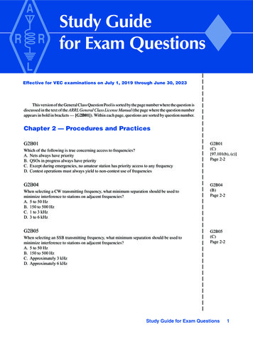
3) Set power supply to specified voltage and connect to DUT.CAUTION!: Power must only be applied tothe attenuator input! Do not reverse inputand output terminals of the Bird 8329.TWO-TONEAUDIOGENERATORDUTTRANSMITTERRF WATTMETERBIRD 4381100 WATTSTYPICAL100 WATTSTYPICALRF PowerAttenuator &Dummy LoadBird 8329TELEGRAPH KEYPOWER SOURCEFig. 4-2 Transmit Frequency Range Test Hook-up4.2.3 Test Procedure4.2.3.1 Turn the DUT and RF wattmeter power switches to ON and set the following controls:InstrumentRF WattmeterControlMode select buttonElementPower RangePositionFWD CWAs RequiredAs RequiredDUTModeBand SelectorXMIT/RCVDRIVE/RF OUTCWLowest available bandRECEIVEMinimum4.2.3.2 Allow all equipment at least 10 minutes warm up time.4.2.3.3 Tune the DUT per the operator’s manual for the lowest available band. Return the DRIVE/RF OUTPUTcontrol to minimum. (The DUT should still be in the CW mode.)4.2.3.4 Tune down near the low end of the band. Depress the telegraph key. Observe some minimum RF indicationon the wattmeter. Slowly tune down until the RF drops out or the manufacturer's specified limit is achieved. Releasethe key and record this frequency, as indicated by the DUT display in 4.1.3.4 of the data sheet.4.2.3.5 Tune to the upper limit of the band. Again, depress the telegraph key and slowly tune up until the RF dropsout. Release the key and record this frequency in 4.1.3.5 of the data sheet.4.2.3.6 Repeat steps 4.1.3.3 to 4.1.3.5 for all remaining available bands on the DUT.10
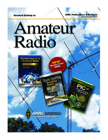
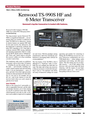
4.3 CW TRANSMIT-FREQUENCY ACCURACY TEST4.3.1 The purpose of the CW Transmit-Frequency Accuracy Test is to measure and compare the actual outputfrequency of the DUT with its display adjusted for 14.000 MHz down to the least significant available digit.4.3.2 TEST HOOK-UP (See Fig. 4-3)NOTE: If proceeding directly from the previous Transmit Frequency Range Test, you need only modify theexisting hook-up. Proceed to the steps indicated with a dotted line.4.3.2.1 With all power switches in the OFF position and the transceiver in the receive mode, connect the following:ConnectionDUT RF OUTPUT to wattmeter INPUTConnectorsAs Required to type NCable Type50-Ohm coaxWattmeter OUTPUT to Power Attn INPUTType N to type N50-Ohm ---------------------Pwr Attn OUT to 10-dB step INPUTType N to BNC50-Ohm coax10-dB step Attn OUT to 1-dB step INBNC to BNC50-Ohm coax1-dB step ATTN OUT to Freq Counter INBNC to BNC50-Ohm ---------------------Telegraph key to DUT KEY INPUTAs RequiredAs RequiredAC or DC power to DUTAs RequiredAs RequiredCAUTION!: Power must only be appliedto the attenuator input! Do not reverseinput and output terminals of the Bird8329.TWO-TONEAUDIOGENERATORDUTRF WATTMETERBIRD 4381TRANSMITTER100 WATTSTYPICAL100 WATTSTYPICALRF PowerAttenuator &Dummy LoadBird 8329TELEGRAPH KEYPOWER SOURCE10 dB STEPATTENUATOR1 dB STEPATTENUATORHP 355DHP 355CDO NOTEXCEED0 dBm!FREQUENCYCOUNTERHP-5351BFig. 4-3 CW Transmit Accuracy Test Hook-up11
4.3.3 Test Procedure4.3.3.1 Turn the DUT, RF wattmeter and frequency counter power switches to ON. Set the following controls:InstrumentDUTControlModeBand SelectorFrequencyXMIT/RCVDRIVE/RF OUTPositionCW20 Meters14.000 00 MHzRECEIVEMinimumRF WattmeterMode Select ButtonElementPower RangeFWD CWAs RequiredAs Required10-dB Step Attn1-dB Step AttnAttenuatorAttenuator40 dBAnyFrequency Counter50 Ohm50 Ohm (Depress)4.3.3.2 Key the transmitter. Observe the minimum output power on the RF wattmeter and unkey the transmitter. Setthe step attenuators to provide –5 to 0 dBm input to the frequency counter.Do not exceed the maximum input limitation to the Frequency Counter.4.3.3.3 Check and readjust, if necessary, the DUT for 14.000 00 MHz as indicated by its display. Record this value ifthe DUT has a digital type display, or, as best as possible with an analog display.4.3.3.4 Key the transmitter and note the frequency as indicated by both the DUT and the frequency counter. Place acheck mark in 4.3.3.4 of the data sheet if there is any significant deviation from 14.000 00 MHz4.3.3.5 Increase the step attenuators to 40 dB. Set the transmitter power to the maximum allowed. Key the transmitterand observe the RF output power as shown by the wattmeter. Set the attenuators to provide –5 to 0 dBm input to thecounter.4.3.3.6 Key the transmitter. Record the DUT and Frequency Counter indications in 4.3.3.6 of the Data Sheet. Unkeythe transmitter.4.3.3.7 Reduce the voltage to 12 V dc (if using a DC supply). Again key the transmitter and note the frequencydisplayed on the DUT and frequency counter. Place a check mark in 4.3.3.7 of the data sheet if there is any significantdeviation from initial data.12
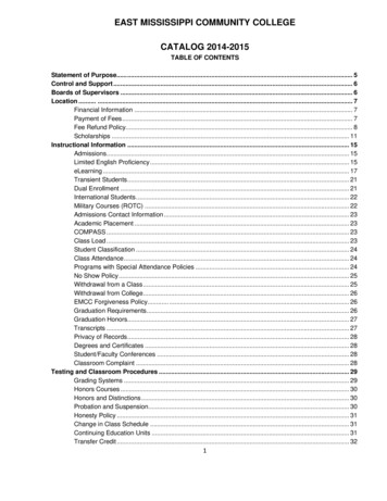
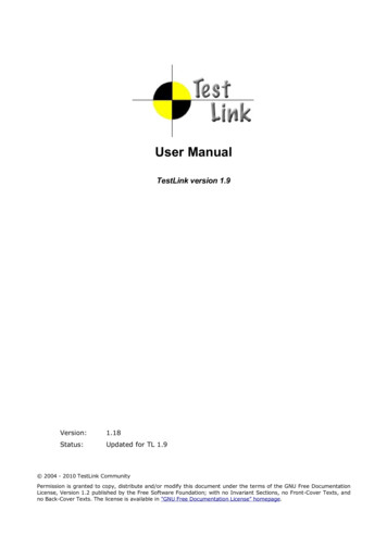
4.4 SPECTRAL PURITY TEST4.4.1 The purpose of the Spectral Purity Test is to determine and measure the content of any spurious emissions in theoutput of the transmitter. Full-power carriers will be examined and minimum power checked on all available bands.4.4.2 Test hook-up (See Fig. 4-4)NOTE: If proceeding from the previous Transmit Frequency Accuracy Test, skip to the steps indicated with adotted line.4.4.2.1 With all power switches in the OFF position and the transceiver in the receive mode, connect the following:ConnectionDUT RF OUTPUT to wattmeter INPUTConnectorsAs Required to type NCable Type50-Ohm coaxWattmeter OUTPUT to Power Attn INPUTType N to type N50-Ohm coaxPower Attn OUT to 10-dB step INPUTType N to BNC50-Ohm coax10-dB step Attn OUT to 1-dB step INBNC to BNC50-Ohm -------------------------1-dB step Attn OUT to Spec Analyzer INBNC to BNC50-Ohm -------------------------Telegraph key to DUT KEY INPUTAs RequiredAs RequiredAC or DC power to DUTAs RequiredAs RequiredCAUTION!: Power must only be applied tothe attenuator input! Do not reverse inputand output terminals of the Bird 8329.TWO-TONEAUDIOGENERATORDUTRF WATTMETERBIRD 4381TRANSMITTER100 WATTSTYPICAL100 WATTSTYPICALRF PowerAttenuator &Dummy LoadBird 8329TELEGRAPH KEYPOWER SOURCE10 dB STEPATTENUATORHP 355D1 dB STEPATTENUATORHP 3555CDO NOTEXCEED0 dBmSPECTRUMANALYZERHP 8563EFig. 4-4 Spectral Purity Test Hook-up13
Fig. 4-4A Example Spectral Purity Plot4.4.3 Test Procedure4.4.3.1 Turn the DUT, RF wattmeter and spectrum analyzer power switches to ON and set the following controls:InstrumentDUTControlModeBand SelectorXMIT/RCVDRIVE/RF LEVELPositionCWLowest availableReceiveMinimumRF WattmeterPush Button Mode SelectElementForward Element RangeFWD CWAs RequiredAs Required10-dB Step Attn1-dB Step AttnAttenuatorAttenuator40 dBAnySpectrum AnalyzerSTART FREQ - STOP FREQREF LEV (AMPLITUDE)ATTEN (AMPLITUDE)RES BW (BW)VIDEO BW (BW)THRESHOLD (DISPLAY)SWP TIME (SWEEP)0 – 50 MHz–10 dBm20 dB10 kHz30 kHz–80 dBmAUTO4.4.3.2 NOTE: If proceeding directly from the previous CW Transmit Frequency Accuracy Test, skip this paragraph.Receiver hiss should be heard; adjust volume to desired level. Allow all equipment at least 10 minutes warm-up timebefore proceeding to step 4.4.3.3.4.4.3.3 Tune the DUT per the operator's manual at the low end of the band. Put the DUT in the CW transmit mode atmaximum DRIVE/RF LEVEL.14
4.4.3.4 Depress the telegraph key and observe the power output shown by the Bird wattmeter. Release the key and setthe step attenuators for –10 dBm input to the spectrum analyzer. CAUTION: The input to the spectrum analyzer at notime should exceed 10 dBm. Damage to this instrument will occur at an input level of 30 dBm or greater.14.4.3.5 Key the transmitter. The largest pip to the right of 0 MHz should be the fundamental. (This may be verifiedby use of the PEAK SEARCH button. With the marker to be at the top of the pip, the indicated marker frequencyshould be very close to the transmitted frequency.)4.4.3.6 Adjust the REF LEV control on the spectrum analyzer so that the peak of the fundamental pip is at the LogRef (0 dB) line on top of the display graticule. (To optimize the display, the FREQ START-FREQ STOP may be setfor 0-10 MHz and the RES BW may be set for 30 kHz on the 160-meter band.)4.4.3.7 The spectrum analyzer is now calibrated. The smaller pips are harmonics or spurs. The level of each spur, indB below the fundamental, can be read directly from the display graticule. Each horizontal division represents 5 MHzeach in the case of a 0-50 MHz frequency range. The frequency range may be adjusted for the specific display beingconsidered, or as deemed appropriate by the test engineer. Each vertical division represents 10 dB.4.4.3.8 Turn on the crystal calibrator, if the DUT has one, and observe any spurious emissions created by thecalibrator. Record in notes section of data sheet and turn off the calibrator.4.4.3.9 Slowly tune up the band while observing the analyzer display. Retune as necessary if the transmitter is not abroadband type. Note the worst case observed. Record on data sheet.4.4.3.10 Reduce the transmitter power output to minimum. Again, observe the analyzer display while tuning down tothe lower band edge. Note the worst case observed and record on data sheet.4.4.3.11 Repeat steps 4.4.3.9 and 4.4.3.11 for all remaining available bands on the DUT. The Frequency Rangesettings for each band are as follows:1.8 MHz14 MHz28 MHz50 MHz144 MHz222 MHz432 MHz:0-50 MHz0-100 MHz0-200 MHz0-500 MHz0-1000 MHz0-1000 MHz0-2000 MHz4.4.3.12 Return the transmitter to the worst case on the worst band. With the all significant spurs visible on thescreen, take a single sweep by depressing the SGL SWP button. (Typically, this will be the second or third harmonic,although it is possible for VHF parasitic to be present.) The START FREQ, STOP FREQ and RES BW may be variedas required. Record all information on data sheet and save the plot to an appropriately named file.1"Woe be unto he who breaks this thing." Edward F. Hare, W1RFI15
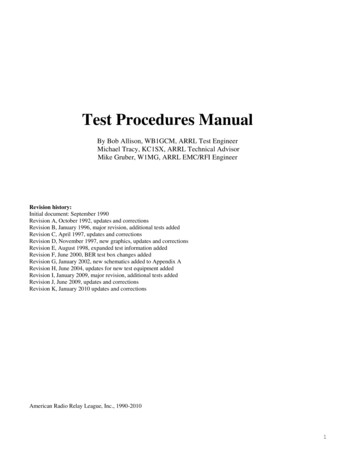
4.5 TWO-TONE TRANSMIT IMD TEST4.5.1 The purpose of the Two-Tone Transmit Test is to measure the intermodulation-distortion (IMD) productspresent in the RF output of the DUT transmitter. The transmitter will be operated in the SSB mode at 3.900 MHz and14.250 MHz initially and then on all other available bands subsequently. A two-tone audio input at frequencies of 700and 1900 Hz, within the manufacturer's amplitude specifications, will be used.4.5.2 Test hook-up (See Fig. 4-5)NOTE: If proceeding in the test series, only the two-tone generator, shown within the dotted line, must be addedto the previous Spectral Purity Test hook-up for the IMD Test.4.5.2.1 With all power switches in the OFF position and the transceiver in the receive mode, connect the following:ConnectionDUT RF OUT To Wattmeter INConnectorsAs Required To Type NCable Type50-Ohm CoaxWattmeter OUT To PWR Attn INType N To Type N50-Ohm CoaxPWR Attn OUT To 10-dB Step INType N To BNC50-Ohm Coax10-dB Step OUT To 1-dB Step INCoaxBNC To BNC50-OhmConnectionConnectorsCable Type1-dB Step OUT To Spectrum Analyzer INBNC To BNC50 Ohm -------------------------Two-Tone Generator OUT To DUT MIC IN BNC To As ---------------------------------Power to DUTAs RequiredAs RequiredCAUTION!: Power must only be applied tothe attenuator input! Do not reverse inputand output terminals of the Bird 8329.TWO-TONEAUDIOGENERATORDUTRF WATTMETERBIRD 4381TRANSMITTER100 WATTSTYPICAL100 WATTSTYPICALRF PowerAttenuator &Dummy LoadBird 8329TELEGRAPH KEYPOWER SOURCE10 dB STEPATTENUATORHP 355D1 dB STEPATTENUATORHP 3555CDO NOTEXCEED0 dBmSPECTRUMANALYZERHP 8563EFig. 4-5 Two-Tone Transmit IMD Test Hook-up4.5.3 Test Procedure4.5.3.1 Turn on the DUT, RF wattmeter and spectrum analyzer and set the following controls:InstrumentDUT16ControlModeBand SelectorPositionLSB80 Meters
FrequencyXMIT/RCVDRIVE or RF LEVELMicrophone3.900 00 MHzRECEIVEMinimumMinimumTwo-Tone GeneratorTONE A (700 Hz)TONE B (1900 Hz)HI-Z/LO-ZBALANCELEVELAttenuatorOFFOFFAs RequiredCenterFull CCW–30 dBRF WattmeterPush Button Mode SelectElementForward Element RangeFWD PEPAs RequiredAs Required10-dB Step Attn1-dB Step AttnAttenuatorAttenuator–40 dBAnySpectrum Analyzer(Menu in Parentheses)CENTER FREQ (FREQUENCY)SPAN (SPAN)REF LEV (AMPLITUDE)ATTEN (AMPLITUDE)RES BW (BW)VIDEO BW (BW)THRESHOLD (DISPLAY)SWP TIME (SWEEP)3.89870 MHz20 kHz–40 dBm20 dB100 Hz10 kHz–110 dBmAUTO4.5.3.2 NOTE: If proceeding from the previous tests, this paragraph may be skipped.Receiver hiss should be heard; adjust the volume to the desired level. Allow all equipment at least 10 minuteswarm-up time before proceeding to step 4.5.3.3.4.5.3.3 Tune the DUT per the operator's manual for the test frequency of 3.900 MHz. Turn on the two-tone generatorand set both tone switches to ON. With the DUT in the LSB mode, set the generator LEVEL and ATTENUATORcontrols for the maximum audio input as specified by the manufacturer. If the manufacturer does not list aspecification for this figure, adjust the 2-tone generator’s amplitude for maximum rated RF output of the transmitterwith the transmitter’s microphone gain near maximum. Observe the transmitter power as shown by the wattmeter.Ensure that the output power of the DUT is not greater than the manufacture's maximum power output rating. Unkeythe transmitter and set the step attenuators for approximately -46 dBm input to the spectrum analyzer.CAUTION: The input to the spectrum analyzer at no time should exceed 10 dBm.4.5.3.4 Place the DUT in the VOX mode and verify operation with the signal generator. Note on data sheet if VOXdoes not function correctly. Return the DUT to the PTT mode and key the transmitter. Set the BALANCE control onthe generator for equal tone amplitude as shown on the display. Adjust the CENTER FREQ, if necessary, so that thedisplay center is half-way between the two pips. The IMD-distortion products should now be visible.4.5.3.5 Adjust the REF LEVEL control (and step attenuators, if necessary) for the peak of the two pips to be at –6 dB.The spectrum analyzer is now calibrated. The amplitude of each IMD distortion product may now be read in dB PEP(dB below the peak envelope power) directly from the display.17
4.5.3.6 Manipulate, if necessary, t
Test Procedures Manual By Bob Allison, WB1GCM, ARRL Test Engineer . Dummy Load Bird 8329 100 WATTS TYPICAL 100 WATTS TYPICAL RF WATTMETER B . TELEGRAPH KEY DUT TRANSMITTER POWER SUPPLY Fig. 4-1 Power Output Test Hook-Up . 8 4.1.3 Test Procedure 4.1.3.1 Turn the DUT and RF wattmeter power switches to ON and set the following controls .