Transcription
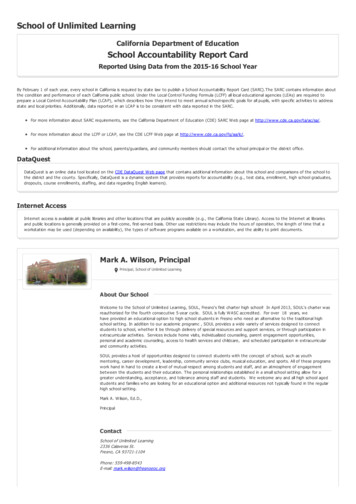
TechnicalReviewProductby MarkSpencer,WA8SMEMarkJ. Wilson,K1RO,k1ro@arrl.orgFlexRadio Systems FLEX-6300Transceiver, FLEX-6700 Transceiver,and SmartSDR for Windows SoftwareThe 6000-series transceivers from FlexRadio Systemsoffer a new level of performance and flexibility.Reviewed by Martin Ewing, AA6Eaa6e@arrl.orgThis review looks at the FLEX-6300 andFLEX-6700 software defined transceivers.Along with the FLEX-6500 and the receiveonly FLEX-6700R models (not reviewedhere), they are the first products in theFlexRadio Systems 6000 Signature Series.Signature Series ModelsAt the high end of the series is the FLEX6700. At the mid level is the ’6500, whichis essentially a single Signal Capture Unitsubset (see the section titled, “Dual Receiver Channels” later in this review), butat a performance level similar to the ’6700.The junior member of the series is the’6300, a simpler and more economical design. All of these have 100 W transmit capability for the 160 through 6 meter bands.Although the hardware features of the 6000series vary among models, the user interface is very similar, since all models sharethe SmartSDR software.I will point out the most significant differ-Unlike more traditional Amateur Radiogear, these software defined radio (SDR)products from FlexRadio are highly integrated with an advanced software product, SmartSDR for Windows (SmartSDR).SmartSDR needs to run on a Windowsbased personal computer (PC) that mustbe supplied by the user. (See the sectiontitled, “Choosing Your Computer” later inthis review.) SmartSDR is under continuousdevelopment at FlexRadio, adding featuresand fixing bugs in software releases severaltimes a year.Because there always seem to be major improvements right around the corner, theseproducts can be difficult to review. We arecurrently running version 1.3 of SmartSDR.This is the second release since we beganthe review, and version 1.4 may be availableby the time you read this article.We have run the FLEX-6300 and ’6700models through our regular battery of tests inthe ARRL Lab, with generally excellent results, as you see in Tables 1 and 2 and Figures 1 through 6. Of particular note are the’6700’s outstanding receiver dynamicranges. Transmitted phase noise, CW keyingsidebands, and transmitted SSB IMD levelsare excellent for both radios as well. Butmuch of the story these days is about theuser interface — both for SDR and traditional radios. We don’t have a “thermo meter” scale for those questions. Many timesit will come down to personal preference.Units TestedBottom LineThe FlexRadio 6000 series of SDRradios with SmartSDR for Windowssoftware provides a range of performance and price and promises acontinuing stream of new features.QST – Devoted entirely to Amateur Radiowww.arrl.orgFLEX-6300, SN 2114-420A-6300-0260FLEX-6700, SN 4213-3107-6700-9254FlexControl USB Tuning Knob (“Rev D”)SmartSDR for Windows (v. 1.3.8)Reprinted from April 2015 QST
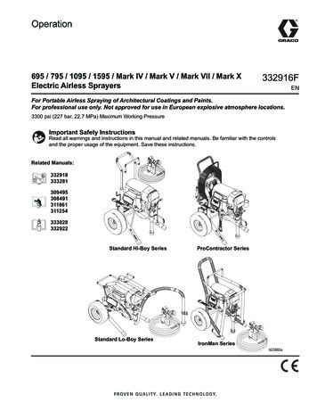
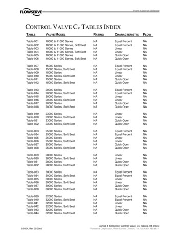
Key MeasurementsSummaryTable 1FlexRadio FLEX-6300, serial number 2114-420A-6300-0260RM12120 6014020 kHz Reciprocal Mixing Dynamic Range129BG127 14020 7020 kHz Blocking Gain Compression (dB)81I39220 5011020 kHz 3rd-Order Dynamic Range (dB)RM1166021402 kHz Reciprocal Mixing Dynamic Range128BG2126 140702 kHz Blocking Gain Compression (dB)I3292501102 kHz 3rd-Order Dynamic Range (dB)38»I343» 3520 -4020 kHz 3rd-Order Intercept (dBm)I3243»-40 302 kHz 3rd-Order Intercept (dBm)-32*I3TX -20-41**-35Transmit 3rd-Order IMD (dB)-52*I9TX -20-54**-70Transmit 9th-Order IMD (dB)PR093Key: » Off ScaleDynamic range and interceptvalues with preamp off.Intercept values were determinedusing –97 dBm reference80 M20 M* Worst case band, 160 meters** TypicalReprinted from April 2015 QSTManufacturer’s SpecificationsMeasured in the ARRL LabFrequency coverage: Receive, 0.03 – 54 MHz;transmit, 160, 80, 60, 40, 30, 20, 17, 15,12, 10, and 6 meter amateur bands.Power requirement: Receive, 1.7 A typical;transmit, 23 A maximum at 13.8 V dc 15%.Modes of operation: SSB, CW, AM,synchronous AM, RTTY, FM.*Receive, 0.100 – 54.1 MHz;transmit, as specified.ReceiverReceiver Dynamic TestingAt 13.8 V dc (typical): transmit, 16 A;receive, 1.6 A; off, 38 mA.As specified.Noise floor (MDS) in 500 Hz BW:Noise floor (MDS), 500 Hz bandwidth:–121/–125/–136 dBm (preamp off/Preamp off Preamp on10 dB, 20 dB).0.137 MHz–114 dBmN/A**0.475 MHz–119 dBmN/A**1.0 MHz–119 dBmN/A**3.5 MHz–119 dBmN/A**14 MHz–119 dBm–128 dBm29 MHz–118 dBm–136 dBm50 MHz–118 dBm–135 dBmNoise figure: Not specified.Preamp off/on: 14 MHz, 28/19 dB;50 MHz, 29/12 dB.Spectral sensitivity: Not specified.–138 dBm (100 kHz screen bandwidth);–146 dBm (5 kHz screen bandwidth,maximum averaging).AM sensitivity: Not specified.10 dB (S N)/N, 1-kHz, 30% modulation,6 kHz bandwidth:Preamp offPreamp on1.0 MHz8.41 µVN/A**3.8 MHz8.31 µVN/A**29 MHz9.88 µV1.08 µV50 MHz11.0 µV1.24 µVBlocking gain compression dynamic range:Blocking gain compression dynamic range,Not specified.500 Hz bandwidth:20 kHz offset5/2 kHz offsetPreamp off/on Preamp off3.5 MHz129 dB/**128/128 dB14 MHz127/127 dB127/126 dB50 MHz128/126 dB127/127 dBReciprocal mixing dynamic range: Not specified.14 MHz, 20/5/2 kHz offset: 121/117/116 dB.ARRL Lab Two-Tone IMD Testing (500 Hz ut LevelIMD LevelIMD DR3.5 MHz/Off20 kHz–38 dBm–119 dBm81 dB–7 dBm–97 dBmCalculatedIP3 3 dBm 38 dBm14 MHz/Off20 kHz–27 dBm–4 dBm0 dBm–119 dBm92 dB–97 dBm–83 dBm 19 dBm 43 dBm 42 dBm14 MHz/On20 kHz–39 dBm–28 dBm–128 dBm89 dB–97 dBm 6 dBm 7 dBm14 MHz/Off5 kHz–27 dBm–4 dBm0 dBm–119 dBm92 dB–97 dBm–84 dBm 19 dBm 43 dBm 42 dBm14 MHz/Off2 kHz–27 dBm–4 dBm0 dBm–119 dBm92 dB–97 dBm–84 dBm 19 dBm 43 dBm 42 dBm50 MHz/Off20 kHz–24 dBm–11 dBm–118 dBm94 dB–97 dBm 23 dBm 32 dBm50 MHz/On20 kHz–43 dBm–22 dBm–135 dBm93 dB–97 dBm 5 dBm 16 dBmARRL, the national association for Amateur Radio www.arrl.org
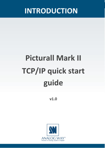
QS1504-ProdRev01Measured in the ARRL LabSecond-order intercept point: Not specified.Image rejection: 80 dB.Preamp off/on, 14 MHz, 63/ 57 dBm;21 MHz, 67/ 67 dBm;50 MHz, 65/ 57 dBm.Not tested. See text.22 dB (normal), 44 dB (deep),64 dB (very deep).S-9 signal, preamp off/on 14 MHz,60.9/55.5 µV; 50 MHz; 51.2/54.3 µV.Range at –6 dB points (bandwidth) ††CW (400 Hz): 399 – 800 Hz (401 Hz);Equivalent rectangular BW: 397 Hz;USB (2.4 kHz):94 – 2496 Hz (2402 Hz);LSB (2.4 kHz): 94 – 2496 Hz (2402 Hz).AM (6.0 kHz): 64 – 3009 Hz (5890 Hz).99 dB.TransmitterTransmitter Dynamic TestingPower output: CW/SSB/FSK/FM, 100 W;AM, 25 W.CW/SSB/FSK: HF, 1 W minimum, 84 –99 W maximum depending on band.50 MHz, 1 – 86 W. AM: HF typically0.2 – 28 W; 50 MHz, 0.15 – 20 W.FM: N/A.* Power output typically 5 Wlower at minimum operating voltage.HF, 60 dB worst case (1.8 MHz); 65 dB.typical. 50 MHz, 66 dB. Complies withFCC emission standards. 70 dB. 70 dB.100 W PEP, 3rd/5th/7th/9th order:–32/–51/–52/–52 dBc (worst case, 160 m);–41/–42/–48/–54 dBc (HF, typical);–50/–38/–51/ –60 dBc (50 MHz).4.9 to 104 WPM, iambic mode A and B.See Figures 1 and 2.S-9 signal, AGC fast, 184 ms.DSP noise reduction: Not specified.Notch filter depth: Not specified.S-meter sensitivity: Not specified.IF/audio response: Not specified.Spurious-signal and harmonic suppression:HF, 50 dB; 50 MHz, 70 dB.SSB carrier suppression: 80 dB.Undesired sideband suppression: 80 dB.Third-order intermodulation distortion (IMD):Not specified.CW keyer speed range: Not specified.CW keying characteristics: Not specified.Transmit-receive turn-around time (PTT releaseto 50% audio output): Not specified.Receive-transmit turn-around time (tx delay):SSB, 138 ms.Not specified.Composite transmitted noise: Not specified.See Figure 3.Size (height, width, depth): 3.9 12.8 12.6 inches including protrusions; weight, 10 lb.Price: FLEX-6300, 2499; 6300-ATU autotuner, 299; FlexControl, 99.95.00.01 0.02 0.03 0.04 0.05 0.06 0.07 0.08Time (s)Figure 1 — CW keying waveform for theFLEX-6300 showing the first two dits in fullbreak-in (QSK) mode using external keying.Equivalent keying speed is 60 WPM. The uppertrace is the actual key closure; the lower trace isthe RF envelope. (Note that the first key closurestarts at the left edge of the figure.) Horizontaldivisions are 10 ms. The transceiver was beingoperated at 94 W output on the 14 MHz –100fc-4fc 2fcFrequency in kHzfc-2fc 4Figure 2 — Spectral display of the FLEX-6300transmitter during keying sideband testing.Equivalent keying speed is 60 WPM usingexternal keying. Spectrum analyzer resolutionbandwidth is 10 Hz, and the sweep time is 30seconds. The transmitter was being operated at94 W PEP output on the 14 MHz band, and thisplot shows the transmitter output 5 kHz fromthe carrier. The reference level is 0 dBc, and thevertical scale is in dB.*FM operation was not available in the tested configuration but is scheduled for SmartSDR Version 1.4.**Although the specifications indicate two levels of preamplification (10 dB or 20 dB) the reviewtransceiver just offered Preamp Off or Preamp On. The preamp is not available for the 3.5 MHzband or lower frequencies to avoid interference from the AM Broadcast Band.†ARRL Product Review testing includes Two-Tone IMD results at several signal levels.Two-Tone, Third-Order Dynamic Range figures comparable to previous reviews are shownon the first line in each group. The “IP3” column is the calculated Third-Order Intercept Point.Second-order intercept points were determined using –97 dBm reference.††Default values; bandwidth is adjustable via DSP.www.arrl.orgQS1504-ProdRev030 20Phase Noise (dBc/Hz)Figure 3 — Spectral display of the FLEX-6300 transmitter outputduring phase noise testing. Power output is 94 W on the 14 MHzband (blue trace), and 86 W on the 50 MHz band (red trace). Thecarrier, off the left edge of the plot, is not shown. This plot showscomposite transmitted noise 100 Hz to 1 MHz from the carrier. Thereference level is 0 dBc, and the vertical scale is in dB.QST – Devoted entirely to Amateur RadioQS1504-ProdRev020Response (dB)Manufacturer’s Specifications 40 60 80 100 12050 MHz 140 160100 Hz14 MHz1 kHz 10 kHz 100 kHz 1 MHzFrequency OffsetReprinted from April 2015 QST
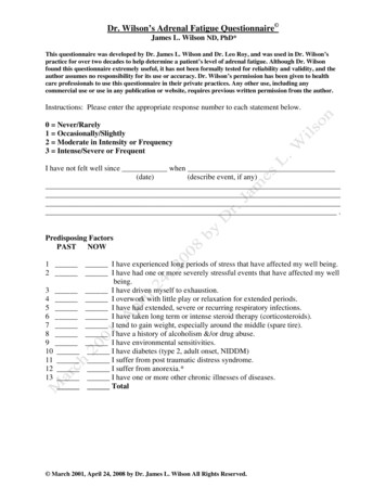
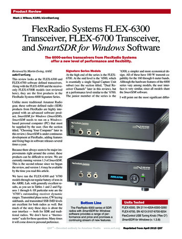
Key MeasurementsSummaryTable 2FlexRadio FLEX-6700, serial number 4213-3107-6700-9254RM124 14020 6020 kHz Reciprocal Mixing Dynamic Range126BG128 14020 7020 kHz Blocking Gain Compression (dB)103I3103 11020 5020 kHz 3rd-Order Dynamic Range (dB)RM1166021402 kHz Reciprocal Mixing Dynamic Range126BG2128 140702 kHz Blocking Gain Compression (dB)I32103 110502 kHz 3rd-Order Dynamic Range (dB)40»I346» 3520 -4020 kHz 3rd-Order Intercept (dBm)I3246» 30-402 kHz 3rd-Order Intercept (dBm)-32*I3TX -20-41**»Transmit 3rd-Order IMD (dB)-35-55*I9TX -20-55**-70Transmit 9th-Order IMD (dB)PR094Key: » Off ScaleDynamic range and interceptvalues with preamp off.Intercept values were determinedusing –97 dBm reference80 M20 M* Worst case band, 12 meters** TypicalReprinted from April 2015 QSTManufacturer’s SpecificationsMeasured in the ARRL LabFrequency coverage: Receive, 0.03 – 77,135 – 175 MHz; transmit, 160, 80, 60, 40, 30,20, 17, 15, 12, 10, and 6 meter amateur bands.Power requirement: Receive, 2 A typical;transmit, 23 A maximum at 13.8 V dc 15%.Modes of operation: SSB, CW, AM,synchronous AM, RTTY, FM.*Receive, 0.100 – 74, 136 – 165 MHz;transmit, as specified.ReceiverReceiver Dynamic TestingAt 13.8 V dc (typical): transmit, 16 A;receive, 1.75 A.As specified.Noise floor (MDS) in 500 Hz BW:Noise floor (MDS), 500 Hz bandwidth:–121/–125/–136/–141 dBm (preamp off/Preamp Off/1/2/310 dB, 20 dB, 30).0.137 MHz–115 /–116 /–123 /–80 dBm0.475 MHz–119 /–123 /–132 /–116 dBm1.0 MHz–119 /–123 /–132 /–127 dBm3.5 MHz–119 /–125 /–135 /–140 dBm14 MHz–119 /–125 /–135 /–140 dBm50 MHz–118 /–124 /–135 /–140 dBm70 MHz–116 /–123 /–133 /–139 dBm144 MHz–116 /–123 /–133 /–138 dBmNoise figure: Not specified.Preamp off/1/2/3:14 MHz28/22/12/7 dB50 MHz29/23/12/7 dB70 MHz31/24/14/8 dB144 MHz32/24/14/9 dBSpectral sensitivity: Not specified.–144 dBm (100 kHz screen bandwidth);–157 dBm (1.2 kHz screen bandwidth,maximum averaging).AM sensitivity: Not specified.10 dB (S N)/N, 1-kHz, 30% modulation,6 kHz bandwidth:Preamp Off/1/2/31.0 MHz7.24/3.80/1.26/2.82 µV3.8 MHz8.12/3.23/1.15/0.80 µV29.0 MHz8.03/3.89/0.90/0.80 µV50.4 MHz9.65/5.01/1.26/0.81 µV70.4 MHz12.20/5.43/1.51/0.95 µV144.4 MHz17.20/6.68/1.97/1.13 µVBlocking gain compression dynamic range:Blocking gain compression dynamic range,Not specified.500 Hz bandwidth:20 kHz offset5/2 kHz offsetPreamp off/1/2/3Preamp off3.5 MHz 126/126/126/122 dB 126/126 dB14 MHz 128/129/130/125 dB 128/128 dB50 MHz 128/131/132/127 dB 128/ 128 dB70 MHz 126/129/130/126 dB 126/126 dB144 MHz 126/129/131/128 dB 126/126 dBReciprocal mixing dynamic range: Not specified.14 MHz, 20/5/2 kHz offset: 124/117/116 dB.ARRL Lab Two-Tone IMD Testing (500 Hz t LevelIMD LevelIMD DR†3.5 MHz/Off20 kHz–16 dBm–119 dBm103 dB–6 dBm–97 dBm14 MHz/Off20 kHz–16 dBm–119 dBm103 dB–2 dBm–97 dBm0 dBm–88 dBm14 MHz/120 kHz–25 dBm–125 dBm100 dB–11 dBm–97 dBm14 MHz/220 kHz–28 dBm–135 dBm107 dB–17 dBm–97 dBm14 MHz/320 kHz–42 dBm–140 dBm94 dB–28 dBm–97 dBm14 MHz/Off5 kHz–16 dBm–119 dBm103 dB–2 dBm–97 dBm0 dBm–90 dBm14 MHz/Off2 kHz–16 dBm–119 dBm103 dB–2 dBm–97 dBm0 dBm–90 dBmARRL, the national association for Amateur Radio CalculatedIP3 36 dBm 40 dBm 36 dBm 46 dBm 44 dBm 25 dBm 32 dBm 26 dBm 23 dBm 1 dBm 7 dBm 36 dBm 46 dBm 45 dBm 36 dBm 46 dBm 45 dBmwww.arrl.org
QS1504-ProdRev04Measured in the ARRL Lab50 MHz/Off20 kHz50 MHz/320 kHz70 MHz/Off20 kHz70 MHz/320 kHz144 MHz/Off20 kHz144 MHz/320 kHz–18 dBm–1 dBm–40 dBm–28 dBm–48 dBm–9 dBm–41 dBm–24 dBm–34 dBm–7 dBm–43 dBm–22 dBmSecond-order intercept point: Not specified.MeasuredIMD DR†–118 dBm100 dB–97 dBm–140 dBm100 dB–97 dBm–116 dBm68 dB–97 dBm–139 dBm98 dB–97 dBm–116 dBm82 dB–97 dBm–138 dBm95 dB–97 dBmCalculatedIP3 32 dBm 47 dBm 10 dBm 7 dBm–14 dBm 35 dBm 8 dBm 13 dBm 7 dBm 38 dBm 5 dBm 16 dBmImage rejection: 100 dB.Preamp off/1/2/3:14 MHz, 87/ 87/ 87/ 87 dBm;50 MHz, 85/ 85/ 85/ 85 dBm;70 MHz, 25/ 67/ 63/ 39 dBm;144 MHz, 89/ 87/ 87/ 79 dBm.Not tested. See text.19 dB (normal), 39 dB (deep), 70 dB (very deep).S-9 signal, 14 MHz, 50.1 µV;50 MHz, 46.7 µV; 144 MHz, 33.1 µV.Range at –6 dB points (bandwidth) ††CW (400 Hz): 399 – 800 Hz (401 Hz);Equivalent rectangular BW: 399 Hz;USB (2.4 kHz):98 – 2496 Hz (2402 Hz);LSB (2.4 kHz): 98 – 2502 Hz (2403 Hz).AM (6.0 kHz): 65 – 3008 Hz (5886 Hz).107 dB.TransmitterTransmitter Dynamic TestingPower output: CW/SSB/FSK/FM, 100 W;AM, 25 W.CW/SSB/FSK: HF, 1 W minimum, 87 –99 W maximum depending on band.50 MHz, 1 – 82 W. AM: HF typically0.2 – 27 W; 50 MHz, 0.3 – 19 W.FM: N/A.* Power output typically 5 Wlower at minimum operating voltage.HF, 59 dB worst case (24 MHz); 65 dB.typical. 50 MHz, 68 dB. Complies withFCC emission standards. 70 dB. 70 dB.100 W PEP, 3rd/5th/7th/9th order:–32/–40/–44/–55 dBc (worst case, 12 m);–41/–44/–48/–55 dBc (HF, typical);–41/–38/–50/ –60 dBc (50 MHz).5 to 50 WPM, iambic modes A and B.See Figures 4 and 5.S-9 signal, AGC fast, 198 ms.DSP noise reduction: Not specified.Notch filter depth: Not specified.S-meter sensitivity: Not specified.IF/audio response: Not specified.Spurious-signal and harmonic suppression:HF, 60 dB; 50 MHz, 70 dB.SSB carrier suppression: 80 dB.Undesired sideband suppression: 80 dB.Third-order intermodulation distortion (IMD):Not specified.0QST – Devoted entirely to Amateur 60–70–80–90–100fc-2fc 2fcFrequency in kHzfc-4fc 4Figure 5 — Spectral display of the FLEX-6700transmitter during keying sideband testing.Equivalent keying speed is 60 WPM usingexternal keying. Spectrum analyzer resolutionbandwidth is 10 Hz, and the sweep time is 30seconds. The transmitter was being operated at87 W PEP output on the 14 MHz band, and thisplot shows the transmitter output 5 kHz fromthe carrier. The reference level is 0 dBc, and thevertical scale is in dB.QS1504-ProdRev060 20CW keyer speed range: Not specified.CW keying characteristics: Not specified.Transmit-receive turn-around time (PTT releaseto 50% audio output): Not specified.Receive-transmit turn-around time (tx delay):SSB, 140 ms.Not specified.Composite transmitted noise: Not specified.See Figure 6.Size (height, width, depth): 4.0 13.0 12.6 inches including protrusions; weight, 13 lb.Price: FLEX-6700, 7499; GPSDO GPS disciplined oscillator, 699; FlexControl, 99.95.*FM operation was not available in the tested configuration but is scheduled for SmartSDR Version 1.4.**ARRL Product Review testing includes Two-Tone IMD results at several signal levels.Two-Tone, Third-Order Dynamic Range figures comparable to previous reviews are shownon the first line in each group. The “IP3” column is the calculated Third-Order Intercept Point.Second-order intercept points were determined using –97 dBm reference.†Two-Tone, Third-Order IMD dynamic range figures are “up to” the value indicated.See QST, Feb 2010, page 52. Note that the IMD DR increases with Preamp 2 on, which is theopposite of typical traditional superhet receivers. (Engaging Preamp 2 puts the sensitivity morein line with that of other radios.) An important characteristic of direct sampling radios is thatdynamic range increases with the signal strength of the interfering signals. IMD DR increaseswith Preamp 2 (20 dB gain) engaged because the noise floor goes down by 16 dB and the driveto the ADC goes up by 20 dB. The increased drive to the ADC improves IMD DR performance.††Default values; bandwidth is adjustable via DSP.0.01 0.02 0.03 0.04 0.05 0.06 0.07 0.08Time (s)Figure 4 — CW keying waveform for the FLEX6700 showing the first two dits in full-break-in(QSK) mode using external keying. Equivalentkeying speed is 60 WPM. The upper trace is theactual key closure; the lower trace is the RF envelope. (Note that the first key closure starts atthe left edge of the figure.) Horizontal divisionsare 10 ms. The transceiver was being operatedat 87 W output on the 14 MHz band.Response (dB)ARRL Lab Two-Tone IMD Testing (500 Hz bandwidth)** [continued]MeasuredBand/PreampSpacingInput LevelIMD LevelPhase Noise (dBc/Hz)Manufacturer’s Specifications 40 60 80 100 12050 MHz 140 14 MHz 160100 Hz1 kHz 10 kHz 100 kHz 1 MHzFrequency OffsetFigure 6 — Spectral display of the FLEX-6700transmitter output during phase noise testing.Power output is 87 W on the 14 MHz band (bluetrace), and 82 W on the 50 MHz band (red trace).The carrier, off the left edge of the plot, is notshown. This plot shows composite transmittednoise 100 Hz to 1 MHz from the carrier. The reference level is 0 dBc, and the vertical scale is in dB.www.arrl.orgReprinted from April 2015 QST
In the ’6500 and ’6700, the ADC runs at245 Msps.In this view of the FlexRadio SmartSDR software, a total of eight separate receivers areopen and running simultaneously.ences between the FLEX-6300, ’6500, and’6700 as we go. More information about thedifferences among the models is availablefrom the FlexRadio website.A Software Defined RadioFlexRadio Systems has pioneered softwaredefined radios (SDR) for the general Amateur Radio market. In earlier models, thesampling occurred at a low IF frequency,in the kilohertz range. This permitted sampling up to about 100 kHz at one time,which could be shown as an instantaneouspanadapter power spectrum and over timeas a waterfall plot. This is a key feature ofmost SDR radios, by the way, being able tovisualize a large swath of spectrum showing all the activity on an amateur band — oreven the entire HF spectrum — so you cansee where the action is at a glance. You canclick on a point on the display, and a smallslice of the spectrum will be demodulatedas an SSB, CW, AM, or FM signal.The “ideal” SDR is one where the conversion from analog to digital occurs as early— as close to the antenna — as possible.This will eliminate most of the “messy”(drifting, noisy, expensive) analog components in favor of digital processing.FlexRadio has taken on that challenge andproduced the FLEX-6300 that samples theRF spectrum up to 54 MHz. The ’6500samples up to 77 MHz. The ’6700 alsosamples to 77 MHz, but adds another 30MHz segment, 135 – 165 MHz. Analogcircuitry rejects out-of-band signals andprovides switching and preamplificationbefore analog-to-digital conversion. Theoverall scheme is shown in Figure 7.The switching, filtering, and preamplification are traditional, but after that we’re inSDR territory. The FLEX-6300 analogto-digital converter (ADC) produces 122million 16-bit samples per second (Msps).FPGAFilterADCAnt. 2Antenna SwitchAnt. 1FilterATUADCThe block labeled “DaVinci Processor”refers to an embedded ARM Cortex-A8chip from Texas Instruments supportingthe Linux operating system.2 It does nothave a direct user interface. The DaVinciprocessor accepts data from the FPGAand provides further filtering and signaldemodulation. Audio inputs and outputsare provided directly on the Flex box orremotely through your PC and LAN (localarea network). Remote LAN operation willrequire SmartSDR Version 1.4 or later.One of the most important elements of anyof the 6000 series radios is “customer supplied equipment,” namely your Windowspersonal computer. (There is no nativesupport for Macintosh or Linux computers at this time.) The FlexRadio hardwarecommunicates with your PC through anEthernet connection (at least 100 Mb/s).Two-way digital audio transmissions areprovided through custom DAX drivers installed in Windows.DaVinci ProcessorUser PCPanadapterFFTPanadapter ProcessingSmartSDR for Windows,digimodes, logging, etc.Tune & DecimationFilter & DemodulationUp to 8 InstancesFilterIn terms of computing power, the majorblock in Figure 7 is the field programmablegate array (FPGA), a Xilinx Virtex-6 chip.1This is a specialized computing engine wellsuited for DSP operations, such as the fastFourier transform (FFT). Up to eight parallel programs in the FLEX-6700 (four in the’6500 or two in the ’6300) run in the FPGA,each one computing the data necessary fora single panadapter/waterfall display. TheFPGA reduces the torrent of input data bya large factor so that further processing canbe done in general purpose computing environments.DAXUp to 8 InstancesPanadapterFFTPanadapter ProcessingTune & DecimationFilter & DemodulationUP SamplerModulation &Power ControlDACEthernetMouseKeyboardMonitors(dual ?)Audio: Mic, Speaker, PhonesLocalMic, Speaker,Phones,KeyQS1504-ProdRev07Figure 7 — FLEX-6000 signal flow diagram (adapted from FlexRadio Systems)Reprinted from April 2015 QSTARRL, the national association for Amateur Radio www.arrl.org
The block diagram also indicates the transmitter signal flow, which is more-or-lesslike the receiver’s, but in reverse. Morefiltering, power amplification, and an automatic antenna tuner complete the transceiver. (For the FLEX-6300, the antennatuner is an optional extra.)Dual Receiver ChannelsThe FLEX-6700 has two identical majorreceiver channels called Signal CaptureUnits — SCUs . (The ’6500 and ’6300have only one SCU.) Why would youwant two SCUs when each one can takein the entire HF spectrum? It is true thatwith a single SCU, you can create up toeight panadapters in the ’6700 (four in the’6500, and two in the ’6300), and you candemodulate up to eight signals (using SliceReceivers — in FlexRadio lingo) anywherein the panadapter bands. (Up to four SliceReceivers are allowed in the ’6500 and twoin the ’6300.) There is no problem whenoperating “split” in a single band, or monitoring phone and CW subbands at the sametime. But if you use a single SCU acrossmultiple bands, you can’t use the ham bandpreselector filters. You will be switched into“wide” mode, where the receiver is wideopen across the spectrum and potentiallymore susceptible to out-of-band interference. (The ’6300 has no preselectors, so itis always in wide mode.)With two independent SCU samplers andswitchable preselectors, the FLEX-6700is super versatile. You can have optimumreception on two different bands with separate antennas, or you can have one receiveron HF and the other on VHF with a transverter. You can set up diversity reception,fast QSK, and probably other creative configurations.QS1504-Prodrev08Frequency Offset (Hz)0.6 0.04 ppm0.40.20.0-0.2-0.4-0.6050001000015000Time (sec)20000Figure 8 — Apparent frequency of WWV,showing FLEX-6700 stability.FlexControl USB Tuning KnobMany users will say that a “real radio” needs a tuning knob, that tuning by mousepointing and clicking is not the whole story. The FlexRadio Systems FlexControl USBTuning Knob is an optional addition to a 6000-series SDR radio that takes care ofthat little issue.Installation of the FlexControl should have been a snap, but it was not. A number ofreboots and software settings were required to get SmartSDR talking to the FlexControl. The problem apparently was that the FlexControl was initially installed on a COMport that interfered with SmartCAT’s assignments. Once I reset the FlexControl’sCOM port to 4 before assigning SmartCAT ports, everything began working reliably.The big rotary knob has a great feel, and it spins nicely. Don’t spin too fast though,because SmartSDR’s internal retuning rate is limited. There are three additionalbuttons, which can be programmed to set the knob’s current action: controlling aslice receiver tuning, RIT, audio volume, and so on. An LED indicator tells you whichbutton is active. Unfortunately, the FlexControl’s physical labeling has no relationshipto any SmartSDR function!I did some work that allows the FlexControl to be used with Linux software projects.See tml.Frequency ReferencesI am one of those who worry about the accuracy and stability of a transceiver’s frequency reference. If the dial indicates “Hz,”the frequency accuracy should be better than1 Hz! Modern radios typically offer stabilityin the 1 part per million (ppm) range. Often,the reference oscillator is a temperaturecompensated crystal oscillator (TCXO). TheFLEX-6500 and ’6300 use a TCXO quoting0.5 ppm stability. This is adequate for mostamateur operation, but it could be a problemfor critical HF and VHF work. (A 1 ppmoffset is 50 Hz on 6 meters!) The ’6700 provides much better performance with anoven-controlled crystal oscillator (OCXO)and quoted stability of 0.02 ppm.radio will be an excellent, albeit expensive,tool to ace the ARRL Frequency Measurement Tests!Stability is mostly about frequency changesover a period of minutes or hours. It doesnot guarantee accuracy. An oscillator is accurate if it operates very close to its ratedfrequency. Out of the box, at about 70 Fambient temperature and without correction, I found our FLEX-6700 reference wasabout 0.08 ppm high, while our ’6300 wasabout 0.5 ppm low. (The exact numberswill vary among production radios.) Theseerrors are not serious, because you cancorrect for them by entering a frequencyoffset in SmartSDR. Under steady ambientconditions, I found that both radios werequite stable over a period of hours at the 0.04 ppm level or better. Looking at thisin more detail, I recorded WWV’s apparentfrequency at 10 MHz using the ’6700 andFldigi software for frequency measurementas shown in Figure 8.3 Most of the fluctuations are probably propagation effects. ThisThe GPSDO does not support GPS timekeeping, but adding a network time serverfunction to SmartSDR seems feasible. Thiswould give your station precise time synchronization independent of the Internet —useful for portable or emergency situations.Flex can add that to their to-do list!QST – Devoted entirely to Amateur RadioIf you are seeking ultimate frequencycontrol, both the FLEX-6700 and ’6500provide for an optional GPS DisciplinedOscillator (GPSDO), which locks yourradio to the atomic frequency standardsbehind the Global Positioning Satellitesystem. FlexRadio quotes stability of 5 10-12 over 24 hours for this 699 option.While this is far beyond normal amateurrequirements, it will appeal to the TimeNuts crowd.4 If you sync all your oscillatorsto the 10 MHz GPS stabilized output, youmight have fun operating JT65 at 100 GHz!Transverter OperationThe FLEX-6700 should be popular amongVHF folks who need a high-quality basesystem to operate with transverters for thehigher bands. The ’6700 and ’6500 offera lot of flexibility for this application, supporting transverters with split IF connections or common IF (send and receive on asingle cable). (The ’6300 requires the common IF setup.) Figures 9 and 10 show therear panels of both transceivers.I connected my Elecraft XV144 transverterwith a split 28 MHz IF setup to the FLEX-www.arrl.orgReprinted from April 2015 QST
6700. It went on the air with no specialproblems. SmartSDR helpfully allows youto enter the frequency conversion scheme,along with any local oscillator (LO) offset,so that SmartSDR displays the correct RFfrequency scale. Up to 17 different transverter schemes are allowed, which shouldsatisfy most of us!Two MetersThe FLEX-6700 will support the 2 meterband directly, with 8 dBm output powerat the transverter jack. This capability canbe used to work with a higher frequencytransverter that may require an IF in the 135– 165 MHz range. While you can operatedirectly on 2 meters, most amateurs wouldwant to use external transmit and receiveamplification. At least one 2 meter linearamp and receive preamp is being marketedspecifically for the ’6700.5You might prefer to use the FLEX-6700’s2 meter capability rather than a transverterbecause you get a simpler hook-up and fullcoverage of the band, which is not availablewith many transverters. You also get the benefit of the ’6700’s precise frequency control.Choosing Your ComputerSmooth operation of the Flex 6000 radiosdepends on your Windows PC, which mustbe powerful enough to support computation, communications, and display of largeamounts of data. You don’t want to skimpon the PC, but how much is enough?It is hard to define a minimum requiredsystem, because computer performance hasso many dimensions: CPU speed,
and SmartSDR for Windows Software The 6000-series transceivers from FlexRadio Systems offer a new level of performance and flexibility. Product Review Mark J. Wilson, K1RO, k1ro@arrl.org Bottom Line The FlexRadio 6000 series of SDR radios with SmartSDR for Windows software provides a range of per-formance and price and promises a