Transcription
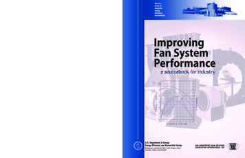
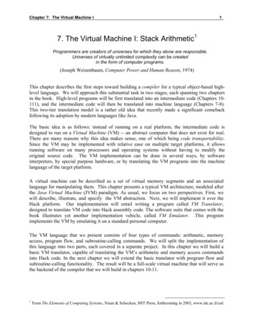
VERTICAL HI-RISE/STACK FAN COIL UNITSModel Series 39VH & 39LFeatures and BenefitsAVERTICAL HI-RISE/STACK FAN COIL UNITSA2Engineered Comfort fan coil units arethe only true commercial quality fancoil units available today. They arealso the most versatile units on themarket, because Engineered Comfortoffers the largest list of options andfeatures. Variable Air Volume Cooling andHeating with ECM / EPIC FanTechnology eliminatesnoisy3-speed fans and provides superiorroom comfort (optional). ECM Motor will save 67% of theenergy at typical set points (moreat others), which gives the owner amajor reduction in electrical usage(optional). Motor/blower combinations aremounted on special 16 ga. (1.61)angles and isolated from casing withrubber insulators. The units are designed for easyinstallation and, with modularconstruction, easy repair. Units are available with chilled / hotwater coils and electric heat. All units are certified by AHRI andlisted by ETL and display the AHRIand ETL symbols. Coil options allow for 3 to 5 rowchilled water and 1 or 2 row hotwater. 5 rows total in combination. The units are shipped completelyassembled to reduce field labor cost. All units are fully inspected and runtested at the factory to eliminatepotential problems at start up. Available with stand-alone electroniccontrols, Digital controls (BacNetcompliant) or with factory mountedDigital controls supplied by others. Factory supplied controls are testedand calibrated at the factory. Custom needs that are job specificcan be incorporated into the units Ultra-violet light option helpskeep the coil clean and reducesre-circulation of microbes whichreduces: Allergy Asthma, Upperrespiratory ailments, Headaches,Sinus congestion and even Coldsand Flu. Most models can be configured in astand alone, master/slave or pairedarrangement. Risers (2 and 4 pipeconfigurations) can be located onthe back, left or right side of unit Commercial Grade Supply Grille(s)are available on the front, left orright side of unit Quarter turn latches for easy,quick panel removal and access Removable controls enclosure Powder coat painted finish resistsscuffing and scratching Slide out blower for easymaintenance Nailor ECM/EPIC Fan Technology ,ECM Motor with variable airvolume (optional) Stainless steel flex hoses withfull port ball valves UV Light w/safety switch (optional) Factory mounted control valvesand piping packages Filter rack Coils are AHRI 410 listed andlabeled Commercial grade return grille 1" (25) Throwaway (default)1" (25) MERV 8 pleated (optional) Insulated galvanized drain pan(Stainless steel available)Not Shown: Fan access panelElectrical knockoutRubber condensate P-trapAdjustable shroud (optional)Condensate pump (optional)DDC controller (optional)Dust tight controls enclosure (optional)Electric heat (optional)Freeze thermostat (optional)Outside air damper (optional)Stainless steel coil casing (optional)Sub-base (optional)1-6-20
VERTICAL HI-RISE/STACK FAN COIL UNITSModel Series 39VH & 39LOptions and AccessoriesCONSTRUCTION: 20 ga. (1.00) G60 galvanized steel casing. 1/2" (13) thick, 2 lb/cu. ft. density fiberglass (tough guard)insulation with water repellent facing. Integral filter rack with 1" (25) throwaway filter. AHRI 440 certified and labeled.CONSTRUCTION: 1/2" (13) Steri-liner, 4 lb/cu. ft. density foil backed insulation. 1/2" (13) Fiber-free elastomeric closed cell foam insulation. 1" (25) MERV 8 pleated filter. Manual or motorized outside air damper. Custom built sub-base. Adjustable ceiling shroud on exposed units.FAN ASSEMBLIES: Forward curved, DWDI centrifuged type blowers. Single phase, 3-speed tap PSC induction motors withthermal overload protection. Quick disconnect motor connections. Easily removable slide out fan/motor deck for service.COILS: Cooling – 3 or 4 row chilled water. Heating – 1 or 2 row hot water. Reheat position. 5 Rows total in combination. 1/2" (12.7) O.D. seamless copper tubes. 0.016" (0.406) tube wall thickness. 0.0045" (0.114) aluminum corrugated fins. Easily removable for service. Manual air vent(s). AHRI 410 certified and labeled.DRAIN PANS: Single wall galvanized steel with fiber-free elastomericexternal insulation. Positively sloped to drain connection. 7/8" (22.2) O.D. drain connection. Factory installed P-trap.FRONT RETURN AIR PANEL: High performance louvered blade return air grille. Quarter-turn cam lock fasteners. Durable baked powder coat Appliance White paint finish.SUPPLY AIR LOCATION: Front, left, right and back supply grille options. Top outlet (ducted for remote grilles). Aluminum double deflection grille(s).ELECTRIC HEAT: ETL listed as an assembly. See separate page for construction details.ELECTRICAL: ETL listed for safety compliance. Removable electrical enclosure with hinged access doorfor controls and electric heat.120, 208, 240 or 277 Volts(60 Hz) power supply.FAN ASSEMBLIES: Ultra-high efficiency ECM fan motor with fuse protection. Variable Air Volume control with ECM/EPIC Fan Technology .COILS: Automatic air vent(s). Stainless steel coil casings. Increased tube wall thickness 0.025" (0.635).DRAIN PANS: Stainless steel construction with fiber-free elastomericexternal insulation.FRONT RETURN AIR PANEL: Full unit height with integral supply grille. Custom colors to suit architect.SUPPLY AIR LOCATION: Double or triple outlets. Sight and sound baffles for double outlets where required. Opposed blade dampers.ELECTRICAL: Fan relay packages. Toggle disconnect switch. Drain pan overflow float switch. Dust tight enclosure AVERTICAL HI-RISE/STACK FAN COIL UNITSStandard FeaturesSump pump.Ultraviolet lights.Main fusing.Quiet contactors.CONTROLS: Digital VAV sequences. 3-speed fan operation with LCD digital display orprogrammable thermostats. Unit or wall mounted thermostats. Automatic and manual changeover.RISERS: 2 pipe configuration (cooling only or heat/cool changeover). 4 pipe configuration (cooling and heating). Type K, L or M copper with swaged connections. 3/4" to 3" (19 to 76) diameter. 1/2" and 3/4" (13 and 19) closed cell foam insulation. Riser extensions. Riser chase. Factory mounted or shipped in advance.PIPING PACKAGES: Factory assembled and installed. Stainless steel flexible hoses with isolation ball valves andmemory stop. 2-way or 3-way valves. 2 position or modulating valve actuators. Flow control devices.1-6-20A3
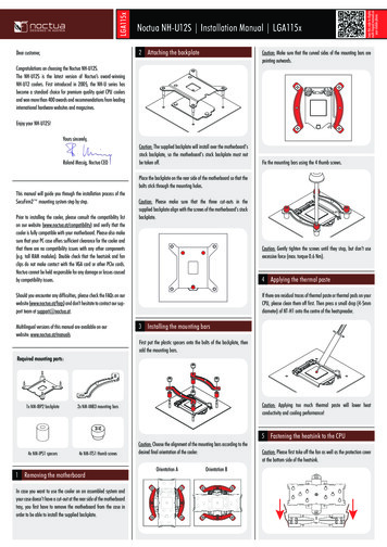
VERTICAL HI-RISE/STACK FAN COIL UNITSModel Series 39VH High Performance (88" High)MODELS:39VHZChilled/Hot Water (2-pipe).39VHZW Chilled & Hot Water (4-pipe).39VHZE Chilled Water & Electric Heat (2-pipe).39VHW Hot Water (2-pipe).AVERTICAL HI-RISE/STACK FAN COIL UNITSTYPES:C ConcealedM MasterE ExposedS SlaveSUPPLYOPENINGSWITH 5/8" (16)DRYWALL STOPA/B PairedDWThe 39VH Series Vertical Hi-rise Fan Coil Units aredesigned for quick installation, easy maintenanceand a wide range of customer configurations. Theseunits are designed to be "stacked" on each floor ofa building, either alone or in pairs This allows for asmall, space-saving footprint with one set of risersfor supply, return and drain lines. Flexible hosesallow for quick hook-up of water lines. The drain lineconnects with one ring clamp. Whether units aremounted behind drywall or are free standing in theroom, the front panel and supply grille provide easyaccess to all internal parts. Filters can be replacedin seconds. Most major components are removedby loosening four to six screws or crown nuts. The39VH family of products is designed to allow literallyhundreds of different options involving heating andcooling capacities, air flow, fittings, power needs, fancoil configurations and riser layouts.STANDARD FEATURES: Nine unit sizes ranging from 300 – 2100 CFM (142– 991 l/s). Outer casing constructed of 20 gauge (1.00)galvanized steel. Energy efficient three speed PSC motors withthermal overload protection. Fully lined with 1/2" (13) x 2 lb. / cu. ft. densitywater repellent insulation. Removable controls enclosure with hinged accessdoor. Easy access front panel and front supply grille forquick servicing. 1" (25) throwaway filter. AW Appliance White powder coat baked enamelfinish on supply grille(s) and return air panel.DWOPTIONALTOP SUPPLYAIR OPENINGDHA7/8" ICHEATRETURNOPENINGWITH5/8" (16)DRYWALLSTOPFAN88"(2235)69"(1753)VALVEPACKAGE /FLEX HOSESCOILSTANDARDFILTEROPTIONALOUTSIDEAIR DAMPER4 " (102) DIA.4 1/2" (114)**DRYWALL DIMENSIONSLAB TO BOTTOMOF RETURN PANEL(NOT SHOWN)CLEARANCE IS 3/4" (19)P. TRAP4 1/2" (114)5 1/2" (139)4" (102)Dimensional DataUnitSizeFootprintAxBSupply GrilleNominal DW x DHFilter SizeWidth x Height3, 5, 6 18 x 18 (457 x 457)16 x 10 (406 x 254) 13 1/8 x 16 3/4 (333 x 425)8, 10 20 x 20 (508 x 508)18 x 10 (457 x 254)15 1/2 x 24 (394 x 610)12, 15 24 x 24 (610 x 610) 22 x 10 (559 x 254)18 1/2 x 29 (470 x 737)COIL OPTIONS:2-pipe System:4-pipe System:19, 21 30 x 24 (762 x 610) 28 x 10 (711 x 254)24 1/2 x 29 (622 x 737) 1 Row HW only. 3/1 CW/HW Rows. 2 Row HW only. 3/2 CW/HW Rows.3-SPEED ECM / EPIC ECM MOTOR OPTION: 3 Row C/HW. 4/1 CW/HW Rows. 3-Speed ECM Motor: Nine unit sizes ranging from 300 – 2100 4 Row C/HW. CFM (142 – 991 l/s). EPIC ECM Motor: Four unit sizes (6, 10, 15, 19) ranging from 600– 1900 CFM (283 – 897 l/s). Wider turndown ratio. Significant energy savings. Variable Air Volume capability.A4
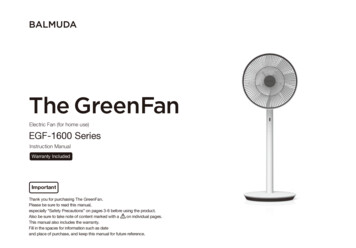
VERTICAL HI-RISE/STACK FAN COIL UNITSModel Series 39L Low Profile (80" high)MODELS:39LZ39LZW39LZE39LWChilled/Hot Water (2-pipe).Chilled & Hot Water (4-pipe).Chilled Water & Electric Heat (2-pipe).Hot Water (2-pipe).OPTIONALTOP SUPPLYAIR OPENINGDWAATYPES:C ConcealedM MasterS SlaveDWDHCONTROLSENCLOSURE3-SPEED ECM / EPIC ECM MOTOR OPTION: 3-Speed ECM Motor: Nine unit sizes ranging from300 – 2100 CFM (142 – 991 l/s). EPIC ECM Motor: Four unit sizes (6, 10, 15, 19)ranging from 600 – 1900 CFM (283 – 897 l/s). Significant energy savings. Variable Air Volume capability.FAN80"(2032)61"(1549)VALVEPACKAGE /FLEX HOSESCOILOPTIONALOUTSIDEAIR DAMPER4" (102) DIA.4 1/2" (114)**DRYWALL DIMENSIONSLAB TO BOTTOMOF RETURN PANEL(NOT SHOWN)CLEARANCE IS 3/4" (19)COIL OPTIONS:4-pipe System: 3/1 CW/HW Rows. 3/2 CW/HW Rows. 4/1 CW/HW Rows.OPTIONALELECTRICHEATRETURNOPENINGWITH5/8" (16)DRYWALLSTOPSTANDARD FEATURES:2-pipe System: 1 Row HW only. 2 Row HW only. 3 Row C/HW. 4 Row CW.7/8" (22)DWDH Nine unit sizes ranging from 300 – 2100 CFM (142– 991 l/s). Outer casing constructed of 20 gauge (1.0)galvanized steel. Energy efficient PSC motor with thermal overloadprotection. Fully lined with 1/2" (13) x 2 lb. / cu. ft. densitywater repellent insulation. Removable controls enclosure with hinged accessdoor. Easy access front panel and front supply grille forquick servicing. 1" (25) throwaway filter. AW Appliance White powder coat baked enamelfinish on supply grille(s) and return air panel.7/8" (22)BVERTICAL HI-RISE/STACK FAN COIL UNITSThe 39L Series Low Profile Vertical Hi-Rise Fan CoilUnits are 8" (203) shorter than the standard modeland are designed for use in buildings with a smallerthan normal floor to floor height (e.g. 8 ft.). Thereduced height of the unit enables better access tothe rear risers for brazing. Other than the reducedheight, the 39L Series shares all of the featuresand benefits of the 39VH Series described on theprevious page.DHSUPPLYOPENINGSWITH 5/8" (16)DRYWALL STOPSTANDARDFILTERP. TRAP4 1/2" (114)5 1/2" (139)4" (102)Dimensional DataUnitSizeFootprintAxBSupply GrilleNominal DW x DHFilter SizeWidth x Height3, 5, 6 18 x 18 (457 x 457) 16 x 10 (406 x 254) 13 1/8 x 16 3/4 (333 x 425)8, 10 20 x 20 (508 x 508) 18 x 10 (457 x 254)15 1/2 x 24 (394 x 610)12, 15 24 x 24 (610 x 610) 22 x 10 (559 x 254)18 1/2 x 29 (470 x 737)19, 21 30 x 24 (762 x 610) 28 x 10 (711 x 254)24 1/2 x 29 (622 x 737)Dimensions are in inches (mm).A5
LOW BOY VERTICAL FAN COIL UNITSModel Series 39MU Low Profile Updraft DesignMODELS:39MUZ39MUZW39MUZE39MUWABChilled Water.Chilled and Hot Water.Chilled Water and Electric Heat.Hot Water (2-pipe).1" (25)DHDWVERTICAL HI-RISE/STACK FAN COIL UNITSThe 39MU Low Boy Vertical Fan Coil Unit product line isa compact design for concealed stand-alone applications(such as in a closet). The standard Updraft model featuresbottom return air entry and is raised off the floor by mountingon a platform. When the optional front panel return grille isselected, the unit may be floor mounted or mounted in a pipechase. The top discharge is designed for ducted connectionto a remote grille(s).The units are designed with a small space-saving footprintfor quick installation, easy maintenance and with a widerange of options and configurations. A removable front panelprovides easy access to all internal components.Flexible hoses allow for quick hook-up of water lines. Thedrain line connects with one ring clamp.LINE VOLTAGECONTROLSENCLOSURE6 1/2"(165)10 1/2"(267)2"(51)DISCHARGEAIRFLOWFANVALVEPACKAGE /FLEX HOSESOPTIONALFRONTRETURNGRILLESIZES: 3 - 10:33 1/2" (851)SIZES: 12 - 21:37 1/2" (953)HSTANDARD FEATURES: Nine unit sizes ranging from 300 – 2100 CFM (142 – 991 l/s). Outer case constructed of 20 gauge (1.0) galvanized steel. Energy efficient PSC motor with thermal overloadprotection. Fully lined with 1/2" (13) thick, 2 lb/cu. ft. density waterrepellent insulation. Controls enclosure with door interlock disconnect for safety. Easy access front panel for quick servicing. 1" (25) throwaway filter. Galvanized steel insulated drain pan. Factory installed P-Trap.HW, CWOR CW/HWCOILIHFILTERP. TRAP4" (102)RETURNAIRFLOWIWRHRWCOIL OPTIONS:2-pipe System: 1 Row HW only. 2 Row HW only. 3 Row C/HW. 4 Row C/HW.4-pipe System: 3/1 CW/HW Rows. 3/2 CW/HW Rows. 4/1 CW/HW Rows.3-SPEED ECM/EPIC ECM MOTOR OPTION: 3-Speed ECM Motor: Nine unit sizes ranging from 300 –2100 CFM (142 – 991 l/s). EPIC ECM Motor: Four unit sizes (6, 10, 15, 19) rangingfrom 600 –1900 CFM (283 – 897 l/s). Wider turndown ratio. Significant energy savings. Variable Air Volume capability.Dimensional DataA6AOpt. ReturnGrille NominalIW x IHUnitSizeFootprintAxBHeightHDischargeNominalDW x DHReturnOpeningRW x RH3, 5, 618 x 18 (457 x 457)55 (1397)16 x 10 (406 x 254)15 x 8 (381 x 203)16 x 15 (406 x 381) 13 1/8 x 16 3/4 (333 x 425)17 x 9 (432 x 229)Filter SizeWidth x Height8, 1020 x 20 (508 x 508)55 (1397)18 x 10 (457 x 254)18 x 21 (457 x 533)15 1/2 x 24 (394 x 610)12, 1524 x 24 (610 x 610)60 (1524)22 x 10 (559 x 254) 21 x 12 (533 x 305) 22 x 26 (559 x 660)18 1/2 x 29 (470 x 737)19, 2130 x 24 (762 x 610)60 (1524)28 x 10 (711 x 254) 27 x 12 (686 x 305) 28 x 26 (711 x 660)24 1/2 x 29 (622 x 737)
LOW BOY VERTICAL FAN COIL UNITSModel Series 39MU Low Profile Updraft DesignPOWER SUPPLY VOLTAGE:(Units without electric heat)Single Phase (60 Hz): 120, 208, 240 and 277V.ECM MOTOR: Ultra-high efficiency ECM fan motor with fuse protection. Variable Air Volume control with ECM/EPIC fan technology .AHINGED CONTROLSENCLOSUREACCESS DOOR 1" (25) MERV 8 pleated disposable filter.DISCHARGEAIRFLOW Remote mounted thermostat. Custom build sub-base.ELECTRIC HEAT SECTION:Power Supply Voltage:Single Phase, 60Hz: 120V 208V 240V 277VNOTE:Incompatible heater/motor voltage selections require eithera dual point power connection or a step-down transformer(consult Nailor).STANDARD FEATURES: Heater is installed on unit discharge. Controls enclosure incorporates a hinged door and isrecessed inside the heater unit. The enclosure is top mountedon updraft unit.HEATER10" (254)CONTROLSENCLOSUREFAN39MU UPDRAFT HEATER SECTIONHVERTICAL HI-RISE/STACK FAN COIL UNITSOTHER OPTIONS: Class A 80/20 Ni/Cr wire. Insulated coil element wrapper.Automatic reset high limit cut-outs (one per element).Single point electrical connection for entire fan coil unit.Fan interlock relay.Fan coil unit with electric heat is ETL Listed as an assembly.Door interlock disconnect switch.OPTIONS: Dust tight construction.Quiet contactors.Mercury contactors.Power circuit fusing.Toggle disconnect switch.Manual reset secondary thermal cut-out.Airflow safety switch.A7
VERTICAL HI-RISE/STACK FAN COIL UNITSModel Series 39VH & 39L Electric Heating Coils Construction Features,Selection and CapacitiesEngineered Comfort Electric Coils are tested with the fancoil in accordance with UL Standard 1995 and meet allrequirements of the National Electric Code and CSA. Unitsare listed and labeled by the ETL Testing Laboratory as anassembly. All controls are enclosed in a NEMA 1 electricalenclosure for easy access.AVERTICAL HI-RISE/STACK FAN COIL UNITSAll wiring for the motor and heater terminates in the enclosurefor single point electrical connection in the field. Each unit issupplied with a wiring diagram.Note: NEC requires a means to disconnect the heater powersupply within sight of or on the fan coil unit.Power Supply Voltage:Single Phase, 60Hz: 120V 208V 240V 277VRecommended Selection:STANDARD FEATURES: Controls enclosure incorporates a hinged door and isrecessed inside the unit. To access the controls enclosureremove the front panel. Automatic reset high limit thermal cut-outs. Magnetic contactors per stage on fan coils with DDC orelectronic controls. Class A 80/20 Ni/Cr wire. Control voltage transformer (Class 2) for DDC andelectronic fan coils.Optional Accessories: Toggle disconnect switch Main Switch Door interlocking disconnect switch Drain pan heat switch Quiet contactors Mercury contactors Power circuit fusing Dust tight control enclosure Manual reset secondary high limit Airflow safety switchA8Max.The table below is a quick reference guide, to illustrate therelationship between electrical power supply, heater capacityin kilowatts and fan coil unit size that are available. Fan coils are available with 1 stage of heat as standard(2 stages of heat are optional with digital controls). Aminimum of 0.5 kW per stage is required. Voltage and kilowatt ratings are sized so as not to exceed48 amps, in order to avoid the NEC code requirement forcircuit fusing. A minimum airflow of 70 CFM (33 l/s) per kW is requiredfor any given fan coil in order to avoid possible nuisancetripping of the thermal cut-outs. Discharge air temperature should not exceed 115 F(46 C).Useful Formulae:CFM x TkW 3160 T kW x 3160CFM1ph.Amps kW x 1000voltsTested and approved to thefollowing standards:UL1995, 4th. ed.CSA C22.2No. 236-11.Electric Heat Maximum 9911.521220010383.59911.51-6-20
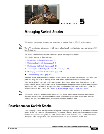
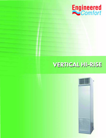
VERTICAL HI-RISE/STACK FAN COIL UNITSElectric Heating Coils Application GuidelinesThe maximum approved discharge air temperature for anyEngineered Comfort Fan Coil Units with supplemental heatis 120 F (49 C). No heater should be applied to exceed thistemperature.Electric Heater SelectionTo properly select an electric heater, three things must bedetermined: the heat requirement for the room, the enteringair temperature and the desired discharge air temperature.The heat requirement for the room is the sum of the heatloss calculation and the amount of heat required to raise theentering air temperature to the desired room temperature.Usually, the second item is small compared to the first for fancoil units in a return air plenum. MBH can be converted to kWby using the chart or by calculation. There are 3413 BTU’s in1 kW. If using the chart, find the MBH on the left scale, thenmove horizontally to the right and read kW.Next, the desired discharge air temperature should beascertained. This will depend on the type of diffusers thatare in the room.kW x 3160 T (Discharge air temp – Inlet air temp.) FAAssuming 70 F (21 C) supply air temperature to the heater,the room airflow can be selected directly from the chart. Startat the left at the design kW. Move horizontally to the desireddischarge air temperature. Then, move vertically down to theCFM at the bottom of the chart.The kW can be selected directly from the chart. Start at thebottom with the design CFM into the room. Move verticallyup to the line that represents the desired discharge airtemperature. Then, move left to the kW.The discharge air temperature can also be selected directlyfrom the chart. Start at the bottom with the design CFM intothe room. Move to the left side of the chart and find the designkW. Move horizontally and vertically into the chart until thelines intersect. The intersection will be the desired dischargeair temperature. Interpolation between the curves is linear.Heater Selection ChartAssuming 70 F inlet air temperature at heater.170115 F50160110 F45150140105 F40130120100 F35110908070605040302010095 F30100kWDiffusers in the center of the room blend their dischargeair as it crosses the ceiling. Discharge air temperatures inthis application can be as high as 105 F (41 C) and stillbe effective. However, if the return air grilles are in thedischarge air pattern, the warm air will be returned to theplenum before it heats the room. Again, the air temperatureneeds to be blended down to an acceptable temperaturethat can be forced down into the occupied space by thetime the air gets to the walls. Discharging warm air into theroom at temperatures above 105 F (41 C) usually will set upstratification layers and will not keep the occupants warm ifthere is a ceiling return because only the top 12" – 24" (300– 600 mm) of the room will be heated.CFM VERTICAL HI-RISE/STACK FAN COIL UNITSWhen considering the capacity and airflow for the heater,discharge air temperature can be an important factor.Rooms use different types of diffusers, and they are intendedto perform different functions. Slots that blend the air at theglass and set up air curtains within the room, must be able toblow the air very low in the room. Hot air will be too buoyantto be effective in this case. Discharge air temperaturesfor this application should be in the 85 – 90 F (29 – 32 C)maximum range.The desired heating airflow for the room can then becalculated using the following equation:MBHDischarge Air Temperature2590 F2085 F1580 F1050050010001500 2000 2500AIRFLOW, CFM300035004000Diagonal lines are constant output temperature.A9
VERTICAL HI-RISE/STACK FAN COIL UNITSModel Series 39VH 2 or 4-pipe System with Full Face CoverAFront PanelSupply GrilleEReturn Air GrilleFAlternate SideGrille LocationVERTICAL HI-RISE/STACK FAN COIL UNITSGFan AssemblyHCW/HW CoilJDrain PanKFilterASUPPLYDRAINRETURNPFan AccessPanelMControlsEnclosureM-1 Electric Heat(Opt.)NRisers (Opt.)PElectricalKnock-outRControl ValveSFlex Hose withShut-off ValveTP-TrapUQuarter TurnLatchesVRiser Chase(Opt.)B3" (76)3" (76)2 PIPE SYSTEMTOP VIEW WITH SHROUD2 PIPE RISERCONFIGURATION(REFERENCE)AdjustableCeiling Shroudfor exposedunits (Opt.)3 5/8" (93)6" (152)3 5/8" (93)4 PIPE RISERCONFIGURATION(REFERENCE)4 PIPE SYSTEMTOP VIEW WITH SHROUD1"(25)1"(25)3" /8" (22)KNOCK OUTRETURN/SUPPLYRISERDETAILGL56 1/2"(1435)STD.88"(2235)6 5/8" T PANELWN2 PIPE SYSTEMFRONT VIEWFLOORTOFLOOR 2" (51)40"(1016)KK-1W Sub-Base (Opt.)X6"(152)CW RETURNCW SUPPLYDRAINHW RETURNHW SUPPLYA1"(25)K-1 Filter RackL6"(152)BCDASREQ'DNSIDE VIEW4 PIPE SYSTEMFRONT VIEWModel SizesUnitSizeNominal AirflowRange (CFM)Nominal CoolingCapacity (MBH)FootprintA x B inches (mm)3, 5, 6300, 500, 60015, 18, 2218 x 18 (457 x 457)8, 10800, 100030, 3420 x 20 (508 x 508)12, 151200, 150042, 4624 x 24 (610 x 610)19, 211900, 210060, 6530 x 24 (762 x 610)NOTES:All units are designed to accept both two- and four-pipe riser configurations. Risers can be located on the right side, left side or backof the unit. Supply grilles can be located on the front right side or left side of the unit. Return grilles are located on the front of the unit.Dimensions are in inches (mm).A10
VERTICAL HI-RISE/STACK FAN COIL UNITSModel Series 39VH Piggyback AssemblyDRAIN RISERCHILLED WATER RETURN RISERCHILLED WATER SUPPLY RISERB7/8" (22) DIA.ELECTRICALKNOCK-OUTSAAVERTICAL HI-RISE/STACK FAN COIL UNITSSEPARATESUPPLY GRILLE(STD.)88"(2235)FURR DOWNFRONT PANELWITHSTANDARD RAGRILLE7" (178)BVARIESB DIMENSIONx 2 7" (178)AType A/B Paired Unit Side by Side AssemblyTOPOUTLET7/8" (22) DIA. KNOCK-OUTS(2 PER UNIT REQ.)AABFULL COVERPANEL WITHSTANDARDRA GRILLEBFULL COVERPANEL WITHSTANDARDRA GRILLEAND INTEGRALSUPPLY RA GRILLESTANDARD GRILLE(ONE PER UNIT)SIDE BY SIDE ASSEMBLYFOUR PIPE RISER5/8" (16) TYPE "X"GYPSUM BOARD UL LISTEDAS NOT LESS THAN 1HOUR FIRE RETARDANTASTM C 1396/C 36SPACER PLATE W/OPTIONAL MOUNTEDTHERMOSTATSIDE BY SIDE ASSEMBLYA11
VERTICAL HI-RISE/STACK FAN COIL UNITSModel Series 39VH & 39L Unit Configurations for Riser Location & DischargeGrille ArrangementSINGLE SIDE SUPPLYDOUBLE SIDE SUPPLYUNIT DESIGNATIONSBACKARB - DFRB - DRRB - DLRB - DFLRB - DFRRB - DLRLEFTTOPOPTIONALRISERCHASE(SEE NOTES)RIGHTVERTICAL HI-RISE/STACK FAN COIL UNITSFRONTRL - DRRL - DBRR - DLRR - DFRL - DFRR - DBTOP AND SINGLE SIDE SUPPLYRB - DFTRB - DRTRL - DFRRL - DRBRR - DLBRR - DFLRL - DFBRR - DFBTOP AND DOUBLE SIDE SUPPLYRB - DLTRB - DFRTRB - DFLTRB - DLRTEXAMPLE: RB-DFXXX-VRRISER LOCATION:RB BACKRR RIGHTRL LEFTDISCHARGE GRILLE LOCATION 1:DF FRONTDT TOPDL LEFTDR RIGHTDISCHARGE GRILLE LOCATION2, 3 & 4:L LEFTB BACKR RIGHTT TOPOUTSIDE AIR LOCATION:VL LEFTVR RIGHTSUPPLY AIRFLOWRL - DRTRL - DBTRL - DFTRR - DFLTRR - DLBTRR - DFBTRETURN AIRFLOWNOTES:1. Return air panel and unit accessare always on front of unit.RR - DLTRR - DFTRR - DBTTOP ONLY SUPPLYRB - DTRL - DTRR - DFBLRL - DFRTRL - DFBTTOP AND TRIPLE SIDE SUPPLYRR - DTTRIPLE SIDE SUPPLYRB - DFLRRL - DRBTRL - DFBRRB - DFLRTRR - DFBLTRL - DFBRT2. A sight and sound baffle isprovided on double side supplyunits with a directly opposite grillelocation. Not available with triplesupply or top outlets.3. Opposed blade damper on onesupply grille for units with doublesupply and two grilles for triplesupply outlets.4. Last optional character refers toventilation outside air location.Options are left or right side onlyand must be opposite to any left orright riser.5. Type C Stand-alone units shownwith optional riser chase. Riserchase not available on Type MMaster units. Type A units must bemated to Type B units. For TypeB and S units, first characterreferences connection locationonly (risers are on Type A or Munit respectively).6. Exposed models are availableas standard with RB Riser Backlocation only.A12
VERTICAL HI-RISE/STACK FAN COIL UNITSModel Series 39VH & 39LTypical Stand-alone and Paired Unit ConfigurationsTYPE C - CONCEALED (STAND-ALONE):RR - DFBRB - DFARR - DFRL - DFVERTICAL HI-RISE/STACK FAN COIL UNITSTYPE A/B - PAIRED:Type ARR - DFType BRR - DFType ARR - DFLRoom 2Type BRL - DFRClosetClosetType ARB - DFType BRB - DFRoom 1Room 1"Side-By-Side"Occupancy ARoom 2"Piggyback"*Room 1Type BRB - DFType ARB - DF"Piggyback"Room 2Room 2Room 1Room 2*TYPE E - EXPOSED:RB - DFType BRB - DFRRoom 1"Piggyback"*Room 1Type ARB - DFLOccupancy B"Piggyback"*TYPE M/S - MASTER / REMOTE SLAVE:Type MRB - DFRoom 1Type SRB - DFRoom 2Exterior WallField Drywall (sheetrock)Interior Wall Partition or SeparationEng. Comfort "Type X" Gypsum wallboardField installed pipingSupply AirReturn AirAvailable in one-hour, UL fire-ratedconstructionCustom side-by-side exposedinstallationNOTES:LEGEND:*Room 2SIGHT AND SOUNDBAFFLES PROVIDEDAS REQUIREDA Master Unit (with risers)B Slave Unit (with riserconnection)1. Above are just a few of the manyarrangement possibilities.2. For other combinations, see proceedingpage and ensure compatibility.3. Non-fire rated Paired units are standard(single wallboard) UL 1 Hour LabelFire-rated is an option (double "Type X"wallboard).A13
VERTICAL HI-RISE/STACK FAN COIL UNITSModel Series 39VH Standard Front Return Air Panel for Type C ConcealedUnits Separate Supply GrilleOPTIONALRA FILTER GRILLESTANDARD RA GRILLEAFURRED IN UNIT PANEL(CONCEALED DRYWALL)1/4 - TURNFASTENERSVERTICAL HI-RISE/STACK FAN COIL UNITSOPTIONAL PANELMOUNTED THERMOSTATKNOCK-OUT 56 1/2" (1435)FROM BOTTOM OF UNITSTANDARD.ADA OPTION IS 48" (1219).73 1/2"(1867)1/4 - TURNFASTENERSIWIWFIHIHFTOEPLATEW3/4" (19)WOptional Front Return Air Panels for Type C Concealed UnitsExtended Cover (with integral front supply grille where specified)STANDARD RA GRILLEWITH FRONT SUPPLY GRILLESTANDARD RA GRILLEOPTIONAL RA FILTER GRILLEWITH FRONT SUPPLY GRILLEOPTIONALRA FILTER GRILLEFURRED IN UNIT PANEL(CONCEALED DRYWALL)1/4 - UT56 1/2" (1435)FROM BOTTOMOF UNITSTANDARD.ADA OPTIONIS 48" (1219).87 1/4"(2216)IWFIWIHIHFTOEPLATEWA143/4" (19)
VERTICAL HI-RISE/STACK FAN COIL UNITSModel Series 39VH Standard Front Return Air Panels for Type C ConcealedUnits Extended Full Length Cover (with integral front supply grille wherespecified)STANDARD RA GRILLEWITH FRONT SUPPLY GRILLESTANDARD RA GRILLEOPTIONAL RA FILTER GRILLEWITH FRONT SUPPLY GRILLEOPTIONALRA FILTER GRILLEEXPOSED UNITPANELAVERTICAL HI-RISE/STACK FAN COIL UNITS1/4 - UT56 1/2" (1435)FROMBOTTOMOF UNITSTANDARD.ADA OPTIONIS 48" (1219).87 1/4"(2216)IWIWFIHIHFTOEPLATE1 3/16" (30)WDimensions:NOTES:Optional ReturnAir Filter GrilleIWF x IHFUnitSizeWStandard ReturnAir GrilleIW x IH3, 5, 618 (457)16 x 15 (406 x 381)14 x 15 (356 x 381)8, 1020 (508)18 x 21 (457 x 533)16 x 21 (406 x 533)12, 1524 (610)22 x 26 (559 x 660)20 x 26 (508 x 660)19, 2130 (762)28 x 26 (711 x 660)26 x 26 (660 x 660)1. All front panels feature a high free area louvered return grille.2. A removable face filter return grille is available. This optioneliminates having to remove the front panel for easier filterreplacement.3. The standard reduced height front panels are designed for(furred-in) unit installation concealed by drywall [ 1/2" to 5/8"(13 to 16)] only.4. Optional full cover front panels
VERTICAL HI-RISE/STACK FAN COIL UNITS Units are available with chilled / hot water coils and electric heat. All units are certified by AHRI and listed by ETL and display the AHRI and ETL symbols. Coil options allow for 3 to 5 row chilled water and 1 or 2 row hot water. 5 rows total in combination. The units are shipped completely