Transcription
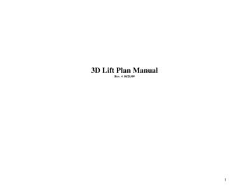
WIDE SPAN SHELVINGI N S TA L L AT I O NPAGE 1 OF 10ASY 061I N S T R U C T I O N SPAGE 2-3PARTSIDENTIFICATIONNOTE!This publication is intended to be a generic installationinstruction for Madix Wide Span, and may possibly besubject to change as required by local building codes.consult the building inspection department at job site.PAGE 4-5BASICINSTALLATIONPAGE 6-7INSTALLATION OFEXTRASPAGE 8LOADCAPACITYPAGE 9SAFETYPAGE 10ANCHORINGTOFLOORP. O . B O X 7 2 9 / T E R R E L L , T E X A S 7 5 1 6 0 / 9 7 2 . 5 6 3 . 5 7 4 4 / 8 0 0 . 7 7 6 . 2 3 4 9P. O . B O X 1 7 7 / G O O D W A T E R , A L A B A M A 3 5 0 7 2 / 2 0 5 . 8 3 9 . 6 3 5 4 / 8 0 0 . 6 3 3 . 6 2 8 2REV05
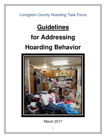
WIDE SPAN SHELVINGP A R T SLIGHT DUTY LDREGULAR DUTY RDHEAVY DUTY HDLIGHTDUTYREGULARDUTYPAGE 2 OF 10ASY 061I D E N T I F I C A T I O ONSDeck SupportsBeamsActualFrame Actual Beam LengthDepth Length Length Inside ofBrackets18"20"48" 48 3/16"24"26"60" 60 3/16"30"32"72" 72 3/16"36"38"84" 84 3/16"42"44"96" 96 3/16"48"50”-LIGHT DUTY LDREGULAR DUTY RDHEAVY DUTY MEDEPTHREGULAR DUTY RDHEAVY DUTY HDFRAMEDEPTHRDWSFWIDE SPANFRAMEFRAMEHEIGHTFRAME DIMENSIONSFrame Actual Frame ActualDepth Depth Height Height18"20"48"48 8"50"108" 108"120" 120"P. O . B O X 7 2 9 / T E R R E L L , T E X A S 7 5 1 6 0 / 9 7 2 . 5 6 3 . 5 7 4 4 / 8 0 0 . 7 7 6 . 2 3 4 9P. O . B O X 1 7 7 / G O O D W A T E R , A L A B A M A 3 5 0 7 2 / 2 0 5 . 8 3 9 . 6 3 5 4 / 8 0 0 . 6 3 3 . 6 2 8 2REV05
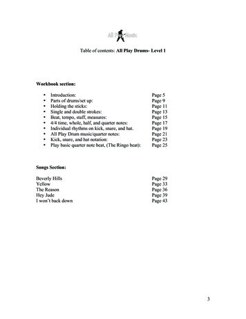
WIDE SPAN SHELVINGP A R T SREGULAR DUTY RDHEAVY DUTY HDFRAMEDEPTHSEALED SUNSEALED URDWSDWIDE RE GRIDDECKFRAMEDEPTHWIRE GRIDPIECELENGTHWIRE GRID DECKS, andFLOW THROUGH DECKS.dimensionsFrame Actual Piece ActualDepth Depth Length Length18" 17 3/4" 24" 23 3/4"24" 23 3/4" 36" 35 3/4"30" 29 3/4" 48" 47 3/4"36" 35 3/4"42" 41 3/4"48" 47 3/4"-ASY 061I D E N T I F I C A T I O NPARTICLE BOARD DECKS.dimensionsFrame Actual Beam ActualDepth Depth Length Length18"18"48" 47 29/32"24" 23 29/32" UBEAMLENGTHPAGE 3 OF 10GRIDSIZE.3"o.c.-3NOMINAL PIECELENGTHFLOWTHROUGHNOMINALFRAMEDEPTHFTWSDWIDE SPANDECKNOMINAL PIECELENGTHFLOW THROUGHWIRE GRID and FLOW THROUGH PIECELENGTHS RUN PARALLEL TO BEAM LENGTHSBEAM COMBINATIONS OF # OF DECKLENGTH PIECE LENGTHS SUPPORTS36"36"248"48"260"24" plus 36"472"36" plus 36"484"36" plus 48"496"48" plus 48"4P. O . B O X 7 2 9 / T E R R E L L , T E X A S 7 5 1 6 0 / 9 7 2 . 5 6 3 . 5 7 4 4 / 8 0 0 . 7 7 6 . 2 3 4 9P. O . B O X 1 7 7 / G O O D W A T E R , A L A B A M A 3 5 0 7 2 / 2 0 5 . 8 3 9 . 6 3 5 4 / 8 0 0 . 6 3 3 . 6 2 8 2REV05
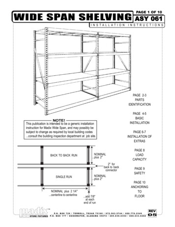
WIDE SPAN SHELVINGB A S I C1Snap chalklines on flooras shown for shelvinglayout. See diagram onpage one for dimensions.1ENDLINEPAGE 4 OF 10ASY 061I N S T A L L A T I O NAISLELINE2 Raise first frame tovertical position and installfirst beam.frame will nowstand alone.NOTE! If floor anchors orextension frames are to beused, they should beinstalled prior to raisingframes to the verticalposition.see pages 5-6.3243 Raise second frame tovertical and install free endof first beam. installsecond beam on oppositeside.4 Install upper beams atdesignated levels.TOP OFFRAMEUPRIGHTDART CLIPWDC-50.pack of 50BOTTOM OFFRAMEUPRIGHTRETAINERPINWSREP55 If using Dart Clips:Press dart clips throughbeam bracket and uprighton under side of beam asshown. Insert one dart clipat each end of all beams.Insert dart clip from insideupright if using LD beams.If using Retainer Pins:Insert one leg of a retainerpin through beam bracketand upright. Insert one pinat each end of all beams.Insert dart clip verticallyif using LD beams.NOTE: Retainer pins and dart clips serve the same purpose - to retain beamconnectionsIMPORTANT: ANY BEAM USED AS A PRODUCT RETAINER MUST BEBOLTED THROUGH BOTH UPRIGHTS.P. O . B O X 7 2 9 / T E R R E L L , T E X A S 7 5 1 6 0 / 9 7 2 . 5 6 3 . 5 7 4 4 / 8 0 0 . 7 7 6 . 2 3 4 9P. O . B O X 1 7 7 / G O O D W A T E R , A L A B A M A 3 5 0 7 2 / 2 0 5 . 8 3 9 . 6 3 5 4 / 8 0 0 . 6 3 3 . 6 2 8 2REV05
WIDE SPAN SHELVINGB A S I C6 Repeat assemblysequence with remainingframes, beams and dartclips/retainer pins.NOTE! If back to back runsare being installed, seepage 6 for back to backconnectors.7Holding the deck supportat an angle to the beam,squeeze the open side andinsert into the beam, thenswing the free end aroundto the opposite beam,squeeze the open side andinsert into the beam.PAGE 5 OF 10ASY 061I N S T A L L A T I O NDECK SUPPORTS. QUANTITY & LOCATIONwood decks.three deck supportsall decks.two deck supports87wire grid and flow through decks.four deck supports98 Squeeze the open side ofthe deck support at eachend just inside the beamand rotate upwards asshown.109 Correct installed positionwill look like this.seeabove for quantity of decksupports per beam length.10 Repeat with theremaining deck supports inthe shelving run.11 Install all decks in theshelving run.11P. O . B O X 7 2 9 / T E R R E L L , T E X A S 7 5 1 6 0 / 9 7 2 . 5 6 3 . 5 7 4 4 / 8 0 0 . 7 7 6 . 2 3 4 9P. O . B O X 1 7 7 / G O O D W A T E R , A L A B A M A 3 5 0 7 2 / 2 0 5 . 8 3 9 . 6 3 5 4 / 8 0 0 . 6 3 3 . 6 2 8 2REV05
WIDE SPAN SHELVINGI N S T A L L A T I O N12 The first sections of theback to back run should beerected with beams at topand bottom of the fourframes. Locate theconnectors just below the topbeams and just above thebottom beams. Secure withthe fasteners as shown.13 Repeat with the remainingsections.14 Install all intermediate beamsB16 Insert connector into frameframe with providedfasteners.remove the stop.18 Repeat above with the 2ndupright of the frame.19 Lower upper frame ontoconnectors and securethrough the sixth hole upfrom the joint.E X T R A SA .indicates item, where used.CFRAMECONNECTORSWSFC-2with flat center of connectorfacing the slotting.17 Screw connector to lowerO FWSBBC-2-24 HARDWARE PACK #7200-079QTY.ITEM DESCRIPTION1/4 - 20 x 2 1/4" carriage boltA 481/4 - 20 wing nutB 4815 In the sixth square holefrom the top of the lowerframe, insert a stop toprevent the connector fromdropping to the floor.ASY 061BACK TO BACKCONNECTORWSBBC-2-24Aas required, then install athird connector as close aspossible to the mid-point ofthe frames. Complete theshelving run with the decksupports and decks.PAGE 6 OF 10CDDWSFC-2 HARDWARE PACK #7200-078QTY. ITEM DESCRIPTION1/4 - 20 x 2" Phillips truss head machine screwC 41/4 - 20 hex nutD 4C .indicates item, where used.P. O . B O X 7 2 9 / T E R R E L L , T E X A S 7 5 1 6 0 / 9 7 2 . 5 6 3 . 5 7 4 4 / 8 0 0 . 7 7 6 . 2 3 4 9P. O . B O X 1 7 7 / G O O D W A T E R , A L A B A M A 3 5 0 7 2 / 2 0 5 . 8 3 9 . 6 3 5 4 / 8 0 0 . 6 3 3 . 6 2 8 2REV05
WIDE SPAN SHELVINGI N S T A L L A T I O NFLOOR ANCHOR WSFA-2PAGE 7 OF 10ASY 061O FE X T R A SNOTE! IF FRAME HEIGHT, OR TOTAL HEIGHT OF CONNECTED FRAMES, IS MORE THAN SIX TIMES THEFRAME DEPTH .FRAMES MUST BE SECURED WITH FLOOR ANCHORS.20 Insert floor anchors into thebottom of each frame. Theywill only insert at 45O to theframe. Make sure thatanchors are inserted so thatthey will not project intoaisles or cross aisles.21 Follow directions on page4 to step 6, except do notinstall dart clips on bottombeams. Secure beams toframes through the flooranchor as shown. The screwwill go through at one of thetwo locations, depending onthe beam size.22 Check run alignment tochalkline prior to drilling floorfor expansion bolts. Due tovarying floor conditions,expansion bolts must beordered separately. If theywere not ordered initially, butare required, see page 8 toorder from Madix orpurchase locally.20ACB21LEVELING SHIMWSLS-10CTen pack of galvanizedshims.dimpledto fit in bottom of upright andmaintainstacking interlock.WSFA-2 HARDWARE PACK #7200-080QTY. ITEM DESCRIPTION1/4 - 20 x 2 1/2" round head machine screwA 21/4 - 20 hex nutB 21/4" flat washerC 2A .indicates item, where used.TOP CAPWSTC - -CLPacks of 4 or 48 clearplastic top caps, two perframe. Tap into top ofeach frame upright.P. O . B O X 7 2 9 / T E R R E L L , T E X A S 7 5 1 6 0 / 9 7 2 . 5 6 3 . 5 7 4 4 / 8 0 0 . 7 7 6 . 2 3 4 9P. O . B O X 1 7 7 / G O O D W A T E R , A L A B A M A 3 5 0 7 2 / 2 0 5 . 8 3 9 . 6 3 5 4 / 8 0 0 . 6 3 3 . 6 2 8 2REV05
WIDE SPAN SHELVINGLOADSPAGE 8 OF 10ASY 061AFETYHAND STACK ONLY!POWERED FORK TRUCKSOR STACKERS ARE NOTRECOMMENDED FOR USEON WIDE SPAN SHELVINGFRAME LOADINGFrame loading is the vertical load, measured in pounds, that can be applied on any Wide span frame.Each Wide span frame will bear ONE HALF OF THE LOAD ON EACH BEAM PAIR that it supports.ALL FRAMES HAVE 10,000 POUND LOAD CAPACITY!!Height to Depth Ratio:Ratio should not exceed 6 to 1measuring to the top of topmost load. If ratio exceeds6 to 1 the constraint can beovercome with properanchoring or external b racingof the rack structure.CONSULT YOUR STRUCTURALENGINEER FOR SOLUTIONS.MAXIMUMBEAMLOADCAPACITY.PERBEAMPAIR Based on evenlydistributed loads Based on 96”beam length, allframe widthsBEAMLENGTH48"60"72"84"96"LIGHT REGULAR HEAVY # OF DECKDUTYDUTYDUTY SUPPORTS1000 # 1600 #3000 #21000 # 1600 #3000 #31000 # 1600 #3000 #31000 # 1600 #3000 #31000 # 1600 #3000 #3P. O . B O X 7 2 9 / T E R R E L L , T E X A S 7 5 1 6 0 / 9 7 2 . 5 6 3 . 5 7 4 4 / 8 0 0 . 7 7 6 . 2 3 4 9P. O . B O X 1 7 7 / G O O D W A T E R , A L A B A M A 3 5 0 7 2 / 2 0 5 . 8 3 9 . 6 3 5 4 / 8 0 0 . 6 3 3 . 6 2 8 2REV05
WIDE SPAN SHELVINGS A F E T YD U R IN GPAGE 9 OF 10ASY 061I N S TA L L AT IO NGENERAL1. Contact the local building department prior to starting installation to check on any restrictions.2. Only parts and accessories produced or supplied by Madix are covered by Madix warranty.3. Installation sequence must be followed exactly for assembly and leveling.4. Under no circumstances should damaged parts be used.5. Do not use shelving parts or accessories for any purpose other than originally intended.6. Installation instructions with product load ratings are included with each order and must be followedcarefully.7. Merchandisers must be made aware of possible overloading as specified in load ratings. If you do notreceive these, please contact your sales or customer service representative.8. Initial installation or relocation of Madix gondola, wall or racking fixtures should be supervisedexclusively by qualified personnel.RACKING. FRAMES / BEAMS9. Observe all prohibitions in the installation instructions on the use of powered lifts.10. A minimum of four people are required to erect frames taller than 8’.11. Be sure all beams or accessories are completely seated and locked or secured in frame slotting.12. Ladders, if used, should be at least frame height.13. Never stand on lower beams to install upper beams.14. Do not walk on decks, especially wire grid.15. Never try to move a completed racking run, especially if merchandised.P. O . B O X 7 2 9 / T E R R E L L , T E X A S 7 5 1 6 0 / 9 7 2 . 5 6 3 . 5 7 4 4 / 8 0 0 . 7 7 6 . 2 3 4 9P. O . B O X 1 7 7 / G O O D W A T E R , A L A B A M A 3 5 0 7 2 / 2 0 5 . 8 3 9 . 6 3 5 4 / 8 0 0 . 6 3 3 . 6 2 8 2REV05
WIDE SPAN SHELVINGA N C H O R I N GT OPAGE 10 OF 10ASY 061T H EF L O O REXPANSION BOLTS FOR FLOOR ANCHORS.50 expansion bolts, 1/2”-13 x 3 1/2” POWERS/ Power-Stud SD2 concrete anchors orother ICC (ICBO) approved expansion bolts.SFA-EB-12-334:See below for other ICC (ICBO) approved expansion bolts which may be used.NOTE! The expansion anchors provided by Madix for floor anchoring at this site have been supplied by one ofthe firms listed below. All the anchors have been tested and approved as stated by the following ICC (ICBO) reportnumbers and all are manufactured in the United States or Canada. If the anchors are not provided by Madix andfield substitution other than listed be proven, Madix cannot be held responsible. Should verification be required,call Madix Customer Service at: 800.776.2349. . . . . . . . . . . . . . . . . . . . . . . . . . . . . . . . . . . . . . . . . . . . . . . . . . . . . . . . . . . . . . . . . . . . . . . . .ICC (ICBO) #COBRA ANCHORS CORP., Parawedge concrete anchors . . . . . . . . . . . . . . . . . . . . . . . . . . . . .ER-2350 S1DIVERSIFIED FASTENING SYSTEMS, DFS Wedge anchor . . . . . . . . . . . . . . . . . . . . . . . . . . .ER-4194 S1GUNNEBO FASTENING CORP.,Drop-in concrete anchors . . . . . . . . . . . . . . . . . . . . . . . . . . . . .ER-3219 S1HILTI, INC., Kwik-bolt-TZ concrete anchors . . . . . . . . . . . . . . . . . . . . . . . . . . . . . . . . . . . . . . . .ESR-1917MKT FASTENING, High Load Anchor SZ . . . . . . . . . . . . . . . . . . . . . . . . . . . . . . . . . . . . . . . . . . . .AC-193ITW RAMSET/RED HEAD, ITW Ramset stud, Trubolt wedge concrete anchors . . . . . . . . . . .ESR-2251MARKSMAN MANUFACTURING CO., Thunderstud wedge and sleeve anchor . . . . . . . . . . . . . .ER-2713 S1POWERS FASTENING INNOV., Power-Stud SD2 concrete anchors . . . . . . . . . . . . . . . . . . . . .ESR-2502WEJ-IT, Wej-it anchors bolt and ANKR-TITE wedge anchor . . . . . . . . . . . . . . . . . . . . . . . . . . . .ER-1825CYW, INC., POWER BULL, Wedge anchor . . . . . . . . . . . . . . . . . . . . . . . . . . . . . . . . . . . . . . . . . . . . . . . . . . . . . . . . . . . . . . .ESR-2254*Embedment must be minimum 5x bolt diameter.OTHER ICC (ICBO) APPROVED ANCHORING MATIERALS. not furnished by MadixPNEUMATIC OR POWDER-DRIVEN STEEL STUDS AND NAILSHILTI, INC., Hilti low velocity powder actuated or pneumatically driven fasteners . . . . . . . . . . . . . .ESR-1663ITW RAMSET/RED HEAD, Ramset Powder-Actuated and PowerPoint fasteners . . . . . . . . . . . . . .ESR-1799ADHESIVE/ EPOXY ANCHORSHILTI, INC., HIT-HY 150 Adhesive anchor system . . . . . . . . . . . . . . . . . . . . . . . . . . . . . . . . . . . . . ESR-2678ITW RAMSET/RED HEAD, ITW Red Head Epcon system Ceramic 6 epoxy anchors . . . . . . . . . ESR-3577P. O . B O X 7 2 9 / T E R R E L L , T E X A S 7 5 1 6 0 / 9 7 2 . 5 6 3 . 5 7 4 4 / 8 0 0 . 7 7 6 . 2 3 4 9P. O . B O X 1 7 7 / G O O D W A T E R , A L A B A M A 3 5 0 7 2 / 2 0 5 . 8 3 9 . 6 3 5 4 / 8 0 0 . 6 3 3 . 6 2 8 2REV#0102ECN#REVISION5- 13950 UPDATED TO CORRECT ANCHOR INFO5*14150 ADDED HEIGHT/DEPTH RATIOBYSAMCABDAT E1/7/1402/14/14035*16478 SHOWED LD BEAM DART CLIP ON PG 4TED06/29/15REV#0405ECN#REVISION5*18143 ADDED BOLTING REQ. TO PG 45*21426 UPDATED 1/2” - 13 BOLT, PG 10REV05BYDAT ENRDHER09/12/1605/14/19
WIDE SPAN SHELVING ASY 061 PAGE 1 OF 10 I N S T A L L A T I O N I NSTRUC T I O N S P.O. BOX 729 / TERRELL, TEXAS 751 60 / 972.563.5744 / 800.776.2349 P.O. BOX 177 / GOODWATER, ALABAMA 350 72 / 205.839.6354 / 800.633.6282 REV 05 NOTE! This publication is intended to be a generic installation instruction for Madix Wide Span, and may possibly be