Transcription
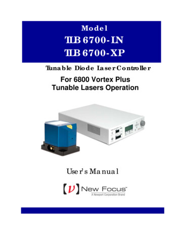
ModelTLB 6700-LNTLB 6700-XPTunable Diode Laser ControllerFor 6800 Vortex PlusTunable Lasers OperationUser’s Manual
iiPrefaceEU Declaration of ConformityWe declare that the accompanying product, identified with themark,complies with requirements of the Electromagnetic Compatibility Directive,2004/108/EC and the Low Voltage Directive 2006/95/EC.Model Numbers: TLB 6700-LN, TLB 6700-XPYearmark affixed: 2012Type of Equipment: Electrical equipment for measurement, control andlaboratory use in industrial locations.Manufacturer: Newport Corporation1791 Deere AvenueIrvine, CA 92606Standards Applied:Compliance was demonstrated to the following standards to the extentapplicable:BS EN61326-1: 2006 “Electrical equipment for measurement, control andlaboratory use – EMC requirements” for use in a controlled electromagneticenvironment.This equipment meets the CISPR 11:2009 A1 Class A Group 1 radiated andconducted emission limits.BS EN 61010-1:2001, 2nd Edition “Safety requirements for electricalequipment for measurement, control and laboratory use”.Mark CarrollSr. Director, Instruments BusinessNewport Corporation1791 Deere Ave, Irvine, CA92606 USA
PrefaceiiiWarrantyNew Focus warrants that this product will be free from defects in materialand workmanship and will comply with Newport’s published specificationsat the time of sale for a period of one year from date of shipment. If found tobe defective during the warranty period, the product will either be repaired orreplaced at Newport's option.To exercise this warranty, write or call your local Newport office orrepresentative, or contact Newport headquarters in Irvine, California. Youwill be given prompt assistance and return instructions. Send the product,freight prepaid, to the indicated service facility. Repairs will be made and theinstrument returned freight prepaid. Repaired products are warranted for theremainder of the original warranty period or 90 days, whichever occurs first.Limitation of WarrantyThe above warranties do not apply to products, which have been repaired ormodified without Newport’s written approval, or products subjected tounusual physical, thermal or electrical stress, improper installation, misuse,abuse, accident or negligence in use, storage, transportation or handling. Thiswarranty also does not apply to fuses, batteries, or damage from batteryleakage.THIS WARRANTY IS IN LIEU OF ALL OTHER WARRANTIES,EXPRESSED OR IMPLIED, INCLUDING ANY IMPLIED WARRANTYOF MERCHANTABILITY OR FITNESS FOR A PARTICULAR USE.NEW FOCUS SHALL NOT BE LIABLE FOR ANY INDIRECT, SPECIAL,OR CONSEQUENTIAL DAMAGES RESULTING FROM THEPURCHASE OR USE OF ITS PRODUCTS.First printing 2012 2010 by New Focus, Santa Clara, CA. All rights reserved. No part of thismanual may be reproduced or copied without the prior written approval ofNew Focus.This manual has been provided for information only and productspecifications are subject to change without notice. Any change will bereflected in future printings.New Focus3635 Peterson WaySanta Clara, CA, 95054USAPart No. 90057324 Rev B
ivPrefaceConfidentiality & Proprietary RightsReservation of TitleThe New Focus programs and all materials furnished or produced inconnection with them ("Related Materials") contain trade secrets of NewFocus and are for use only in the manner expressly permitted. New Focusclaims and reserves all rights and benefits afforded under law in the Programsprovided by New Focus.New Focus shall retain full ownership of Intellectual Property Rights in andto all development, process, align or assembly technologies developed andother derivative work that may be developed by New Focus. Customer shallnot challenge, or cause any third party to challenge the rights of New Focus.Preservation of Secrecy and Confidentiality and Restrictions to AccessCustomer shall protect the New Focus Programs and Related Materials astrade secrets of New Focus, and shall devote its best efforts to ensure that allits personnel protect the New Focus Programs as trade secrets of New Focus.Customer shall not at any time disclose New Focus's trade secrets to anyother person, firm, organization, or employee that does not need (consistentwith Customer's right of use hereunder) to obtain access to the New FocusPrograms and Related Materials. These restrictions shall not apply toinformation (1) generally known to the public or obtainable from publicsources; (2) readily apparent from the keyboard operations, visual display, oroutput reports of the Programs; 3) previously in the possession of Customeror subsequently developed or acquired without reliance on the New FocusPrograms; or (4) approved by New Focus for release without restriction.TrademarksThe New Focus logo and name are registered trademarks of NewportCorporation in Mexico, Israel, Singapore, European Union, Taiwan, HongKong, China, Japan, Korea, Canada, Australia, and the United States.Service InformationThis section contains information regarding factory service for the source.The user should not attempt any maintenance or service of the system oroptional equipment beyond the procedures outlined in this manual. Anyproblem that cannot be resolved should be referred to New Focus.
PrefacevTechnical Support ContactsNorth AmericaEuropeNew Focus3635 Peterson Way, Santa Clara, CA 95054Telephone: (866) 683-6287Telephone: (408) 919-1500Newport/MICRO-CONTROLE S.A.Zone Industrielle45340 Beaune la Rolande, FRANCETelephone: (33) 02 38 40 51 56AsiaNewport Opto-Electronics Technologies中国 上海市 爱都路 253号 第3号楼 3层C部位, 邮编 200131253 Aidu Road, Bld #3, Flr 3, Sec C,Shanghai 200131, ChinaTelephone: 86-21-5046 2300Fax: 86-21-5046 2323Newport Corporation Calling ProcedureIf there are any defects in material or workmanship or a failure to meetspecifications, promptly notify Newport's Returns Department by calling 1-800-2226440 or by visiting our website at www.newport.com/returns within the warrantyperiod to obtain a Return Material Authorization Number (RMA#). Return theproduct to Newport Corporation, freight prepaid, clearly marked with the RMA# andwe will either repair or replace it at our discretion. Newport is not responsible fordamage occurring in transit and is not obligated to accept products returned withoutan RMA#.E-mail: rma.service@newport.comWhen calling Newport Corporation, please provide the customer care representativewith the following information: Your Contact InformationSerial number or original order numberDescription of problem (i.e., hardware or software)To help our Technical Support Representatives diagnose your problem, please notethe following conditions: Is the system used for manufacturing or research and development? Can you identify anything that was different before this problem occurred?What was the state of the system right before the problem?Have you seen this problem before? If so, how often?Can the system continue to operate with this problem? Or is the system nonoperational?
viPrefaceTable of ContentsEU Declaration of Conformity. iiWarranty. iiiTechnical Support Contacts . vTable of Contents . viList of Figures . ixList of Tables . ix1Safety Precautions1.11.21.322.22.33Definitions and Symbols . 111.1.1 General Warning or Caution .111.1.2 Electric Shock.111.1.3 European Union CE Mark .111.1.4 Alternating Voltage Symbol.121.1.5 On .121.1.6 Off.121.1.7 Fuses .121.1.8 USB .131.1.9 Frame or Chassis .131.1.10 Waste Electrical and Electronic Equipment (WEEE) .131.1.11 Control of Hazardous Substances.14Warnings and Cautions. 141.2.1 General Warnings.141.2.2 General Cautions .151.2.3 Summary of Warnings and Cautions.16Location of Labels and Warnings. 181.3.1 Rear Panel.18General Information2.119Introduction . 192.1.1 Instrument Features .20Input Power . 20Specifications . 212.3.1 Tunable Diode Laser .212.3.2 General Specifications.22Getting Started3.13.23.31123Unpacking and Handling. 23Inspection for Damage . 23Parts List. 24
Preface3.43.53.63.74Choosing and Preparing a Suitable Work Surface . 24Electrical Requirements. 24Power Supplies . 25Quick Start. 263.7.1 Connecting the Laser Components.263.7.2 Grounding and Powering the Laser System .273.7.3 Turning the Laser ON.273.7.4 Turning the Laser OFF .283.7.5 Software Installation.28System Operation4.14.24.34.44.54.64.75viiDescription of Laser System . 294.1.1 Controller.294.1.2 Laser Head.31Using the Front Panel . 32Setting Current / Power . 33Fine Wavelength Control . 33Wavelength Display . 33Menu Section. 334.6.1 Control Knob .334.6.2 Setup / Enter .344.6.3 Esc .344.6.4 Cursor Arrow Keys.344.6.5 Display Elements.344.6.6 Menu Selection.344.6.7 Title Screen.354.6.8 Laser Head Information Screen.354.6.9 Main Setup Screen.364.6.10 Parameter Setup Screens .36Rear Panel. 414.7.1 USB Interface .414.7.2 Chassis GND .414.7.3 Fuses .424.7.4 Frequency Modulation Input .424.7.5 Current Modulation Input.434.7.6 High-Speed Current Modulation .434.7.7 Auxiliary Input .43Computer Interfacing5.15.22945Introduction . 45Computer Interface Terminology . 455.2.1 Delimiting Punctuation .455.2.2 CR Carriage Return.455.2.3 LF Line Feed.45
viiiPreface5.35.45.55.66Principles of Operation6.17967Enclosure Cleaning. 67Technical Support. 67Service . 68Obtaining Service . 68Warranty . 68Service Form . 69Appendix A – Error Messages9.19.265Introduction . 65Grounding a Laser Head. 65Maintenance and Service8.18.28.38.48.58.661Theory of Design. 616.1.1 References .63Tips and Techniques7.17.285.2.4 (;) Semicolons.465.2.5 Command Termination.465.2.6 Response Termination .46Controller Operation Mode . 46USB Communication. 46Commands Summary . 475.5.1 Conventions.475.5.2 Types of Commands.475.5.3 Index of Commands .49Commands and Queries. 5071Introduction . 71Error Description . 71
PrefaceixList of FiguresFigure 1Figure 2Figure 3Figure 4Figure 5Figure 6Figure 7Figure 8Figure 9Figure 10Figure 11Figure 12Figure 13Figure 14Figure 15Figure 16Figure 17Figure 18Figure 19Figure 20Figure 21Figure 22Figure 23Figure 24Figure 25Figure 26Figure 27Figure 28General Warning or Caution Symbol .11Electrical Shock Symbol .11CE Mark .11Alternating Voltage Symbol.12On Symbol.12Off Symbol .12Fuse Symbol .12USB Symbol.13Frame or Chassis Terminal Symbol .13WEEE Directive Symbol.13RoHS Compliant Symbol .14Rear Panel Labels and Warnings.18Controller Block Diagram .29Laser Head Mechanical Schematic forTLB-6800 Series laser.31Front Panel Layout .32A Sample Setup Screen .34A Sample Title Screen.35A Sample Laser Head Information Screen.35A Sample LDD and TEC Params Measurement Screen .36Model 6800 Menu Structure.37A Sample System Parameters Sub-menu .38A Sample Save Parameters Sub-menu .39A Sample Save Parameters Sub-menu .39A Sample Main Setup Screen when Errors Present .40A Sample Setup Screen when Errors Present.40Rear Panel.41Littman-Metcalf Laser Cavity .62Drawing of Important Angles and Optimal Pivot Point.63List of TablesTable 1Voltage Selector Switch Settings and Fuse Ratings.25
xPrefaceThis page is intentionally left blank
11.1Safety PrecautionsDefinitions and SymbolsThe following terms and symbols are used in this documentation and appearon the Model TLB-6700 Controller and 6800 Tunable Diode Laser wheresafety-related issues occur.1.1.1General Warning or CautionFigure 1General Warning or Caution SymbolThe Exclamation Symbol in the figure above appears on the product and inWarning and Caution tables throughout this document. This symboldesignates that documentation needs to be consulted to determine the natureof a potential hazard, and any actions that have to be taken.1.1.2Electric ShockFigure 2Electrical Shock SymbolThe Electrical Shock Symbol in the figure above appears throughout thismanual. This symbol indicates a hazard arising from dangerous voltage.Any mishandling could result in irreparable damage to the equipment, andpersonal injury or death.1.1.3European Union CE MarkFigure 3CE Mark
12Safety PrecautionsThe presence of the CE Mark on Newport Corporation equipment means thatthis instrument has been designed, tested and certified compliant to allapplicable European Union (CE) regulations and recommendations.1.1.4Alternating Voltage SymbolFigure 4 Alternating Voltage SymbolThis international symbol implies an alternating voltage or current.1.1.5OnIFigure 5On SymbolThe symbol in the figure above represents a power switch position on theModel 6800 Tunable Diode Laser. This symbol represents a Power Oncondition.1.1.6OffFigure 6Off SymbolThe symbol in the figure above represents a power switch position on theModel 6800 Tunable Diode Laser. This symbol represents a Power Offcondition.1.1.7FusesFigure 7Fuse SymbolThe symbol in the figure above identifies the fuse location on the Model 6800Tunable Diode Laser.
Safety Precautions1.1.813USBFigure 8USB SymbolThe symbol in the figure above identifies the USB connector location on theModel 6800 Tunable Diode Laser.1.1.9Frame or ChassisFigure 9Frame or Chassis Terminal SymbolThe symbol in the figure above appears on the Model 6800 Tunable DiodeLaser. This symbol identifies the frame or chassis terminal1.1.10Waste Electrical and Electronic Equipment (WEEE)Figure 10WEEE Directive SymbolThis symbol on the product or on its packaging indicates that this productmust not be disposed with regular waste. Instead, it is the user responsibilityto dispose of waste equipment according to the local laws. The separatecollection and recycling of the waste equipment at the time of disposal willhelp to conserve natural resources and ensure that it is recycled in a mannerthat protects human health and the environment. For information aboutwhere the user can drop off the waste equipment for recycling, please contactyour local Newport Corporation representative.
14Safety Precautions1.1.11Control of Hazardous SubstancesFigure 11RoHS Compliant SymbolThis label indicates the products comply with the EU Directive 2002/95/ECthat restricts the content of six hazardous chemicals.1.2Warnings and CautionsThe following are definitions of the Warnings, Cautions and Notes that areused throughout this manual to call your attention to important informationregarding your safety, the safety and preservation of your equipment or animportant tip.WARNINGSituation has the potential to cause bodily harm or death.CAUTIONSituation has the potential to cause damage to property orequipment.NOTEAdditional information the user or operator should consider.1.2.1General WarningsObserve these general warnings when operating or servicing this equipment: Heed all warnings on the unit and in the operating instructions. Do not use this equipment in or near water. This equipment is grounded through the grounding conductor of thepower cord. Route power cords and other cables so that they are not likely to bedamaged.
Safety Precautions15 Disconnect power before cleaning the equipment. Do not use liquid or 1.2.2aerosol cleaners; use only a damp lint-free cloth.Lockout all electrical power sources before servicing the equipment.To avoid fire hazard, use only the specified fuse(s) with the correct typenumber, voltage and current ratings as referenced in the appropriatelocations in the service instructions or on the equipment. Only qualifiedservice personnel should replace fuses.To avoid explosion, do not operate this equipment in an explosiveatmosphere.Qualified service personnel should perform safety checks after anyservice.General CautionsObserve these cautions when operating this equipment: If this equipment is used in a manner not specified in this manual, the protection provided by this equipment may be impaired.To prevent damage to equipment when replacing fuses, locate and correctthe problem that caused the fuse to blow before re-applying power.Do not block ventilation openings.Do not position this product in such a manner that would make it difficultto disconnect the power cord.Position the equipment so that access to the mains disconnect On/Offswitch is readily available.Use only the specified replacement parts.Follow precautions for static sensitive devices when handling thisequipment.This product should only be powered as described in the manual.There are no user-serviceable parts inside the Model 6800 Tunable DiodeLaser.Adhere to good laser safety practices when using this equipment.
16Safety Precautions1.2.3Summary of Warnings and CautionsThe following general warning and cautions are applicable to this instrument:WARNINGBefore operating the Model 6800 Tunable Diode Laser, pleaseread and understand all of Section 1.WARNINGDo not attempt to operate this equipment if there is evidence ofshipping damage or you suspect the unit is damaged. Damagedequipment may present additional hazards to you. ContactNewport technical support for advice before attempting to plugin and operate damaged equipment.WARNINGTo avoid electric shock, connect the instrument to properlyearth-grounded, 3-prong receptacles only. Failure to observethis precaution can result in severe injury.WARNINGBefore cleaning the enclosure of the Model 6800 Tunable DiodeLaser, the AC power cord must be disconnected from the wallsocket.CAUTIONThere are no user serviceable parts inside the Model TLB-6700and Model 6800 Tunable Diode Laser. Work performed bypersons not authorized by Newport Corporation will void thewarranty. For instructions on obtaining warranty repair orservice, please refer to Section 8.WARNINGIf this equipment is used in a manner not specified in thismanual, the protection provided by this equipment may beimpaired.
Safety Precautions17WARNINGWhile the Model TLB-6700 Controller’s rear panel switch turnspower OFF to the internal electronics, it should not be dependedupon to fully disconnect the unit from MAINS power. Disconnectthe power cord to fully isolate the Model 6700 from MAINSpower.WARNINGThe rear panel LASER CONTROL connector may have voltagesas high as 150 VDC between various connector pins. Do notpower up the Model 6700 without a laser head connected.WARNINGDo not attempt to power up the controller if the cable betweenthe controller and the laser head is damaged.WARNINGUse only New Focus Model Number TLB-6700-01 cable, or NewFocus approved alternative, to connect the TLB-6700 controllerto the 6800 series laser head.WARNINGDo not disconnect the cable between the Model 6700 Controllerand the Model 6800 laser head from the Model 6800 while theModel 6700 is powered up.WARNINGDo not disconnect the cable between the Model 6700 and theModel 6800 laser head while the Model 6700 is powered up.WARNINGSecure the connector screwlocks at both ends of the cablebetween the Model 6700 and the Model 6800 laser head.
18Safety PrecautionsThe Model TLB-6700 Controller is intended for use in anindustrial environment. Use of this product in otherenvironments, such as residential, may result in electromagneticcompatibility difficulties due to conducted as well as radiateddisturbances.1.3Location of Labels and Warnings1.3.1Rear PanelWavelengthOutputAuxiliaryInputFuse LabelWavelengthInputModel,SerialNumber andWEEESymbolCE LabelFigure 12ChassisGroundMaxPowerRear Panel Labels and Warnings
22.1General InformationIntroductionThe New Focus 6800 series External Cavity Tunable Diode Laser is a stable,narrow-linewidth source of tunable light. The Model 6800 series laser head iscompatible with the TLB-6700 Controller. The laser can be operatedmanually from the front panel or remotely using computer control.The 6800 series laser incorporates a simple, stable mechanical design with aminimal number of optical components. Low-noise analog circuits preciselyset critical operating parameters, such as diode temperature and current.Digital control facilitates remote operation and computer interfacing.The 6800 is a modular system. The same TLB-6700 control unit will workwith any 6800 series laser head. The control units work in both manual andremotely programmed modes and are compatible with USB interfaces.Two seven segment LED digital readouts and a multi-line LCD display showimportant operating parameters including wavelength and laser power. Inputsare available for low-speed and high-speed diode current modulation.Key Product Features:Versatile tuning performance Fine-tuning with the PZT at 0.1-GHz resolution Smooth, linear, mode hop-free sweepsLow noise & narrow linewidths 200-kHz linewidths 40-dB side-mode suppression ratiosFlexible configurations Wavelengths from 395 nm to 2000 nm Fiber-coupled and free-space outputs Current modulation and FM modulation Constant current mode
20General InformationPlug & play USB remote interface Laser head recognition No beam walking2.1.1Instrument FeaturesIntuitive Controls and LCD DisplayImproved data presentation and system control are achieved using acombination of LCD and 7-segment LED displays. The LCD display showsthe entire system configuration and status. The 7-segment LED displaysvisibly show diode laser wavelength and output power. “Menu Keys” guideyou through initial system setup routines and operation. Real-time control ofan output is accomplished either by entering the set point via the cursor keysor control knob. SETUP/ENTER and ARROW keys access saved systemconfigurations and repetitive procedures. All controls are clearly marked andinstructions easily understood for simple operation.2.2Input PowerThe Model 6700 can be configured to operate on 100, 120, 220, or 240 voltAC power. See Section 3.6 for information on how to configure the Model6800 for operation on your country-specific AC voltage.
General Information2.32.3.121SpecificationsTunable Diode LaserModel ng Range 00MaximumPower 450450450
22General Information2.3.2General SpecificationsEnvironmental SpecificationsVoltage RequirementsPower RequirementsChassis GroundSize (H x W x D) [in. (mm)]Mainframe Weight [lb (kg)]Operating Temperature100/120/220/240 VAC, 50/60HzMAX POWER 170 Watts4 mm banana jack3.48 (88.4) x 14.0 (355.6) x 16.51 (419.4)17.9 (8.1)10ºC to 40ºC( 90% humidity non-condensing)Storage Temperature0ºC to 50ºC( 90% humidity non-condensing)Relative Humidity, StorageAltitudeInstallation CategoryPollution DegreeUse Loca
Tunable Lasers Operation . User's Manual. ii Preface . EU Declaration of Conformity . We declare that the accompanying product, identified with the . . its personnel protect the New Focus Programs as trade secrets of New Focus. Customer shall not at any time disclose New Focus's trade secrets to any other person, firm, organization, or .
