Transcription
DAS NETWORX NX-12Control/CommunicatorInstallation ManualGeneral Description.2Ordering Information .2Option Definitions.3Programming the LED Code Pads.5Programming the NX-12 .9Types of Programming Data.9Loading Factory Defaults.10Enrolling the Modules & Code Pads.10Programming Examples .11Terminal Descriptions.12Wiring Diagram .13System Codes.15Dialer Options .16Download Options .17Area One (1) Options .18Zones 1 – 16 Configurations.20Default Zone Configuration Table .21System Options.23Siren and Communicator Counter.24Code Pad Sounder Control.24System Timers .26Auxiliary Outputs .27Auxiliary Output Event Table .28Auto Test Control .29Auto Arming / Open and Close Times.29Arm Only After Close Window .29Area Two (2) Options .30Configurations Groups 1 to 20 .31 - 34Programming Work-Sheets .35 - 42Appendixes .43Specifications.Back PageWarranty .Back PageDIRECT ALARM SUPPLIES CONDELL PARK NSWSERVICE / TECHNICAL (02) 97092811 OR 1 800 252213SALESNSWVIC.QLD.SAWATAS(02) 98977722(02) 96989698(03) 95624155(03) 93832066(07) 32525512(08) 83711683(08) 92494420(03) 623494551
NETWORX NX-12The NetworX NX-12 from DAS represents a new approach to security systems design. Drawing on experiencefrom the world market, DAS has developed the most flexible, durable, and user-friendly control ever seen in ourindustry. Featuring sophisticated software which allows up to 40 users to interface with 16 zones, 2 areas, and ahost of integrated fire, access, verification, and input/output modules, all reported with the Contact I.D formats. TheNetworX design allows a fully loaded system to be housed in one single metal enclosure, establishing for the firsttime, a logical solution and design response to modular systems.ORDERING INFORMATIONPART #DESCRIPTIONDAS FS #NX-12NX-12 Control OnlyFS4142NX-1088 Zone LED Code PadFS4127NX-11616 Zone LED Code PadFS4132NX-148Alphanumeric LCD Code PadFS4130NX-320Smart Power Supply and Buss ExtenderFS4137NX-404Remote Arming Expansion ModuleTBANX-4088 Zone Wireless Expansion ModuleFS4135NX-41616 Zone Wireless Expansion ModuleFS4135NX-508Eight Output ModuleFS4128NX-540"Operator II" Telephone Interface ModuleTBA2
MAIN OPTIONSAreas The NX-12 can have up to a maximum of two separate systems (Areas) with distinct reporting codes, user codes, and operatingoptions for each system. (See Features 16-21 and 37-40)Arm / Disarm Codes The NX-12 can have 40 four-digit codes or six-digit codes to arm/disarm the control. All codes must have the same number ofdigits. User codes are programmed and viewed from the code pad functions [*] 5 and [*] 6. The factory default for User #1 is [1][2]-[3]-[4] when using a 4-digit code, or [1]-[2]-[3]-[4]-[5]-[6] for a 6-digit code. This code can then be used to enter the newarm/disarm codes. (See Feature 0)Auto Arm in Partial The NX-12 can be armed automatically in the partial mode. This option can only be used for area one. If Auto Arm in Partial isenabled, area one cannot have full mode Auto Arming selected. (See Feature 22)Automatic Arming If programmed, the NX-12 will Auto Arm at a specified time. At this time, the code pad will beep for 50 seconds before the panelarms. The auto arming process can be stopped by a valid code entry. The Auto Arming of an area can be programmed to besilent. If closing reports are sent, the user code will be 97. (See Features 16, and 33-36)Auxiliary Outputs The NX-12 has four programmable relay outputs that can be used to activate a strobe and two internal sirens. (See the terminaldescription Features 26-31)Auxiliary Power Over current The NX-12 will illuminate the "Service" LED on the code pad whenever too much current is drawn from any device powered bythe system. This condition can be reported to the central station. (See Features 9 and 22)Box TamperThe NX-12 has an input for a normally closed tamper switch (see terminal drawing). The Box Tamper can be programmed toreport and/or sound the siren and/or the Code Pad. These terminals can be enabled or disabled in programming. (SeeFeatures 22 and 23)Code Pad Zone Start The NX-12 LED Code Pads can be programmed with a start zone form 1 to 16. The starting zone programmed into the LEDCode Pad via function [*] [9][2] will tie the system zone to zone one (1) of the Code Pad. I.E. If you wish to start displaying zone25 as the zone one (1) on a LED Code Pad, program a 5 as the start zone into the Code Pad that will function in this manner.When system zone 5 is faulted, zone LED one (1) will illuminate on the programmed Code Pads. Zone bypasses will be tied tothe Code Pad LED number, however reporting will follow the system zone number.Configuration GroupsThe NX-12 has 20 programmable and 10 fixed zone configuration groups that determine how each zone will function and report.The first 20 groups can be user definable.Dual End of Line All NX-12 zones can be enabled for Tamper monitoring if the Dual End of Line option is enabled. Zone Doubling cannot be usedif the option is enabled. (See Feature 22)Dynamic Battery Test The NX-12 can be programmed to perform a Dynamic Battery Test for a selected duration the first time the panel is armed ordisarmed every day. The NX-12 can also be programmed to perform a missing battery test every 12 seconds. (See Features 22and 25)3
Exit Error If enabled, the NX-12 will send an "Exit Error Report" if an entry/exit zone is faulted at the instant the exit delay expires. Thisreport will be sent along with the user number that armed the system, if the panel is not disarmed before the entry delay expires.The alarm report will also be sent. Even if this option is not enabled, the siren will sound if any entry/exit zone is faulted at theinstant the exit delay expires. (See Feature 9 and 16)Expander TroubleThe NX-12 will report expander trouble to the central station if enabled. This condition will illuminate the "Service" LED on theCode Pad even if not reported. NOTE: The Code Pads are considered expanders. The number of the expansion devicesreported can be found below. (See Feature 9 and 22)Fire Alarm Verification When enabled, the NX-12 will verify a Fire alarm by requiring more than one trip on a smoke detector within a specified timebefore creating an alarm. To interrupt the smoke detector power (when in the disarmed state) each time the [*] 7 keys arepressed, the corresponding LED(s) for zones designated as "Fire" must be on steady for alarm or blinking for trouble. When the"Fire Alarm Verification" option is enabled, a smoke detector will be powered down and reset automatically after the first trip,waiting for a second trip within a specified time before creating an alarm. The communicator will delay for a specified timebefore reporting the alarm, if a valid code is entered, the report will be aborted, and the smoke alarm verification option will bereset if enabled. If no valid code is entered the alarm report will be reported to the base station. (See Zone configuration GroupTable and Feature 25)Group Bypass A designated group of zones can be programmed to bypass by pressing [Bypass]- [0]-[0]- [Bypass] prior to arming. (See ZoneConfiguration Group Table)Internal Event Log Up to 185 events can be stored in memory along with the date and time of the event. These events can later be viewed throughdownloading or the LCD Code Pad. All reportable events report to the log.Number of Calls and Rings to Answer The NX-12 can count the number of calls and rings that are made before it will count the number of rings that must be met forautomatic download answering. (See Feature 13)On Board Zone DisableThe eight zones on the NX-12 panel can be disabled in order to have a completely wireless alarm system. (See Feature 22)Partial Mode This unique arming mode has been developed to reduce the most common source of false alarms. When armed in the "Partial"mode, the opening of any zones designated as "Partial Mode zone" will initiate the Code Pad sounder and start the Partial Modeentry delay before creating an alarm. All other zones will function as normal. This arming mode will encourage system ownersto use their system more frequently when the premise is occupied. (See Zone configuration Group Table and Features 16 and25)Siren Supervision The NX-12 has a Siren Supervision circuit that will constantly monitor the siren on the NX-12 and can be programmed to report ifthe wires are cut. (See Feature 22)Telephone Line Monitor The NX-12 has a Telephone Line Monitor that monitors the voltage and current of the telephone line for detection of a faultedphone line. This condition can also be reported to the central station once the line is restored.Twin Trip This option requires two or more trips on a zone or zones programmed as "Twin Trip" within a specified time before reporting analarm. During the time between trips, the NX-12 can be programmed to sound the Code Pad and/or the siren. The NX-12 willalso alarm when a Twin Trip zone is continuously faulted for longer than 10 seconds. (See Zone configuration Group Table andFeatures 22, 24, and 25)4
PROGRAMMING THE NX-12 LED CODE PADSThis section describes how to program the address and area of each code pad as well as the options that areavailable. The address of the code pad is important because this is how the panel supervises the code pads. Thefactory default for the Master code is [1]-[2]-[3]-[4] when using a 4-digit code or [1]-[2]-[3]-[4]-[5]-[6] for a 6-digitcode. The factory default for the "Go To Program" code is [9]-[7]-[1]-[3] for a 4-digit code or [9]-[7]-[1]-[3]-[0]-[0] fora 6-digit code.SETTING THE LED CODE STARTING ZONE - Function [9][2]Step 1Your system must be in the Disarmed state to program the code pad settings.Step 2Press the [r][9]-[2] key.Step 3Enter the [program code]Step 4Enter the STARTING zone number from 1 to 16.Step 5Press [r] - Press [r] to save changes and exit this function.SETTING THE LED CODE PAD OPTIONS- Function [9][3]Step 1Your system must be in the Disarmed state to program the code pad settings.Step 2Press the [r] [9]-[3] keyStep 3Enter the [program code]- The "Service" LED will flash.LEDs 1-8 can now be toggled on/off to enable/disable the functions listed in the table below:Step 4LEDPress [r] - After enabling/disabling the desired functions press [r] to save changes and exit this function.Code Pad Option Enabled1Enable Code Pad tamper switch2Enable Silent Code Pad option3Enable Ding Dong sound for Chime - If off, chime will be a single tone.4Enable Key-press Silence option (silences the pulsing code pad sounder for 5 seconds when a key is pressed)5Enable Armed Status Suppression (will not allow the code pad to display faulted or bypassed zones when thesystem is armed)6Enable Panic, Fire, Medical Beep-tone (will sound a short beep to verify that the key-press was accepted)7Suppresses the "Service" LED (will not allow the "Service" LED to illuminate for any reason. If there is a systemtrouble, pressing [r]-[2] will still show the service menu.)8Enable multi-area viewing (enables temporary viewing of all areas by pressing [r]-[1]-[area number])5
SETTING THE LED CODE PAD NUMBER AND AREA OPTIONS- Function [9][4]Step 1Your system must be in the Disarmed state to program the code pad settings.Step 2Press the [r] key.Step 3Press the [9]-[4] key.Step 4Enter the [program code]- The "Service" LED will flash.Step 5Enter the code pad number (1-8)Step 6Press [r]- The "Instant" LED will illuminate steady and the "Service" LED will remain flashingStep 7Enter the area number for the code pad (The code pad will automatically exit this mode at this time)SET ELAPSED HOURS SINCE LAST AUTOTEST - Function [9][5]Step 1Your system must be in the Disarmed state to program the code pad settings.Step 2Press the [r] key.Step 3Press the [9]-[5] key.Step 4Enter the [program code]- The "Service" LED will flash.Step 5Enter [100's digit] -[10's digit]-[1's digit] for the elapsed hours.Example, if you have programmed the Auto-Test intervals to report every 72 hours, the value in this function willdetermine the first time the autotest report is made, so to have the first test occur in 12 hours and then every 72hours, simply subtract the 12 from 72 which gives you a value of 60 hours. The value in this function would be[6][0].Step 6Press the [#] key to exit this function.SET SYSTEM DATE - Function [9][6]Step 1Press the [r]-[9]-[6].Step 2Enter the “Master Code”.Step 3Enter the “Day of Week”.1 Sunday2 MondayStep 45 Thursday6 FridayEnter the “Month Code”. This must always be two (2) digits.01 January02 February03 March04 AprilStep 53 Tuesday4 Wednesday05 May06 June07 July08 August09 September10 October11 November12 DecemberEnter the “Day Code”. This must always be two (2) digits.Example: The 5th would be entered as [0][5].Step 6Enter the last two digits of the “Year Code”. Example: For 2000 enter [0][0].67 Saturday
SETTING THE SYSTEM CLOCK - Function [9][7]Step 1Press the [r] key.Step 2Press the [9]-[7] keys.Step 3Enter the “Master Code”.Step 4Enter the “hour code” which must be two (2) digits. Note: The clock is a 24 hour clock.Example: 12.00 am would be entered as [0]-[0], 7.00 AM would be entered as [0]-[7], and 5.00 PM would be entered as [1]-[7].Step 5Enter the “minutes code” which must be two (2) digits.Example: 7 minutes after would be entered [0] [7].CHANGING USER CODES - Function [5]Step 1Your system must be in the Disarmed state to change user codes.Step 2Press the [r] key.Step 3Press the [5] key.Step 4Enter a “Master Arm/Disarm Code”.NOTE: For multi area systems, someone changing the code of another person must have access to all or more areas than theuser being changed.Step 5The ready light will flash.Step 6Enter the 2 digit “user number” (always enter 2 digit such as [0]-[3] for user 3, or [3]-[2] for user 32).Step 7Enter the new four (4) or six (6) digit “user code”. Note: To delete a user code, enter [Chime]-[Chime]-[Chime][Chime] for a 4-digit code, or [Chime]-[Chime]-[Chime]-[Chime]-[Chime]-[Chime] for a 6-digit code.Step 8The ready light will flash indicating you are back at Step 5 above. If the code is rejected, the sounder will beep 3times.Step 9If another “user code” needs to be programmed, return to Step 6Step 10Press the [#] key while the ready light is flashing to exit the User Code Programming Mode.ASSIGNING USER CODE AUTHORITY LEVELS - Function [6]Step 1Assign user codes before assigning authority levels.Press the [r] key.Step 2Press the [6] key.Step 3Enter a “Master Arm/Disarm Code”.NOTE: a user changing the authority of another user can only add or remove area authorization for areas to which they haveaccess.Step 4The ready light will flash.Step 5Enter the 2 digit “user number” to be assigned authority. (The ready light is constant and the partial light will flash).Step 6Lights illuminated indicate the authority levels assigned to this code. An explanation of the lights is listed below. Youmay toggle (turn on/off) the authority level by pressing the number for that authority level7
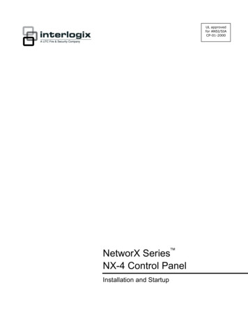
PROGRAMMING THE NX-12 CONTROLNUMERICAL DATA: Numerical data is programmed by entering a number from 0-255 on the numeric keys of thesystem code pad. To view the data in a feature, a binary process is used. With this process, the LED’s for zones 1through 8 are utilized, and the numeric equivalents of their illuminated LED’s are added together to determine thedata in a programming feature. The numeric equivalents of these LED’s are as follows:Zone 1 LED 1Zone 5 LED 16Zone 2 LED 2Zone 6 LED 32Zone 3 LED 4Zone 7 LED 64Zone 4 LED 8Zone 8 LED 128Example: If the numerical data to be programmed in a feature is "66", press [6]-[6] on the code pad. The LED’s forZone 2 and Zone 7 will become illuminated indicating 66 is in that feature (2 64 66). See this example on page10.Once the data is programmed, press the [r] key to enter the data and advance to the next segment of that feature.After the last segment of a feature is programmed, pressing the [r] key will exit that feature, turn the "Ready" LEDoff and the "Armed" LED on. As before, you are now ready to enter another programming feature. If an attempt ismade to program a number too large for a particular segment, the code pad sounder will emit a triple beep,indicating an error, and remain in that segment awaiting a valid entry.OPTION SELECTION DATA: Option selection data will display the current condition (on or off) of eight optionsassociated with the programming feature and segment selected. Pressing a button on the touch-pad (1 thru 8) thatcorresponds to the "option number" within a segment, will toggle (on/off) that option. Pressing any numeric keybetween [1] and [8] for selection of a option, will make the corresponding LED illuminate (option ON). Press thenumber again, and the LED will extinguish (option OFF). You will see that numerous options can be selected fromwithin one segment. For instance, if all eight options of a segment are desired, pressing [1]-[2]-[3]-[4]-[5]-[6]-[7]-[8]will turn on LED's 1 thru 8 as you press the keys, indicating that those options are enabled. After the desired settingof options is selected for this segment, press the [r] key. This will enter the data and automatically advance to thenext segment of the feature. When you are in the last segment of a feature and press the [r] to enter the data, youwill exit that feature. This will now turn the "Ready" LED off and the "Armed" LED on. As before, you are nowready to enter another programming feature.LOADING FACTORY DEFAULTS: There are two ways to load the factory defaults. The first is to enter theprogram mode using the procedure on page 9, then type [9]-[1]-[0]-[#]. The code pad will beep 3 times indicatingthat the loading is in progress. The loading takes about 6 seconds. The second is to type [9][7][1][3][0][0] within 10seconds of power up at any code pad, which is not programmed for master mode. The procedure will default theNX-12 even if it is armed.ENROLLING MODULES AND CODE PADS : For supervision purposes, the NX-12 has the ability to automaticallyfind and store in its memory, the presence of all code pads, zone expanders, wireless receivers, and any othermodule connected to the data terminal whenever exiting the program mode. The enrolling process takes about 12seconds, during which time the "Service" LED will illuminate. Once a module is enrolled, if it is not detected by thecontrol, the "Service" LED will illuminate.10
(Programming Example SAME AS NX16 DAS)11
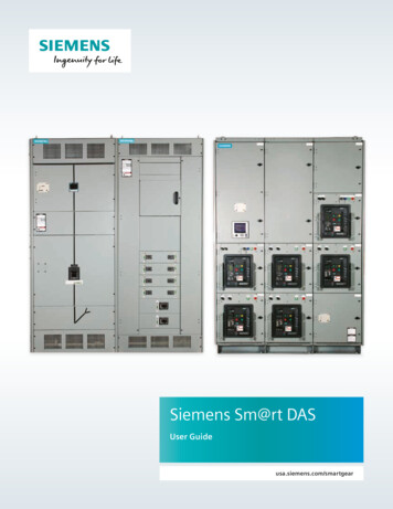
TERMINAL DESCRIPTIONTERMINALEARTHACDESCRIPTIONEarth Ground. Connect to a cold water pipe or a 1 to 3 metre driven rod.AC input. Connect to a 16.5V 25, 40 or 50 VA approved transformer.BELL &BELL -If used as a siren output(default), the speaker rating should be 15 watt at 8 or 16 ohm, or 30/40watt at 4, 8, or 16 ohms. If voltage output is selected in Feature 37, this output becomesvoltage output, 12VDC, 1 Amp maximum load. NOTE: A 3.3KΣΣ resistor may be requiredacross the bell terminals when a 12 VDC siren is used . If no resistor is used, you mayexperience voltage leakage into the siren which will cause these devices to output asmall signal.KP DATAConnect to the data terminal on the code pads and the expanders. Maximum total wire run is800 metres using 14/020 cable. These numbers are for one code pad at the end of the wire.When connecting more than one code pad to the end of the wire, a higher gauge wire or areduction in total wire distance will be required.KP COMConnect to the Common terminal on the code pads and the expanders.KP POSConnect to the Positive terminal on the code pads and the expanders. This terminal and AUXPWR are limited to 1 amp total current when added together.AUX PWR Connect positive wire of all powered devices accept smoke detectors and code pads. Thisterminal and KP POS are limited to 1 amp total current when added together.ZONE 6Connect to one side of zone 8 loop. Connect the other side to com terminal. Open or shortcauses alarm.COMCommon (-) terminal for zones 5 & 6. (See the wiring diagram for examples.)ZONE 5Connect to one side of zone 5 loop. Connect the other side to COM terminal. Open or shortcauses alarm.ZONE 4 ZONE 1Connect as described for zones 5 & 6. (See the wiring diagram for examples.)AUX OUT 4SMOKE (ZONE 7)Aux 4 which also be Zone 7 two wire Smoke detector. Power Current limited to 250 mAwhen output is positive and 250 microamps when output is negative. This output defaultsto Smoke Power, but can be re-configured. Zone 7 may be used for a 2-wire smoke detectorusing a 680 Ohm E.O.L. resistor. W3 must be removed for 2-wire smoke detector loop and Zone7 must be programmed as a Fire Type. For use as Aux Out 4, W2 must be set. The 2-wiresmoke loop cannot be enabled if Zone Doubling is usedAUX OUT 3 AUX OUT 1Connect negative lead of low current device [relay, LED(install 1K resistor in series withLED), etc.]. Connect positive lead of device to AUX PWR . Current limited to 250microamps maximum when output is positive and 250 mA when output is negative.12
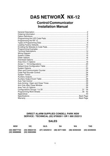
TERMINAL DRAWING13
FEATURE 0CODE REQUIREMENTSFeature 0, segment 1 is used to enable the 6 digit user code option. If 6-digit option is enabled, all arm/disarmcodes, the "Go To Program Code" and duress code are 6 digits. If this option is enabled, the default user 1 codeis [1]-[2]-[3]-[4]-[5]-[6]. The NX-12 has 40 four (4) digit or six (6) digit user codes. Segment 2 is used to enable usercode requirement for functions [r]-[9]-[8] (perform call back download) and [r]-[9]-[9] (answer incoming call fordownload).SEGMENT 1123 –8FEATURE 1SEGMENTS 1-6On enables the 6-digit code option. Its original off state is a 4-digit code.On requires code entry for [rr]-[9]-[8] and [rr]-[9]-[9] functionsRESERVEDGO TO PROGRAM CODE971300Feature 1 contains the "Go To Program Code". This feature contains either a 4 or 6-digit code. If the 6-digit codeoption is enabled in Feature 0, THIS CODE MUST CONTAIN SIX (6) DIGITS. If this option is not enabled inFeature 0, the last 2 segments (digits) will be ignored. With the NX-12 disarmed, the "Go To Program Code" canbe used to enter the Program Mode.FEATURE 2GO TO PROGRAM CODE AREA AND AUTHORISATIONThe "Go To Program Code" can be used as a standard arm/disarm code. When using the code to arm or disarm,the user I.D is 255. (This code may not be changed in the Run Mode.)SEGMENT 1123(4)5678SEGMENT 2(1)(2)FEATURE 3SEGMENTS 1-6Reserved.On enables "Go To Program Code" as an arm only code.On enables "Go To Program Code" as an arm only after closing.On enables "Go To Program Code" as a master code (can change user codes)On enables "Go To Program Code" as an arm/disarm code.On enables "Go To Program Code" to bypass zones.On enables "Go To Program Code" opening and closing reports.ReservedOn enables the "Go To Program Code" for Area #1On enables the "Go To Program Code" for Area #2DURESS CODE151515151515Feature 3 contains the "Duress" code. This feature contains either 4 or 6 digits. If the 6-digit code option isenabled in Feature 0, THIS CODE MUST CONTAIN SIX (6) DIGITS. If the 6-digit option is not enabled in Feature0, the last 2 digits will be ignored. If the duress code is programmed, it will work for all areas.14
FEATURE 4SEGMENTS 1-20PHONE NUMBER ONE (1)1414141414141414141414141414141414141414The first telephone number is programmed in Feature 4. A "14" indicates the end of the phone number. Delays offour seconds can be programmed at any point in the phone number by programming a "13" in the appropriatesegment. If pulse dialing is desired, program a "15" in the segment where pulse dialing should begin. Program an“11" for a “r” and a “12" for a “#”.FEATURE 5SYSTEM ACCOUNT CODESEGMENTS 1-410101010This is the account code sent for any area event (open/close and zone related alarms) that does not have itsaccount code programmed. System events (siren / box tampers, expander troubles etc.) will use the systemaccount unless area one account is programmed.FEATURE 6COMMUNICATOR FORMATSEGMENT 10Feature 6 contains the communicator format used. Select a format from the format selection table. If this featurecontains a "0", the built-in communicator will be disabled, and the NX-12 will function as a local only control.FORMAT SELECTION TABLEDATAFORMATDESCRIPTION0LOCALCOMMUNICATOR IS DISABLED1CONTACT I.DDTMF FORMAT2PAGERREPORTS IN 4 2 DTMF FORMAT. PHONE NUMBERS CAN BEPROGRAMMED VIA CODE PAD IN THE RUN MODE.3DOMESTIC SIRENDOMESTIC DIALLING VIA A SIREN TONE FORMAT. CALL CAN BE KISSEDOFF VIA THE STAR (r) KEY ON A DTMF PHONE. PHONE NUMBERS CANBE PROGRAMMED VIA CODE PAD IN THE RUN MODE.FEATURE 7SEGMENTS 1-20PHONE NUMBER TWO (2)1414141414141414141414141414141414141414The second telephone number is programmed in Feature 7. A "14" indicates the end of the phone number. Delaysof four seconds can be programmed at any point in the phone number by programming a "13" in the appropriatesegment. If pulse dialing is desired, program a "15" in the segment where pulse dialing should begin. Program an“11" for a “r” and a “12" for a “#”.15
FEATURE 8PHONE NUMBER THREE (3)SEGMENTS 1-201414141414141414141414141414141414141414The third telephone number is programmed in Feature 8. A "14" indicates the end of the phone number. Delays offour seconds can be programmed at any point in the phone number by programming a "13" in the appropriatesegment. If pulse dialing is desired, program a "15" in the segment where pulse dialing should begin. Program an“11" for a “r” and a “12" for a “#”.FEATURE 9EVENT REPORT SUMMARYFeature 9 is a summary of event reporting codes found in the Area and System Features. Most Area and Systemreport event are enabled, but will also need to be enabled in this feature. This approach is used to simplify eventselection programming.SEGMENT 1(1)(2)3(4)5(6)7(8)SEGMENT 2(1)(2)(3)4(5)678FEATURE 10SEGMENTS 1-2AlarmsRestoresOpen / CloseBypassZone TroublePower Trouble (AC Failure or Low Battery)TampersTest ReportsSystem Trouble (siren / phone / expander / short circuit)Failure to CommunicateSensor Lost / Sensor Low BatteryProgram, Download, & Full Log (Full Log must also be enabled in system options)Cancel Code (Cancel reporting must also be enabled in area options)Recent Closing / Exit ErrorReservedReservedDIAL ATTEMPTS6RESERVEDFeature 10, Segment 1 is used to enter the number of dial attempts (1 to 15 Attempts) the communicator will maketo Phone #1 before ending the notification process. Factory default is "6" and the communicator will make 6attempts to the first number.FEATURE 11PHONE LINE CUT DELAYSEGMENT 10Feature 11 contains the number of second increments in the Telephone line monitor delay before phone line faultis activated. The Telephone line monitor delay can be programmed in 1 second increments from 1 to 255 seconds.Note. The NX-12 internal phone line monitoring circuit requires approximately 5 seconds to discharge before theNX-12 will sense a missing phone line, you must add this time to the value in this feature when testing this option.A “0” disabled.16
FEATURE 12SEGMENTS 1-8DOWNLOAD ACCESS CODE1600170000
FEATURE 16AREA 1 - O
enabled, area one cannot have full mode Auto Arming selected. (See Feature 22) Automatic Arming - If programmed, the NX-12 will Auto Arm at a specified time. At this time, the code pad will beep for 50 seconds before the panel arms. The auto arming process can be stopped by a valid code entry. The Auto Arming of an area can be programmed to be .