Transcription
Proteus SeriesElectronic Metering PumpInstallation & Operation ManualManual No.: 54038Revision : 01Rev. Date: 08/2016Note: For enhanced control features see manual 54189
ProteusTM Series Model Selection TableERBProteusTM SeriesControl Code1 Manual Control2 Enhance ControlOutput CodeMax. Capacity@ Max Pressure25.6 GPH (21.2 l/h)314.0 GPH (53.0 l/h)418.0 GPH (68.1 l/hr)Voltage Code1110 - 120 VAC 1 Phase US Plug2220 - 240 VAC 1 Phase US Plug3220 - 240 VAC 1 Phase DIN Plug5220 - 240 VAC 1 Phase UK Plug6220 - 240 VAC 1 Phase Australia / New Zealand Plug7220 - 240 VAC 1 Phase Swiss Plug8110 - 120 VAC 1 Phase No PlugLiquid End TypeAStandard Liquid EndVHigh Viscosity Liquid EndSSlurry Liquid EndMax. Pressure1175 psi (12.0 bar) Note: High viscosity option 150 psi (10.3 bar)75 psi (5.0 bar)50 psi (3.5 bar)Head Material1316L Stainless Steel2PVC4Polypropylene7PVDFHead Size Code4Size 4 Diaphragm6Size 6 DiaphragmSeat MaterialATFE/PTPTFEVFKM1316L Stainless Steeli
Ball MaterialCCeramic1316L Stainless Steel4440CTPTFE"O" Ring MaterialNNoneATFE/PVFKMFitting Material1316L Stainless Steel2PVC4Polypropylene7PVDFFitting ConnectionPNPTBBSPSSocketFDN15 FemaleDDN15 MaleTImperial TubeMMetric TubeTubing KitNNone1Kit 12Kit 23Kit 34Kit 4ERB131A44ACA7M2--(1) 175 psi (12 bar) max. with 1/4"x1/2" reinforced PVC hose or 6x12mm reinforced PVC hose; 150 psi (10 bar) max. with 3/8" PE tube or 8mm PE tube.ii
ProteusTM Series Model Selection Table (5.6 GPH)5.6 GPH (21.2 l/h)175 psi (12.0 bar)1 Note: High viscosity option 150 psi (10.3 bar)TMERBProteus SeriesControl and Output Code12Manual Control Unit22Enhanced Control UnitVoltage Code1 110 - 120 VAC 1 Phase US Plug2 220 - 240 VAC 1 Phase US Plug3 220 - 240 VAC 1 Phase DIN Plug5 220 - 240 VAC 1 Phase UK Plug6 220 - 240 VAC 1 Phase Australia / New Zealand Plug7 220 - 240 VAC 1 Phase Swiss Plug8 110 - 120 VAC 1 Phase No PlugLiquid T3ERB121 A44ACA7T1DiaphragmDiaphragmO FPTFE/PVDFFKMTFE/PCeramicTFE/PPVDFTube " NPT/BSPStdPPPVDFPTFE/PVDFFKMTFE/P316LTFE/PPVDFTube " ube MetricStdPPPVDFPTFE/PVDFFKMTFE/P316LTFE/PPVDFTube VCDN15 N15 ube F1/2" Tube PVCDN15 N15 6L316LPTFE/316LFKM316L440CFKM316LNPTNPTHi VisPPPPPTFE/PVDFFKMPTFE316L-PPTube ImperialTypeHeadStdStdConnectionComplete Product Code(1) 175 psi (12 bar) max. with 1/4"x1/2" reinforced PVC hose or 6x12mm reinforced PVC hose; 150 psi (10 bar) max. with 3/8" PE tube or 8mm PE tube.iiiTubing Kit(see table)1122123
ProteusTM Series Model Selection Table (14.0 GPH)14.0 GPH (53.0 l/h)ERBProteusTM Series75 psi (5.0 bar)Control and Output Code13Manual Control Unit23Enhanced Control UnitVoltage Code1 110 - 120 VAC 1 Phase US Plug2 220 - 240 VAC 1 Phase US Plug3 220 - 240 VAC 1 Phase DIN Plug5 220 - 240 VAC 1 Phase UK Plug6 220 - 240 VAC 1 Phase Australia / New Zealand Plug7 220 - 240 VAC 1 Phase Swiss Plug8 110 - 120 VAC 1 Phase No PlugLiquid T3ERB231A44ACA7T1TypeHeadCheck ValveCartridgeDiaphragmDiaphragmO /PCeramicTFE/PPVDFTube 1/2" NPT/BSPStdPPPVDFPTFE/PVDFFKMTFE/P316LTFE/PPVDFTube " ube MetricStdPPPVDFPTFE/PVDFFKMTFE/P316LTFE/PPVDFTube VCDN15 N15 ube F1/2" Tube PVCDN15 N15 6L316LPTFE/316LFKM316L440CFKM316LNPTNPTHi VisPPPPPTFE/PVDFFKMPTFE316L-PPTube ImperialComplete Product CodeivConnectionTubing Kit(see table)1122123
ProteusTM Series Model Selection Table (18.0 GPH)18.0 GPH (68.1 l/hr)50 psi (3.5 bar)TMERBProteus SeriesControl and Output Code14Manual Control Unit24Enhanced Control UnitVoltage Code1110 - 120 VAC 1 Phase US Plug2220 - 240 VAC 1 Phase US Plug3220 - 240 VAC 1 Phase DIN Plug5220 - 240 VAC 1 Phase UK Plug6220 - 240 VAC 1 Phase Australia / New Zealand Plug7220 - 240 VAC 1 Phase Swiss Plug8110 - 120 VAC 1 Phase No PlugLiquid EndCheck PTube -PPTube ImperialStdPPPPPTFEFKM316L-PP/PVCDN15 FemaleStdPPPPPTFEFKMCeramic-PP/PVCDN15 PTFEFKMCeramic-PVDFTube ImperialStdPVDFPVDFPTFEFKMCeramic-PVDF/PVCDN15 16LPTFE316L440CFKM316LNPTHi VisPPPPPTFEPTFE316L-PPNPTHi VisPPPPPTFEPTFE316L-PPTube ImperialComplete Product CodevTubing Kit(see table)44
Tubing & Connection KitsKit #Included Parts1 Injection valve1 Foot valve11 Weight (suction tubing)16' PE tube 3/8”20' Reinforced PVC hose 1/4"x1/2"1 Injection valve1 Foot valve21 Weight (suction tubing)6m PE tube 8mm6m Reinforced PVC hose 6x12mm1 Injection valve32m Reinforced PVC hose 15x23mm (Suction)3m PE tube 1/2" (Discharge)1 Suction hose fitting (1/2” FNPT X 15x23) & 2 Hose clamps42m Reinforced PVC hose 15x23mm (Suction)1 Suction hose fitting (1/2” FNPT X 15x23) & 2 Hose clampsvi
Table of Contents1.0 Precautions . 12.0 Introduction . 42.1 Specifications . 42.2 Unpacking Check List. 53.0 Installation . 63.1 Pump Location and Installation . 63.2 Pump Mounting . 63.2.1 Flooded Suction . 73.3 Tubing Connections . 83.4 Foot Valve / Suction Tubing Installation . 103.5 Injection Check Valve and Discharge Tubing Installation . 114.0 Operation . 124.1 Controls, Inputs and Outputs. 124.2 Display Screen and Keypad . 124.2.1 Pump Start / Stop . 134.2.2 Full Capacity Operation. 134.2.3 Multi-Function Buttons . 134.2.4 Notification Bar . 134.2.5 Display Navigation . 144.2.6 Icons . 144.3 Manual Mode . 164.4 Settings . 164.4.1 Prime Settings . 174.4.2 Firmware Information . 174.4.3 Calibration . 174.4.4 Time / Day . 174.4.5 Keypad Lock Functions . 184.4.6 Set Liquid Measure Units . 194.4.7 LCD Brightness . 204.4.8 Reload Factory Defaults. 204.4.9 Power Loss Options . 214.4.10 Totalizer . 214.4.11 Change Language. 224.4.12 Slow Mode . 234.4.13 Configure Input. 23vii
4.5 Start-Up / Priming. 254.6 Calibration . 275.0 Spare Parts Replacement and Routine Maintenance . 305.15.25.35.4Depressurizing the Discharge Line . 30Diaphragm Replacement. 30Cartridge Valve and O-ring Replacement. 32Injection Check Valve Parts Replacement . 336.0 Troubleshooting . 35viii
Table of FiguresFigure 1: Flooded Suction Pump Mount . 7Figure 2: Ferrule Assembly . 9Figure 3: Foot Valve / Suction Tubing Installation . 10Figure 4: Typical Injection Check Valve Installation . 11Figure 5: Notification Bar . 13Figure 6: Settings . 14Figure 7: Home Screen . 16Figure 8: Settings . 16Figure 9: Firmware Rev. . 17Figure 10: Time/Day . 17Figure 11: Lock Password . 18Figure 12: Password Entry Block . 19Figure 13: Set Unit . 19Figure 14: LCD Brightness . 20Figure 15: Factory Default . 20Figure 16: Factory Default Reset Verification . 21Figure 17: Power Loss Options . 21Figure 18: Totalizer . 22Figure 19: Change Language. 22Figure 20: Slow Mode Settings . 23Figure 21: Configure Input. 24Figure 22: Input Diagram. 25Figure 23: Pin Diagram . 25Figure 24: Prime Settings . 26Figure 25: Pump Calibration (Set Flow Rate) . 27Figure 26: Pump Calibration (Start Flow) . 28Figure 27: Graduated Cylinder . 28Figure 28: Pump Calibration. 29Figure 29: Pump Assembly . 31Figure 30: Diaphragm Replacement (Full Out) . 31Figure 31: Diaphragm Replacement (Full In) . 32Figure 32: Injection Check Valve Assembly . 34ix
PRECAUTIONS1.0 PrecautionsThe following precautions should be taken when working with Milton Roy meteringpumps. Please read this section carefully prior to installation.Protective ClothingALWAYS wear protective clothing, face shield, safety glasses and gloves when working on ornear your metering pump. Additional precautions should be taken depending on the solutionbeing pumped. Refer to Safety Data Sheets (SDS) precautions from your solution supplier.Water Pre-PrimeAll Milton Roy pumps are pre-primed with water when shipped from the factory. If your solution isnot compatible with water, disassemble the Pump Head Assembly. Thoroughly dry the pumphead, valves, O-rings, balls and diaphragm. Reassemble head assembly tightening screws in acrisscross pattern. Refill the pump head with the solution to be pumped before priming thepump. (This will aid in priming.)Liquid CompatibilityCAUTION: The evaluation performed by ETL was tested with water only. The pumps arecertified to NSF 61 with: sodium hypochlorite (12.5%), sulfuric acid (98.5%), sodium hydroxide(50%), and hydrochloric acid (30%). Determine if the materials of construction included in theliquid handling portion of your pump are adequate for the solution (chemical) to be pumped.Always refer to the solution supplier and the Milton Roy Chemical Resistance Chart forcompatibility of your specific Milton Roy metering pump. Contact your local Milton Roy distributorfor further information.Tubing ConnectionsInlet and outlet tubing or pipe sizes must not be reduced. Outlet tubing size must not beincreased. Make certain that all tubing is SECURELY ATTACHED to fittings prior to start-up (seesection 3.3 Tubing Connections). ALWAYS use Milton Roy supplied tubing with your pump, asthe tubing is specifically designed for use with the pump fittings. It is recommended that alltubing be shielded and secure to prevent possible injury in case of rupture or accidentaldamage. If tubing is exposed to sunlight, black UV resistant tubing should be installed. Checktubing frequently for cracks and replace as necessary.Fittings and Machine ThreadsAll fittings should be hand-tightened. An additional 1/8 - 1/4 turn after the fitting is snug may benecessary to provide a leak-proof seal. Excessive overtightening or use of a pipe wrench cancause damage to the fittings, seals, or pump head.Most Milton Roy pumps have straight screw machine threads on the head and fittings and aresealed by the O-rings. DO NOT use PTFE tape or pipe dope to seal these threads. PTFE Tapemay only be used on NPT threads.PlumbingAlways adhere to your local plumbing codes and requirements. Be sure installation does notconstitute a cross connection. Check local plumbing codes for guidelines. Milton Roy is notresponsible for improper installations.1
PRECAUTIONSBack Pressure/Anti-Syphon ValveIf you are pumping downhill or into low or no system pressure, a backpressure /anti-syphondevice should be installed to prevent over pumping or syphoning. Contact your Milton Roydistributor for further information.Electrical ConnectionsWARNING: To reduce the risk of electrical shock, the metering pump must be plugged into aproperly grounded grounding-type receptacle with ratings conforming to the data on the pumpcontrol panel. The pump must be connected to a good ground. Do not use adapters! All wiringmust conform to local electrical codes. If the supply cord is damaged, it must be replaced by themanufacturer, stocking distributor, or authorized repair center in order to avoid a hazard.Fuse and BatteryCAUTION: Battery may explode if mistreated. Do not recharge, disassemble or dispose of in fire.The battery and fuse are internal, factory serviceable parts, and must be replaced by the factoryor a qualified distributor with parts of the same type and rating.FloodingWARNING: Install this pump in a location where flooding cannot occur.Ground Fault Circuit InterrupterWARNING: To reduce the risk of electric shock, install only on a circuit protected by a GroundFault Circuit Interrupter (GFCI).Line DepressurizationTo reduce the risk of chemical splash during disassembly or maintenance, all installationsshould be equipped with line depressurization capability.Over Pressure ProtectionTo ensure safe operation of the pump it is recommended that some type of safety / pressurerelief valve be installed to protect the piping and other system components from failing due toexcessive pressure.Chemical ConcentrationThere is a potential for elevated chemical concentration during periods of no flow, for example,during backwash in the system. Steps, such as turning the pump off, should be taken duringoperation or installation to prevent this.See your distributor about other external control options to help mitigate this risk.Retightening ComponentsPlastic materials will typically exhibit creep characteristics when under pressure over a period oftime and to insure a proper fit it may be necessary to retighten the head bolts periodically. Toinsure proper operation, we recommend tightening the bolts to 25 inch-pounds after the firstweek of operation and on a monthly basis thereafter.2
PRECAUTIONSFlow DisplayThe accuracy of the flow value as shown on the pump display is highly dependent on thespecific application. Calibration is necessary in order to display an accurate measure of the flow.SpillsCAUTION: Spills of Dangerous chemicals should be cleaned up immediately.3
INTRODUCTION2.0 IntroductionMilton Roy's metering pumps deliver the highest level of repetitive accuracy andreliability with the capability to pump a wide range of chemicals. Our comprehensiveselection of pumps means you get the right pump for the right application. Every oneof our pumps is engineered to exceed expectations and is backed by a globalnetwork of highly trained field engineers and aftersales support.Please review this manual carefully. Pay particular attention to warnings andprecautions. Always follow good safety procedures, including the use ofproper clothing, eye and face protection.2.1 SpecificationsTable 1: General SpecificationsIngress protectionIP65 / NEMA 4XVoltage / Frequency100-240 V / 50-60 HzMax. Current / Wattage0.42 A / 42 WOperation environmentIndoor / OutdoorProcess fluid temperature-10 C to 40 COperating ambient temperature-10 C to 40 CStorage temperature-40 C to 70 COperating humidity range:0-95% RH (Non-condensing)Repeatability accuracy /- 1%Turndown1000:1 (200:1 PTFE Seat, 500:1 FKM Seat)Table 2: Liquid End SpecificationsMax. ViscosityOutputCode-Max.[GPH]Flow (1)[l/h]Max. peed[mm][SPM]StandardLiquidEndsHigh ViscosityLiquid tionInletPressureMin. PressureDifferential(Suction 1) Maximum flow rate at maximum pressure. Maximum flow rate may be higher at lower pressures.(2) 175 psi (12 bar) max. with 1/4"x1/2" reinforced PVC hose or 6x12mm reinforced PVC hose;150 psi (10 bar) max. with 3/8" PE tube or 8mm PE tube.(3) High viscosity option 150 psi (10.3 bar).4
UNPACKING CHECK LIST2.2 Unpacking Check ListYour carton will contain many or all of the following items. Please notify the carrierimmediately if there are any signs of damage to the pump or its parts.Metering PumpFoot ValveTubing (0 or 2 Rolls)Ceramic Foot Valve WeightInjection Check ValveExternal Control Cable(6 Pin, 5 Pin, or 4 Pin Cables)Tube Connection Hardware5
INSTALLATION3.0 Installation3.1 Pump Location and InstallationLocate pump in an area convenient to solution tank and electrical supply.The pump should be accessible for routine maintenance, and should not be operatedin ambient temperatures above 104 F (40 C). If the pump will be exposed to directsunlight, Milton Roy black, UV resistant tubing should be installed.3.2 Pump MountingThe pump can be mounted in one of two ways: Flooded Suction (ideal installation); or Suction Lift - when suction lift is less than specified in section 2.1Specifications and the fluid has a specific gravity of water and viscosity ofless than 50 cPs (centipoise). For denser or more viscous solutions, consultdistributor.Note that suction conditions can affect the performance of the pump. This effect ismore pronounced with lower pressure pumps. Consult your distributor for additionalinformation.Your Milton Roy metering pump must be mounted so that the suction and dischargevalves are vertical.NEVER position pump head and fittings horizontally.6
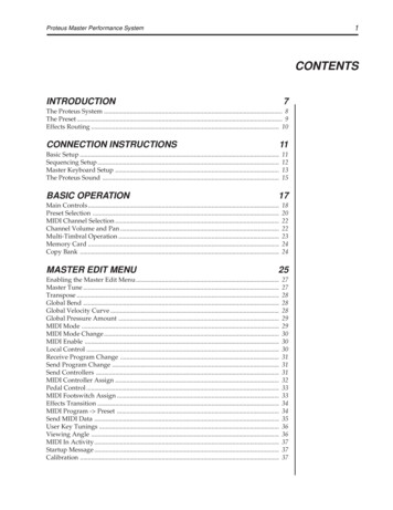
INSTALLATION3.2.1 Flooded SuctionFor flooded suction, the pump is mounted at the base of the storage tank. Thisinstallation is the most trouble-free, and is recommended for very low outputs,solutions that gasify, and high-viscosity solutions. Since the suction tubing is filledwith solution, priming is accomplished quickly and the chance of losing prime isreduced. A foot valve is not necessary in a flooded suction installation.When pumping downhill or into a low or no pressure system, a backpressure / antisyphon device should be installed to prevent over pumping or syphoning.Although popular for all solutions, Milton Roy recommends flooded suctioninstallations for all high-viscosity fluid applications.INCORRECTCORRECTAvoid this type of false flooded suctionFigure 1: Flooded Suction Pump Mount7
INSTALLATION3.3 Tubing ConnectionsUse only Milton Roy supplied tubing with your pump, as the tubing is specificallydesigned for use with the pump fittings. Before installation, all tubing must be cut witha clean square end. Valve and head connections from the factory are capped orplugged to retain pre-prime water. Remove and discard these caps or plugs beforeconnecting tubing.DO NOT USE PLIERS OR PIPE WRENCH ON COUPLING NUTS OR FITTINGS.DO NOT REUSE FERRULES — USE ONLY NEW FERRULES.1. Insert tubing through coupling nut. Tubing should enter the smaller end of thecoupling nut first, orienting the larger opening of the coupling nut toward thetubing end.2. Position a female ferrule about 1 in (25 mm) from end of tubing. For 3/8 inand 8 mm tubing, orient the raised collar of the female ferrule toward thecoupling nut.3. Insert the male ferrule onto the end of the tube, pushing the tube into thebottom of the groove or base.4. Slide the female ferrule down the tubing and with your fingers, press tightlyinto the male ferrule (Figure 2).5. Firmly hand tighten the Coupling Nut onto the fitting.NOTE: Tightening with pliers may cause the ferrules to break.Replacement ferrules and coupling nutsare available as the following kit numbers:54714 - 3/8" TUBE54715 - 1/4"x1/2" HOSE54716 - 8mm TUBE54717 - 6x12mm HOSE54718 - 1/2" TUBEOne kit is needed for each end of the tube.8
INSTALLATIONFigure 2: Ferrule Assembly9
INSTALLATION3.4 Foot Valve / Suction Tubing InstallationThe foot valve acts as a check valve to keep the pump primed in suction liftapplications.The foot valve is designed to be submersed in the solution tank or drum andmust sit in a vertical position at the bottom. Position approximately 2 in (50 mm)above the bottom of the tank or drum sediment layer.The ceramic weight, when installed, helps position the foot valve in a verticalposition.1. Attach the foot valve to one end of the suction tubing (see section 3.3 TubingConnections).2. Slide the ceramic weight over the tubing end until it contacts the top of the footvalve coupling nut.3. Place foot valve and tubing into the solution tank. Check that the foot valve isvertical and approximately 2 in (50 mm) from the bottom of the tank or drum(Figure 3). Connect the other end of the tubing to the suction side of the pumphead (bottom side) (see section 3.3 Tubing Connections).Note: Pump models equipped with high-viscosity liquid ends are not equipped with footvalves. Flooded suction is recommended. A 1/2 in NPT connector is included for floodedsuction installations.Use CeramicWeight2 in (50 mm) forSediment AccumulationINCORRECTCORRECTFoot Valve tilted sideways WILL NOT PRIMEFoot Valve must remain verticalFigure 3: Foot Valve / Suction Tubing Installation10
INSTALLATION3.5 Injection Check Valve and Discharge Tubing InstallationThe injection check valve prevents backflow from a treated line.1. Install the injection check valve at the location where chemical is being injectedinto the system. Any size female NPT fitting or pipe tee with a reducing bushingto ½ in female NPT will accept the injection check valve. PTFE tape should onlybe used on threads that are connected with pipes.2. When installing the injection check valve, be sure to position it so that the valveenters the bottom of your pipe in a vertical position. Variations left and right within80 are acceptable (Figure 4).3. After cutting an appropriate length of tubing, connect tubing to the injection checkvalve then back to the discharge side of the pump head. Make sure it does notcrimp or come into contact with hot or sharp surfaces (see section 3.3 TubingConnections).Figure 4: Typical Injection Check Valve Installation11
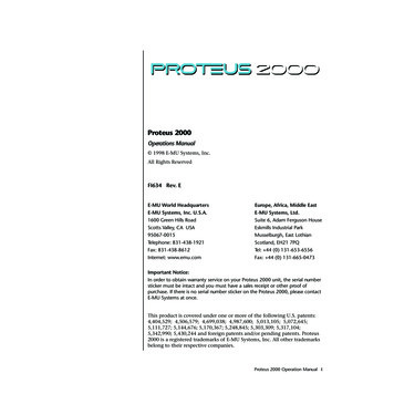
OPERATION4.0 OperationThis manual covers features supported in the manual control model Proteus Seriespumps.4.1 Controls, Inputs and Outputs1. Start / Stop Button: Starts or stops the pump. Itaffects only the pumping function. The pump isalways powered when it is plugged in.2. Full Capacity Button: Sends the pump output to100% regardless of current settings.3. Pump Status Indicator: Glows green constantlywhen pump is operating, including between strokes.4. Low Level Indicator: Glows amber when tanksensor detects a low fluid level.5. LCD Display: Shows current pump status, operatingmode, settings, alarms, etc.6. Up / Down Multi-Function Buttons: Function varieswith the active display screen. Used forincrementing, decrementing and navigation.7. Multi-Function Buttons: Function varies with theactive display screen and is indicated by on-screenicons above the buttons. Used to highlight, selectand navigate.8. Input / Output Connector: This connector is used forthe special functions associated with the Manualcontrols (e.g., Digital Input).4.2 Display Screen and KeypadAll control input and monitoring of pump status is done using the display screen andkeypad. All inputs entered while the pump is running affect pump output immediately. Ifchanges are made while the pump is at idle, the new settings will be in effect when thepump is started.12
OPERATION4.2.1 Pump Start / StopThe Start / Stop button toggles the pump ON and OFF, independent of other settings.When running it will operate based on the settings and external signals currently ineffect. There is no need to stop the pump to change settings. When the pump is on, thepump status indicator will glow green.4.2.2 Full Capacity OperationIf the 100% button is pressed, the current settings and external signals will betemporarily overridden. Pump output will go immediately to full capacity and remainthere. If the pump is not running when the 100% button is pressed, it will start and run atfull capacity. To
Proteus Series Electronic Metering Pump Installation & Operation Manual Manual No.: 54038 Revision : 01 Rev. Date: 08/2016 Note: For enhanced control features see manual 54189 . i ProteusTM Series Model Selection Table ERB TMProteus Series Control Code 1 Manual Control 2 Enhance Control .