Transcription
Processing and Application of Ceramics 12 [2] (2018) 189–197https://doi.org/10.2298/PAC1802189SSevere sink-in occurrence in thermally sprayed hydroxyapatite coatingSaeed Saber-Samandari1, , Saeid Baradaran1 , Bahman Nasiri-Tabrizi1 , Kadhim Alamara2,Wan Jeffrey Basirun31 NewTechnologies Research Center, Amirkabir University of Technology, Tehran, Iranand Renewable Energy Engineering (SREE), University of Sharjah, United Arab Emirates3 Department of Chemistry, Faculty of Science, University of Malaya, 50603 Kuala Lumpur, Malaysia2 SustainableReceived 6 March 2018; Received in revised form 11 June 2018; Accepted 22 June 2018AbstractThe performance of orthopaedic and dental implants counts on the ability to appraise the mechanical properties of biomaterials. In the present study, nanoindentation was used to characterize the mechanical propertiesof thermally sprayed hydroxyapatite-coated commercial pure titanium (HA/CP-Ti). From the XRD patterns, theas-sprayed HA coating showed an inhomogeneous mixture of polycrystalline and amorphous phases along withthe formation of the decomposed constituents including tricalcium phosphate (α-TCP), tetracalcium phosphate(TTCP) and calcium oxide (CaO). The SEM micrographs of HA coating indicated some incompletely meltedparticles on the surface of flattened droplets, where the average pore size was around 0.8 µm. After the loadunload indentation experiment, a clear severe sink-in deformation feature was observed around the residualindentation impression of the amorphous part. In contrast, pile-up only occurs during loading for the crystalline part of the coating. In addition, the crystalline part of the coating exhibited a Young’s modulus andhardness of around 120.46 and 7.91 GPa, respectively, which were almost 8 and 259% higher than that of thebare CP-Ti substrate. This is the first report on the nanoindentation characterization of the inhomogeneousmixture of various phase structures in thermally sprayed HA coatings.Keywords: thermal spraying, hydroxyapatite coating, nanoindentation, mechanical behaviour, severe sink-inI. IntroductionAmong various metallic biomaterials, titanium (Ti)and Ti-based alloys are widely employed for dental andorthopaedic implants due to their excellent corrosion resistance and mechanical properties. However, this typeof biomaterial cannot meet all of the clinical requirements and thus surface-modification techniques may beused to decrease wear and corrosion, which may occurat the implant level [1,2]. To improve the bone-implantcoupling and the therapeutic process, the incorporationof calcium phosphate coatings is constantly being reviewed [3–6]. Among them, hydroxyapatite (HA) coatings are utilized in clinical applications, especially forcoating of metallic implants because of their chemical similarity to the mineral constituent of natural boneas well as excellent biocompatibility, bioactivity andCorresponding author: tel: 98 21 6454 5193,fax: 98 21 6640 2044,e-mail: saeedss@aut.ac.ir (S. Saber-Samandari)e-mail: saeid baradaran@aut.ac.ir (S. Baradaran) 189biodegradability [7–11]. For successful performance ofthe main functions, bioceramic coatings should meetnumerous obligations. Therefore, careful considerationshould be given to the mechanical properties and longterm stability of the HA coatings [12].Given that almost all kinds of materials can be developed on different substrates, many possibilities areaccessible to categorize the accessible kinds of coatings. For instance, they might be sorted in accordancewith the development method, where all kinds of coatings can be grouped into two big classes including conversion ones, which are generated by reaction products of the base material and deposited ones [13]. Further, the deposited approach might be categorized in accordance with the deposition methods, such as plasmaspraying, high-velocity oxy-fuel spraying, RF magnetron sputtering, pulsed laser deposition (laser ablation), dip coating, ion beam assisted deposition, electrostatic spray deposition, spin coating, sol-gel technique,electrophoretic deposition, electrochemical (cathodic)deposition, biomimetic process, hydrothermal deposi-
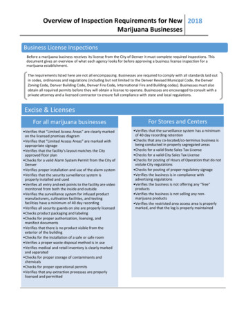
S. Saber-Samandari et al. / Processing and Application of Ceramics 12 [2] (2018) 189–197tion, thermal substrate deposition, hot isostatic pressing, micro-arc oxidation, and dynamic mixing method[14–18]. Among them, thermally sprayed HA coatingsare widely used for various biomedical applications because of its ability to form thin HA coatings on avariety of orthopaedic prosthesis and dental implants[19–23]. Based on the literature, by choosing the optimum relation between particle sizes, type and pressure of gas, plasma rate and cooling cycle of the substrates, various coatings with tailored properties canbe obtained. However, in view of the fact that thermal spraying takes place at very high temperatures, theformed hot droplets continuously heat up the undercoats, which might give rise to phase transition and recrystallization of the areas close to the surface. Indeed,such microstructural changes make further vagueness ofthe adhesive behaviour and mechanical properties of thecoatings [13,24]. Accordingly, there is a necessity to assess the mechanical behaviour of the thermally sprayedHA-coated implant. In this regard, nanoindentation ismore perceptive than that of the conventional analysis that just provides a quantitative assessment of thebonding within the coating. If necessary, nanoindentation could also be utilized in association with mechanical property distributions determined from indentationon the cross-section [23,25]. Therefore, the aim of thepresent work is to quantitatively assess the mechanicalproperties of HA/CP-Ti by nanoindentation test, wheresome unusual phenomena were also found around theresidual indentation impression.The impact of thermal spray parameters, such as preheating temperature, spray distance, feedstock morphology and particles size, angle of spraying, and particlevelocity on mechanical properties of HA-coated implantare available in literature [26–28]. The coatings in thepresent work possess amorphous phases along with decomposed constituent [29]. Up to now, no research hascomprehensively documented the effectiveness of theinhomogeneous mixture of various compounds on thenanoindentation properties of the thermally sprayed HAcoatings. Thus, this work more specifically addressesthe effect of phase constituents (i.e. polycrystalline andamorphous phases) on mechanical properties includinghardness and elastic modulus of HA coating.The sieved powder was passed through into a powderfeeder (Metco 3MP, Sulzer Metco, Wohlen, Switzerland) and then into a flame spray torch (Metco 5P, SulzerMetco, Wohlen, Switzerland) operated with acetyleneand oxygen, with air as the carrier gas at a flow rate of50 g/min. The acetylene and oxygen pressures were 103and 200 kPa, respectively. The polished CP-Ti substratewas placed 15 cm from the torch and the HA powderwas sprayed onto the 300 C preheated substrate surface. Half of the treated specimen was mounted in epoxyresin (Aka-Resin & Aka-Cure, Denmark) to make support throughout the cross-sectional cutting and metallographic preparation to obtain smooth sample surfacesfor the nanoindentation experiments. Fine grinding wasperformed with SiC abrasive papers of decreasing gritsize (800, 1200 and 2400 grit) and polishing includeda 3 micron diamond suspension on a Largo surface followed by a 0.05 µm colloidal silica on an OPS cloth.Hereon, the spraying parameters were regulated to attain maximum coating constancy and homogeneity onthe basis of literature and previous pilot studies [30–32].Figure 1 shows a schematic illustration of the thermalspraying process used in the present research.2.2. Coating characterizationThe phase compositions of feedstock powder and HAcoating were determined using an X-ray diffractometer(Philips PW1800) with Cu-Kα radiation at 40 kV and30 mA over a 2θ range between 10 and 80 with thestep size of 0.02 and a fine slit. The surface morphology of the as-sprayed coatings was examined with ascanning electron microscopy (XL30 Philips). Energy-II. Materials and methods2.1. Preparation of HA coatingThe CP-Ti substrate was prepared by grinding SiCabrasive paper of 320 grit size at a speed of 300 rpmfor 1 min. After that, fine grinding was performed onan MD-Largo surface for 4 min with DiaPro Allegro(Struers) as the lubricant for faster, more cost-efficientand much easier materialographic sample preparation.The final polishing was then conducted using 0.04 µmcolloidal silica on a MD-Chem cloth for 5 min. Priorto thermal spray coating, HA powder (CAM implants,Netherlands) was sieved to a particle size of 20–40 µm.Figure 1. Schematic illustration of the thermal sprayingprocess used in the present research190
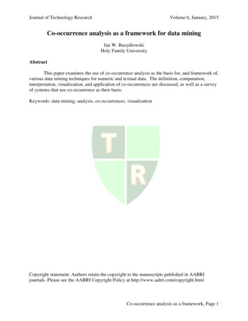
S. Saber-Samandari et al. / Processing and Application of Ceramics 12 [2] (2018) 189–197dispersive X-ray spectrometry (EDS) outfitted with theSEM was used to determine the chemical compositionof the specimens. The surface roughness parameters,Ra (arithmetic average) and Rt (maximum height ofthe profile) were measured using an XP-2 High Resolution Surface Profilometer, Ambios Technology, Inc.,CA, USA. Mechanical properties of the HA coatingswere determined by a nano-based indentation system(Ultra Micro-Indentation System, UMIS-2000, CSIRO,Australia) with a calibrated Berkovich indenter (threesided pyramidal) (Synton, Switzerland). Herein, a seriesof indentations were made on the cross-sectional surfaces of the samples using a peak load of 50 mN, whereUMIS software based on the Oliver-Pharr method wasemployed to determine Young’s modulus (E) and hardness (H). It is necessary to mention that all nanoindentation experiments commenced after a thermal soak ofthe instrument, minimum for 1 h, so the thermal driftwas deemed to be almost negligible ( 0.05 nm s-1 ) before each test.III. Results and discussion3.1. Phase analysisFigure 2 shows the XRD patterns of a reference amorphous calcium phosphate (ACP) coating, the feedstockHA powder and thermally sprayed HA coating. FromFig. 2a, a broad peak assigned to an amorphous phase isobserved in the XRD profile of the stress-relieved ACP[33]. On the other hand, the crystalline structure in thefeedstock HA powder demonstrates well-defined peaksin the X-ray diffraction pattern, where the typical latticefringes with d parameters of 0.344, 0.281, 0.277, 0.272,0.263, 0.226, 0.194, 0.184, and 0.172 nm are ascribedto (002), (211), (112), (300), (202), (310), (222), (213),and (004) planes of HA (JCPDS #09-0432), respectively(Fig. 2b).As shown in Fig. 2c, the diffraction profile of the assprayed HA coating demonstrates broad peaks at 31.7 ,49.4 , and 53.1 . This suggests that the as-deposited HAcoating possesses an inhomogeneous mixture of polycrystalline and amorphous phases along with the formation of the decomposed constituents including twomain diffraction peaks corresponding to (200) and (040)planes of TTCP (#025-1137) with monoclinic structure, the (170) crystal plane of α-TCP (#09-0348) withorthorhombic structure and a minor peak attributed to(200) plane of CaO (#037-1497). The lattice constants(a- and c-axis) and unit cell volume (V) of the assprayed HA coating are illustrated in Fig. 2d,e,f. Basedon the obtained data, the lattice parameters of the standard HA (JCPDS #09-0432) along the a- and c-axis are9.418 and 6.884 Å, respectively, whereas these valuesdecreased to 9.404 and 6.881 Å for the as-sprayed HAcoating (Fig. 2d,e). Accordingly, the unit cell volumedecreased from 528.8 Å3 for the standard to 527.0 Å3for the as-sprayed HA coating, which is consistent withXRD peaks shifting toward higher angles (Fig. 2f). Inthis case, a dramatic decrease in the cell volume couldbe attributed to the substitution of PO43 – with CO32 –groups in the HA lattice owing to the smaller ionic radius of the carbonate (1.78 Å) than of the phosphate(2.38 Å) [34]. To appraise the lattice mismatch, the inplane (εa ) and out-of-plane (εc ) strains were measuredFigure 2. XRD patterns of: a) a reference ACP coating, b) the feedstock HA powder [33] and c) thermally sprayed HA coating,as well as the a- and c-lattice constants (d,e) and unit cell volume, V (f) of the HA coating191
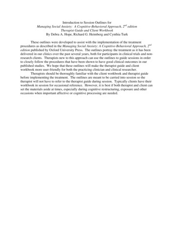
S. Saber-Samandari et al. / Processing and Application of Ceramics 12 [2] (2018) 189–197Figure 3. Typical top- (a) and cross-sectional (b) SEM micrographs, as well as the EDS line scan analysis (c) of the as-sprayedHA coating on CP-Ti substratethan HA (16.0 10 6 K-1 ), which would impact on thecrack formation within the splat during the final stepof solidification. On the other hand, among the decomposed components, the presence of high amounts ofCaO in the coating makes adverse effects because hydration reactions happening throughout storage or after implantation transform calcium oxide into calciumhydroxide with 50% volume increasing, causing significant internal strains and cracks [13]. Moreover, thesmall micro-pores are generated due to the isolatedpores within the feedstock HA powder. These small gasbubbles would coalesce to form a large bubble withinthe droplet in accordance with the dynamics of gas bubble within liquid [37].The cross-sectional SEM micrograph of the HA coating in Fig. 3b shows good bonding between the ceramic coating and metallic substrate. From this figure,the as-sprayed HA coating exhibits an average thickness of 70 4 µm, measured at 5 positions on a polished cross-section and then averaged. Due to the inherent brittleness of the HA material, the microcracks wereformed during the polishing procedure. From the crosssectional SEM image in Fig. 3b, the spreading of amorphous phases and by-products is inhomogeneous. Thisstructure contains three domains with different contrast,including i) light grey, ii) grey and iii) dark, which represent polycrystalline phase, amorphous phase (I) andamorphous phase (II), respectively. The formation ofthese various admixtures and metastable phases is dueto the very high processing temperature, which resultsin incongruent melting together with an incomplete dehydroxylation of HA, and a negligible decompositionof other phases, followed by a fast solidification [13].This is consistent with the XRD profiles, indicating thatan inhomogeneous mixture of polycrystalline and amorphous phases is formed during thermal spraying of HAon the preheated CP-Ti substrate. The existence of suchinhomogeneous structure can provide different properties than the initial bulk materials [38]. It is reportedthat the impact of the metastable and amorphous phasespresence on the coating features depends on their posi-by contrasting the lattice parameters of the HA coatingwith the lattice parameters of unstrained HA [35]:a a0a0c c0εc c0εa (1)(2)The in-plane and out-of-plane strains of the assprayed HA coating are 0.001 and 0.0004, respectively, where the negative values of the strains point outthe compressive strain in the coating. This result showsthat there is just minor lattice disparity as the PO43 –groups are replaced by the CO32 – .3.2. Surface properties and EDS analysisFigure 3 shows the typical top- and cross-sectionalSEM micrographs as well as the EDS line scan analysisof the as-sprayed HA coating on CP-Ti substrate. SEMimage (Fig. 3a) confirms that the as-sprayed HA coatingexhibit some partly melted particles on the surface offlattened droplets.Similar observations were also reported in previousstudy [13]. It is found that dimensions of the feedstockHA powder can affect the melting characteristics withinthe thermal spraying process, where coarser particlesundergo a lesser degree of melting compared to smallerparticles. For instance, HA particles with sizes above 55 µm were observed to stay crystalline and demonstrated slight or no melting throughout thermal spraying. On the other hand, while HA particles with sizesranging between 30–55 µm were partly melted and comprised of combinations of amorphous and crystallinephases. In addition, HA particles less than 30 µm werecompletely melted and consisted of a large fraction ofACP and small amount of CaO [36].From Fig. 3a, some micro-cracks and open pores withthe average size of around 0.8 µm are developed on thesurface of the splats. Here, a residual tensile stress isunavoidable within the splats owing to the lower coefficient of thermal expansion of the CP-Ti (8.6 10 6 K-1 )192
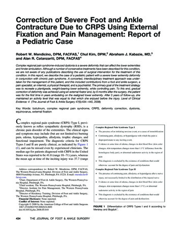
S. Saber-Samandari et al. / Processing and Application of Ceramics 12 [2] (2018) 189–197Figure 4. Surface roughness profiles for the as-sprayed HA coatings on the untreated (a) and preheated CP-Ti substrate (b) aswell as surface roughness parameters, Ra and R t (c)tion. For instance, being positioned in the surface layer,such phases endorse growth of bone tissues because ofa higher bioresorption, whereas close to the interface ofcoating-substrate, a rapid dissolution of these phases results in the adhesive strength falling and peeling off thedeposits prior to the bone tissue generation [13].From the EDS line scan analysis in Fig. 3c, the oxygen content is uniform throughout the thickness direction from the coating surface to the Ti–HA interface,which is consistent with the desired HA composition.On the contrary, Ca and P contents slowly reduce at7 µm from the interface. This suggests that the presenceof O is vital to the development of the HA coating. Itis important to stress that the presence of Ti in the deposit verifies its diffusion within the coating owing tothe preheating of the CP-Ti substrate before the coatingprocess.In general, the roughness of coating might be appliedas a measure of the particles melting degree. For example, as the deposited particles reach a more fluid stateduring the plasma flame they turn into less viscous. Accordingly, they can be expanded to a greater degree overthe undercoat, where a smoother layer is formed. On theother hand, partly melted particles cannot squash simplyon the surface, leading to large fluctuations and roughcoatings [39]. Figure 4 displays the surface roughnessprofiles for the as-sprayed HA coatings on the untreatedand preheated CP-Ti substrate as well as surface roughness parameters (Ra and Rt ).As can be seen in Fig. 4, the HA coating on preheatedsubstrate possesses lower roughness compared to theuntreated sample. This behaviour can be caused by theenhanced spreading of melted particles over the surface[13]. The results of surface roughness measurements forthe HA coatings showed that the Ra and Rt values for theuntreated sample are 22.5 1.1 and 70.0 3.3 µm, respectively (Fig. 4c). These values reached 5.0 0.2 and42.0 2.1 µm in the case of preheated CP-Ti substrate,which is consistent with the previous findings that deposits with surface roughness values of Ra 7, 10 and24 µm were produced by thermal spraying [39].3.3. Nanoindentation assessmentFigure 5 shows schematic views of the deformed surfaces after tip removal, load-displacement curves andresidual impressions of indentation for elastic, plastic and elastic-plastic indentations. The sense of loading and unloading is shown by the arrows. In the caseFigure 5. Schematic views of the deformed surfaces after tipremoval, load-displacement curves and residual impressionsof indentation for: a) elastic, b) plastic and c) elastic-plasticindentations193
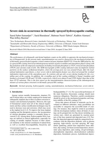
S. Saber-Samandari et al. / Processing and Application of Ceramics 12 [2] (2018) 189–197crystalline part of the coating can be caused by beingin the vicinity of the amorphous phase and the presence of cracks [12]. From Figs. 6c and 6d, near thecontact zone, one can see that the amorphous phase (I)region of the HA coating is downwards against the tipof indenter which makes a sink-in on the rims. In theamorphous phase (II) region, severe sink-in is observedwhich confirms that this region of the HA coating hashigher strain-hardening ability than the other parts as thesurface surrounding the indenter has a great tendency tosink-in (Figs. 6e and 6f). A similar behaviour was observed by Mullins et al. [42] for cortical bone duringnanoindentation, but they have not described this phenomenon.In general, pile-up and sink-in are the most importantphenomena during nanoindentation tests, which showthe deformation of specimen around the contact point.These phenomena are connected to the nanoindentationof elastic-plastic materials. In the pile-up phenomenon,contact depth is always deeper than the total depth of indentation, accordingly the projected area is always underestimated. This underestimated area could overestimate both hardness and reduced elastic modulus, witha more noteworthy impact on hardness [32]. In contrast, the sink-in leads to contact area that is smallerthan the cross-sectional area. As these phenomena candrastically affect the contact area and can cause imprecise calculations of the indented material, these deformations have large impacts on the measurements of indentation moduli. From the literature, highest pile-upis commonly diagnosed on the supposition of elasticplastic materials, whereas highest sink-in takes place forstrain-hardening materials. It is found that different materials can be deformed in different modes in the nearness of the contact point [43]. Consequently, it can bededuced that the observed deformations in different regions of the HA coating are related only to intrinsic material properties and cannot be derived from the appliedload. Figure 7 shows the load-displacement curves forindentations into polycrystalline, amorphous (I) and (II)Figure 6. SEM micrographs of nanoindentations createdwith a Berkovich indenter in a cross-section of HA/CP-Ti;polycrystalline phase (a,b), amorphous phase (I) (c,d) andamorphous phase (II) (e,f)of fully elastic contact, the proportion of the loadeddisplacement recoverable during unloading is 100%.Therefore, no impression of the indentation is observedafter unloading as shown in Fig. 5a. In contrast, theproportion of the loaded displacement recoverable during unloading for fully plastic contact response is 0%,where the maximum total surface deflection (δL ) isrecorded for a given applied load P (Fig. 5b). In thiscase, no deformation takes place until yield stress is attained as plastic flow occurs. Besides, no recovery during unloading is detected and the impression remainsunchanged. Typical load-displacement curve for elasticplastic behaviour is also presented in Fig. 5c, where δRis the recorded displacement following elastic recoveryof the surface flexure, which presents a measurement ofthe plastic component of the surface response [40,41].Nanoindentation has the ability to be used as a probing tool to characterize the alteration in mechanical behaviour through the coating thickness. The SEM micrographs of nanoindentations created with a same indenter(Berkovich indenter) in a cross-section of HA/CP-Ti areshown in Fig. 6.The SEM images in Figs. 6a and 6b reveal the presence of microcracks and deformations around the indent. In addition, the HA coating shows little or no pileup at the edges of the indent in the crystalline part ofthe coating. A deep penetration of the indenter in theFigure 7. The load-displacement curves for indentations intopolycrystalline, amorphous (I) and (II) regions of the HAcoating compared to single crystal HA194
S. Saber-Samandari et al. / Processing and Application of Ceramics 12 [2] (2018) 189–197Figure 8. Maximum depth (a), hardness (b) and Young’s modulus (c) values of the polycrystalline, amorphous (I) and (II)regions of the HA coating contrasted to the single crystal HAregions of the HA coating compared to single crystalHA. In addition, maximum depth, hardness and Young’smodulus values of the polycrystalline, amorphous (I)and (II) regions of the HA coating contrasted to the single crystal HA are shown in Fig. 8. It is obvious thatthe amorphous phases are effortlessly deformed as exposed in the horizontal displacement at the peak load.This shows that more creep occurs in the amorphous (I)and (II) regions compared to the crystalline phase [12].As can be seen, the polycrystalline region of theHA coating is more resistant to indent and possesseshigher hardness (7.91 GPa) and lower penetration depth(585 nm) than that of the single crystal HA (Figs. 8a and8b). A dramatic decrease in the hardness value to 1.92and 1.38 GPa is observed for the regions of the amorphous phases (I) and (II), respectively. The same trend isalso seen in Young’s modulus as shown in Fig. 8c, wherethe E values decreased from 120.46 GPa in the polycrystalline region to 54.28 and 43.02 GPa for the amorphous phases (I) and (II), respectively. This feature canbe linked to the random distribution of defects withinthe thermally sprayed coatings as one of the key factorsresponsible for the anisotropy in mechanical propertiesof the coating [37].tion of the decomposed constituents. From the structuralassessment, the unit cell volume declined to 527.0 Å3for the as-sprayed HA coating. Besides, the in-planeand out-of-plane strains of the as-sprayed HA coatingexhibited a minor lattice disparity compared to standard HA. From the SEM observations, the as-sprayedHA coating had a mean thickness of 70 4 µm, wherethe distribution of by-products and amorphous phaseswas inhomogeneous. The observed deformations in different regions of the HA coating were related only tointrinsic material properties, where severe sink-in wasdetected in the amorphous phase (II) region. Based onthe nanoindentation behaviour, the polycrystalline region of the HA coating was more resistant to indentand showed the highest hardness of 7.91 GPa and lowestpenetration depth of 585 nm. In addition, a significantdecrease in the hardness value was observed for the regions of the amorphous phases. A same trend was alsonoticed in Young’s modulus. It can be concluded that therandom distribution of defects within inhomogeneousphase states had significant effects on the anisotropyin mechanical behaviour of the thermally sprayed HAcoatings.Acknowledgement: The authors would like to acknowledge the Amirkabir University of Technologyfor providing necessary resources and facilities for thepresent study.IV. ConclusionsA new approach on the nanoindentation characterization of the inhomogeneous mixture of various phasestructures in thermally sprayed HA coatings was developed. The XRD results showed that the as-deposited HAcoating contained an inhomogeneous mixture of polycrystalline and amorphous phases along with the forma-References1. M. Sarraf, B.A. Razak, R. Crum, C. Gámez, B. Ramirez,N.H.B. Abu Kasim, B. Nasiri-Tabrizi, V. Gupta, N.L.195
S. Saber-Samandari et al. / Processing and Application of Ceramics 12 [2] (2018) man, W.J. Basirun, “Adhesion measurement ofhighly-ordered TiO2 nanotubes on Ti-6Al-4V alloy”, Process. Appl. Ceram., 11 [4] (2017) 311–321.A. Rafieerad, A. Bushroa, B. Nasiri-Tabrizi, A. Fallahpour, J. Vadivelu, S. Musa, S. Kaboli, “GEP-based methodto formulate adhesion strength and hardness of Nb PVDcoated on Tie6Ale7Nb aimed at developing mixed oxidenanotubular arrays”, J. Mech. Behav. Biomed. Mater., 61[9] (2016) 182–196.T. Mokabber, L.Q. Lu, P. van Rijn, A.I. Vakis, Y.T. Pei,“Crystal growth mechanism of calcium phosphate coatingson titanium by electrochemical deposition”, Surf. Coat.Technol., 334 [2] (2018) 526–535.S. Bose, D. Banerjee, A. Shivaram, S. Tarafder, A. Bandyopadhyay, “Calcium phosphate coated 3D printed poroustitanium with nanoscale surface modification for orthopedic and dental applications”, Mater. Des., 151 [15] (2018)102–112.A.M. Vilardell, N. Cinca, I.G. Cano, A. Concustell, S.Dosta, J.M. Guilemany, S. Estradé, A. Ruiz-Caridad, F.Peiró, “Dense nanostructured calcium phosphate coatingon titanium by cold spray”, J. Eur. Ceram. Soc., 37 [4](2017) 1747–1755.G. Graziani, M. Bianchi, E. Sassoni, A. Russo, M. Marcacci, “Ion-substituted calcium phosphate coatings deposited by plasma-assisted techniques: A review”, Mater.Sci. Eng. C, 74 [6] (2017) 219–229.K. Dudek, M. Dulski, T. Goryczka, A. Gerle, “Structuralchanges of hydroxyapatite coating electrophoretically deposited on NiTi shape memory alloy”, Ceram. Int., 44 [10](2018) 11292–11300.B. Zheng, Y. Luo, H. Liao, C. Zhang, “Investigation of thecrystallinity of suspension plasma sprayed hydroxyapatitecoatings”, J. Eur. Ceram. Soc., 37 [15] (2017) 5017–5021.S. Bose, A.A. Vu, K. Emshadi, A. Bandyopadhyay, “Effects of polycaprolactone on alendronate drug release fromMg-doped hydroxyapatite coating on titanium”, Mater.Sci. Eng. C, 88 [7] (2018) 166–171.A. Karthika, “Aliovalent ions substituted hydroxyapatitecoating on titanium for improved medical applications”,Mater. Today, 5 [2] (2018) 8768–8774.C. Hu, L. Yu, M. Wei, “Sectioning studies of biomimeticcollagen-hydroxyapatite coatings on Ti-6Al-4V substratesusing focused ion beam”, Appl. Surf. Sci., 444 [20] (2018)590–597.K.A. Gross, S. Saber-Samandari, K.S. Heemann, “Evaluation of commercial implants with nanoindentation definesfuture development needs for hydroxyapatite coatings”, J.Biomed. Mater. Res., 93B [1] (2010) 1–8.S.V. Dorozhkin, “Calcium orthophosphate deposits:Preparation, properties and biomedical applications”,Mater. Sci. Eng. C, 55 [10] (2015) 272–326.Y. Yang, K.H. Kim, J.L. Ong, “A review on calcium phosphate coatings produced using a sputtering process - an alternative to plasma spraying”, Biomaterials, 26 [3] (2005)327–337.R. Narayanan, S.K. Seshadri, T.Y. Kwon, K.H. Kim, “Calcium phosphate-based coatings on titanium and its alloys”,J. Biomed. Mater. Res., 85B [1] (2008) 279–299.A.R. Rafieerad, A.R. Bushroa, B. Nasiri-Tabrizi, S.Baradaran, S. Shahtalebi, S. Khanahmadi, M. AfsharMohajer, J. Vadivelu, F. Yusof, W.J. Basirun, “In-vitrobioassay of electrophoretically deposited .29.30.31.32.33.196zirconia nanocomposite coating on Ti-6Al-7Nb implant”,Adv. Appl. Ceram., 116 [6] (
at the implant level [1,2]. To improve the bone-implant coupling and the therapeutic process, the incorporation of calcium phosphate coatings is constantly being re-viewed [3-6]. Among them, hydroxyapatite(HA) coat-ings are utilized in clinical applications, especially for coating of metallic implants because of their chemi-