Transcription
Gears – and HowTheir World isChangingbyNeville W. Sachs, P.E.Neville W. Sachs, P.E., PLLC1Neville W. Sachs, P.E. (c) 2014
The Plan Discuss the more important terms Explain some types of gears and theiroperation Describe some basic gear metallurgy andwhat’s changing in gear design Show how they fail Ask some questions to see if you’re learninganything.My thanks to The Falk Corporation (now a division ofRexnord) for some of the pictures and lots of education.2Neville W. Sachs, P.E. (c) 2014
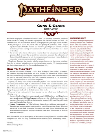
Gear Tooth TerminologyCircular PitchActive ProfileTip or Top LandADDENDUMPitch CircleorPitch DiameterRoot FilletDEDENDUMRoot ClearanceDiametral Pitch (DP) # of teeth/Pitch DiameterPINION - the driving unit (usually smaller)GEAR or BULL GEAR - the driven unit (usually larger)This is an involute tooth shape.3Neville W. Sachs, P.E. (c) 2014
Quiz questions1. What is the basic metallurgy used for most modernindustrial and transportation gears?2. What is the diametral pitch?3. What is the gear module?4. There are several common ways of sizing gears. Whatare the primary differences between the AGMA 2001and the ISO 6336 methods?5. With what type of industrial gear metallurgy is pittingnot of immediate great concern?6. When pressure is put on oils, what happens to theirviscosity?7. In the shop, how should you check for the proper gearalignment of a set of reducer gears that have been inuse?4Neville W. Sachs, P.E. (c) 2014
The “gear module”Module is the metric term used for tooth size.Larger module larger toothDiametral pitch is the imperial term for tooth size.Larger diametral pitch smaller toothCircular Pitch(p)Pitch Diameter(pd)Module p/π where p circular pitchDiametral pitch number of teeth/pitch diameter (pd)5Neville W. Sachs, P.E. (c) 2014
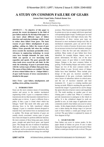
Stress on a Gear CompressionToothHertzian Fatigue(contact fatigueon both teeth)- on the unloaded sideTensionon the contact sideDriver -Surface Fatigue(only in the contactareas in tension)The tooth is loaded and stressed by:– Sliding contact causing surface fatigue damage– Rolling contact Hertzian fatigue damage– Bending, like a cantilever beam, that alwaysresults in deformation and can cause breakageNeville W. Sachs, P.E. (c) 20146
Tooth ContactsRollingSliding Tooth contact involves both rolling and sliding Understanding the action of this contact is a key tounderstanding how and why gears wear. With involute teeth, the teeth tend to slide early in theircontact with the relative proportion of rolling increasinguntil, at the pitch line the contact is pure rolling. As the teethgo out of mesh the sliding proportion continually increases.7Neville W. Sachs, P.E. (c) 2014
Three Stages of ContactGear tooth contact showing the varying rollingand sliding directionsContact PointActionInitial ContactDriverRollingSlidingAt the Pitch LineRollingSlidingJust Neville W. Sachs, P.E. (c) 2014
Gear DesignLooking at the stresses shown on theearlier slides, we see that when a gear isdesigned simultaneous bending, rolling,and sliding forces have to be considered.In addition, the design has to plan for theappropriate durability rating.9Neville W. Sachs, P.E. (c) 2014
Gear Dedendum CompressionWearHertzian Fatigue(contact fatigueon both teeth)- on the unloaded sideTensionon the contact sideDriver -Surface Fatigue(only in the contactareas in tension)On the dedendum of the driving tooth, as the driven toothslides downward, the driving tooth surface is subjected totension, surface fatigue results, and the tooth wears. Atthe same time, where the driven tooth addendum surfaceis in compression, fatigue can not occur.10Neville W. Sachs, P.E. (c) 2014
Design Standards The standards have changed about every 15 or soyears Currently AGMA 2001 and ISO 6336 are in wide use.(AGMA American Gear Manufacturers AssociationISO International Organization for Standardization) Both allow for wear, bending and pitting resistance withequation modifiers that are similar, but not identical. AGMA is basically experienced-based while the ISOstandard is more academically-based. AGMA ratings are more conservative. API (American Petroleum Institute) has a series ofstandards developed from the AGMA standardsspecifically for refinery and processing facilities.11Neville W. Sachs, P.E. (c) 2014
Design Standards The original North American design standard was theLewis Equation:Wt transmitted load in pounds (or N)S 1/3 tensile strengthWt (S x F x Y)/DpF Face widthYDp Lewis form factor – based on thepressure angle and # of teeth diametral pitch Pressure angle is very important.Larger pressure angle results inGearstubbier, stronger teeth, but almostalways more sliding and a little lowerefficiency.PitchDiameters The tendency has been to go tosmaller teeth to improve wear rates.PressureAngle12Neville W. Sachs, P.E. (c) 2014
Common GearsStraight CutSpur GearOriginal, noisyand roughHerringboneMost gears that looklike this are actuallydouble helicalBoth correct forthrust problemsHelicalDouble HelicalSmoother, butthrust loadedHelical and double helical gears have multiple teeth in meshat one time, resulting in smoother and quieter operation than13spur gears.Neville W. Sachs, P.E. (c) 2014
Some Other CommonGears Bevel - similar to a spur gear butdesigned for a right angle drive, tends tobe rough and noisy. Spiral Bevel - teeth are at anangle so more than one is in mesh,similar to a helical gear Hypoid - a variation on spiralbevel with the pinion centerline moved. Worm - unlike involute gears inthat the action only involves sliding14Neville W. Sachs, P.E. (c) 2014
Worm Gears Usually used in high reduction applications. Worm gear and worm wheel contact action ispure sliding with no rolling. Many lubricants used on spur and helicalgears are not suitable for worm gears bothbecause the sliding action results in anextreme example of boundary lubrication andbecause some common EP additives attackthe bronze worm wheels.15Neville W. Sachs, P.E. (c) 2014
How does a LubricantPrevent Wear?Part One SurfaceRatio of the two dimensions λPart Two Surface This sketch shows a greatly magnified view of two partsseparated by a lubricant film. The separation is importantbecause the greater the distance, the less the parts contacteach other and less wear occurs. The Greek symbollambda, λ, is usually used to denote the relative filmthickness. λ is a result of the viscosity, relative speed, and the shape(relative roughness) of the parts.
Rolling Element Contactand LubricationRolling element bearings and gearsin general industrial equipmentLoadPressures - As high as 2 GPa in thecontact areasElementClearance - In the range of 0.25 to 0.51µmExit RegionTravelLubricantInletFatigue ZoneMost Important Lubricant Properties - Hertzian(Film thickness 0.00004”)Viscosity, CleanlinessAction - Inlet zone viscositytransformation supports clearance
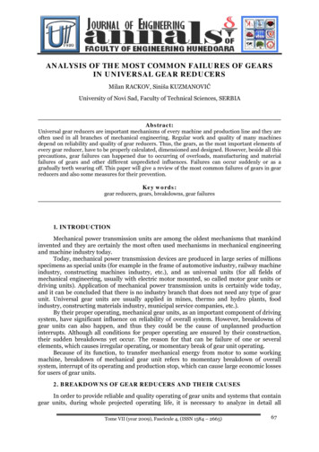
How Pressure AffectsViscosityAbsolute viscosity (cP)Pressure – Viscosity Relationshipfor a light Mineral OilASME Research Committee on Lubrication – Volume 11 100Pressure (1000 psi)120140
How does a LubricantPrevent Wear?Part One SurfaceRatio of the two dimensions λPart Two SurfacePart One SurfaceRatio of the two dimensions λPart Two SurfaceIn recent years improving the surface finish (superfinishing)has enabled gear tooth contact stresses to almost doublewithout having pitting.
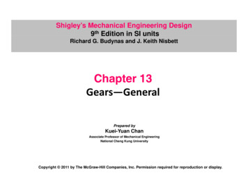
Relative Wear RateLubricantFilms andWearBoundaryMixed(Elastohydrodynamic) Hydrodynamic Lubrication - fullseparation of the two mating parts- low wear - usually on medium tohigh speed gears Boundary Lubrication - with thinto non-existent films and metal-tometal contact, additives are critical.(low speed and very heavilyloaded gears) Mixed (elastohydrodynamic) –bearings and many plant gearingapplications fall in this categoryHydrodynamicRelative Film ThicknessNeville W. Sachs, P.E. (c) 201420
Relative Wear RateChangingLubricantFilms andWear Newer synthetic lubricants (PAO,POE, PAG, PIB) with higherpressure-viscosity coefficients areeffecting better lubrication withimproved films, less heatgeneration, and higher efficiency. Newer additives are improving theboundary lubrication of low speedgears resulting in higher contactstresses without scuffing failure.(Scuffing is adhesive wear. Another termthat is used is amicRelative Film ThicknessNeville W. Sachs, P.E. (c) 201421
Stress causes ElasticDeformationDuring Operation the Teeth Deform The gear rim and hub also deform to someextent Changing loads will change this deformationand the contact patterns22Neville W. Sachs, P.E. (c) 2014
Quiz questions1. What is the basic metallurgy used for most modernindustrial and transportation gears?2. What is the diametral pitch?3. What is the gear module?4. There are several common ways of sizing gears. Whatare the primary differences between the AGMA 2001and the ISO 6336 methods?5. With what type of industrial gear metallurgy is pittingnot of immediate great concern?6. When pressure is put on oils, what happens to theirviscosity?7. In the shop, how should you check for the proper gearalignment of a set of reducer gears that have been inuse?23Neville W. Sachs, P.E. (c) 2014
Gear Inspection StepsGears are designed for strength and for durability1.2.3.4.With a bright light (and possibly a magnifying glass)look at both the active and inactive sides of the teeth,very carefully noting the contact patternsRotate the gears to see if the contact patterns andsurface conditions are consistentDetermine the tooth metallurgyDecide if the wear or damage is acceptable24Neville W. Sachs, P.E. (c) 2014
Q. Why are the contact patternsimportant?A. They show us the actual loads(forces) on the gear teeth.1.Both root and contact stresses will vary substantiallywith the accuracy of the meshing pattern.Contact on the inactive flank (unloaded tooth side) fromdriving forces will cause a huge increase in stresses.2.––With very good lighting, start by looking carefully at the activeflank contact all the way around the gear. (Does it vary?)Then look at the back (inactive side) of the teeth.25Neville W. Sachs, P.E. (c) 2014
Look at the Active ProfileLoad Intensity vs. visible Contact Pattern for three applications43RelativeContact 2Stress 10Ideal Stressfor Perfect ContactActual Stressfor Contact thatEnds at Tooth EdgeActual Stressfor Contact thatEnds at Mid-toothMeshPatternDon’t forget to rotate the gear to see how thepattern varies.26Neville W. Sachs, P.E. (c) 2014
A problem with contactpatterns As reducer marketing becomes more competitive,gear housings have become lighter. What can happen to gear alignment as that lighterhousing sees the same magnitude stress as anolder heavier housing?27Neville W. Sachs, P.E. (c) 2014
Stress AmplitudeUnderstanding GearDesign Loads3020Average tooth stress needed to rotate gear10Ideally the load shouldbe absolutely constantBut there are alwaysvariations and peakstress is criticalStress AmplitudeTime30Actual tooth loadsPeak tooth stressAverage tooth stressneeded to rotate gear2010Time28Neville W. Sachs, P.E. (c) 2014
Load VariationsStress AmplitudeLook at the difference in peak loads with these identicalgears! Same average load, but the upper one is muchmore highly stressed and will only last half as long.30Actual tooth loads2010TimeStress AmplitudePeak toothstress 2320Peak toothstress 1810TimeNeville W. Sachs, P.E. (c) 2014Average toothstress 1429
Look at the Wear onBoth Sides of these TeethMounted on the driveshaft of an oilfield gas engineGreenArrows30Neville W. Sachs, P.E. (c) 2014
More on Varying StressStress AmplitudeGraphing the load seen on that gear Peak tooth stressis now 34.30Average tooth stressneeded to rotate gearis still 1420100TimeNegative tooth loads shown by opposite side contactWith reversing loads the peak stress is much higher and therelative life of this gear is less than 15% of the earlier example!Same average load, incredible difference in life.31Neville W. Sachs, P.E. (c) 2014
Some Sources ofLoad Variations Coupling MisalignmentGear MisalignmentInput Torque ChangesPinion and Gear EccentricityMachining ErrorsTorsional Vibration and Resonances32Neville W. Sachs, P.E. (c) 2014
Tooth Alignment isCritical43RelativeContact 2Stress 10Ideal Stressfor Perfect ContactActual Stressfor Contact thatEnds at Tooth EdgeActual Stressfor Contact thatEnds at Mid-toothMeshPatternWith Hertzian fatigue stresses, the fatigue life is afunction of 1/load3.33 . As the tooth misalignmentbecomes worse, the life decreases rapidly. 33Neville W. Sachs, P.E. (c) 2014
Some Gear Materials WoodBronzeCast IronA Variety of Steels Hardened and Unhardened Plastics 34Neville W. Sachs, P.E. (c) 2014
Steel Gears - with VERYDifferent MetallurgiesCASE or SURFACE HARDENED TOOTHHard Case - usually betweenHRc 42 and HRc 60 Commonly – case at HRCSoft Core55-60 and core at HRC30-40THROUGH-HARDENED TOOTHSame hardness throughout(May or may not be hardened)Almost alwaysbelow HRC 40Case Hardening - may be from furnace, flame, induction, The case may be carburized, nitrided, carbonitrided, .35Neville W. Sachs, P.E. (c) 2014
Why the difference? Case (Surface) Hardened Gears More power in a smaller packageUsed on almost all mobile equipmentDemand closer tolerances in manufacturingSurface damage and impact loads can be deadly Through Hardened Gears Used on large gear sets and reducers wheregreat precision is difficult More tolerant of shock and impact loading Can tolerate substantial wear before failure Same hardnessHow do you tell the difference?throughoutHardness test or 36Neville W. Sachs, P.E. (c) 2014
North American Reducer GearMetallurgy – changes over the years Essentially every fixed reducer made before 1960had through harden
Design Standards The standards have changed about every 15 or so years Currently AGMA 2001 and ISO 6336 are in wide use. (AGMA American Gear Manufacturers Association ISO International Organization for Standardization) Both allow for wear, bending and pitting resistance with equation modifiers that are similar, but not identical. AGMA is basically experienced-based while .