Transcription
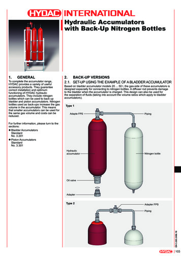
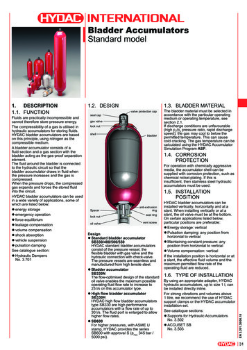
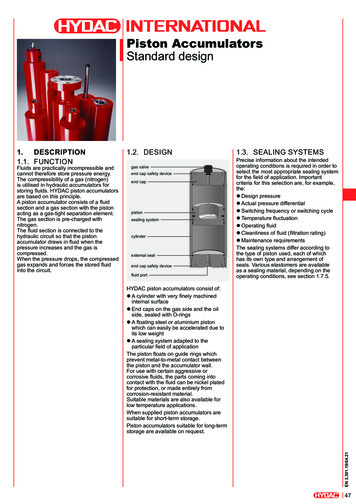
Piston AccumulatorsStandard designFluids are practically incompressible andcannot therefore store pressure energy.The compressibility of a gas (nitrogen)is utilised in hydraulic accumulators forstoring fluids. HYDAC piston accumulatorsare based on this principle.A piston accumulator consists of a fluidsection and a gas section with the pistonacting as a gas-tight separation element.The gas section is pre-charged withnitrogen.The fluid section is connected to thehydraulic circuit so that the pistonaccumulator draws in fluid when thepressure increases and the gas iscompressed.When the pressure drops, the compressedgas expands and forces the stored fluidinto the circuit.1.2. DESIGNgas valveend cap safety deviceend cappistonsealing systemcylinderexternal sealend cap safety devicefluid port1.3. SEALING SYSTEMSPrecise information about the intendedoperating conditions is required in order toselect the most appropriate sealing systemfor the field of application. Importantcriteria for this selection are, for example,the:z Design pressurez Actual pressure differentialz Switching frequency or switching cyclez Temperature fluctuationz Operating fluidz Cleanliness of fluid (filtration rating)z Maintenance requirementsThe sealing systems differ according tothe type of piston used, each of whichhas its own type and arrangement ofseals. Various elastomers are availableas a sealing material, depending on theoperating conditions, see section 1.7.5.HYDAC piston accumulators consist of:z A cylinder with very finely machinedinternal surfacez End caps on the gas side and the oilside, sealed with O-ringsz A floating steel or aluminium pistonwhich can easily be accelerated due toits low weightz A sealing system adapted to theparticular field of applicationThe piston floats on guide rings whichprevent metal-to-metal contact betweenthe piston and the accumulator wall.For use with certain aggressive orcorrosive fluids, the parts coming intocontact with the fluid can be nickel platedfor protection, or made entirely fromcorrosion-resistant material.Suitable materials are also available forlow temperature applications.When supplied piston accumulators aresuitable for short-term storage.Piston accumulators suitable for long-termstorage are available on request.EN 3.301.19/04.211.DESCRIPTION1.1. FUNCTION47
DesignApplication1 z For general accumulator operationwithout special requirementsContamination levelof fluidOptimised for applicationswith a high level ofcontaminationCommentApplication limitations:max. piston velocity: 0.5 m/s2 z Low-friction designz For high piston speedsz Depending on fluid, slow movementswithout stick-slip effectApplication limitations:max. piston velocity: 3.5 m/s3 z Low-friction designz Simple-to-fit sealsz Depending on fluid, slow movementswithout stick-slip effectFiltration:NAS 1638 – Class 6ISO 4406 - Class 17/15/12Application limitations:max. piston velocity: 0.8 m/s4 z Low-friction design with emergencysafety featuresz Depending on fluid, slow movementswithout stick-slip effectz Very low oil transfer to the gas sideEN 3.301.19/04.21Application limitations:max. piston velocity: 5 m/s481 guide ring forpistons with Ø 150 mm2 guide rings forpistons with Ø 180 mm
1.4. INSTALLATIONPOSITIONHYDAC piston accumulators operate inany position.Vertical installation is preferable with thegas side at the top, to prevent contaminantparticles from the fluid settling on thepiston seals. For hydraulic accumulatorswith certain piston position indicators,vertical installation is essential.1.5. TYPE OF INSTALLATIONFor strong vibrations and volumes above1 litre, we recommend the use of twoHYDAC mounting clamps, or more asappropriate, ideally in the end cap area.See catalogue section:z Mounting elements forhydraulic accumulatorsNo. 3.5021.6. ADVANTAGESz Complete range with nominal volumesup to over 3300 litres possiblez High ratios possible between pre-chargepressure and max. operating pressurez Economic solution using back-up gasbottles for low pressure differentialsz High flow rates possible; limitation: max.piston velocityz Power savingsz High level of efficiency of the hydraulicsystemz No sudden gas discharge when sealsare wornz Low space requirementsz Monitoring of the volume across theentire piston stroke or electrical limitswitchFurther advantages of using the lowfriction sealing system:z Minimum frictionz Also suitable for low pressuredifferentialsz No start-up frictionz Depending on fluid, slow movementswithout stick-slip effectz Low noise, no vibrationz High piston velocityup to 5 m/s for piston design 4z Improved accumulator efficiencyz Good service life of sealsdue to low wearz Suitable for large temperaturefluctuationsz Low maintenance requirements1.7. TECHNICALREQUIREMENTSHYDAC piston accumulators are suitablefor high flow rates (e.g. 1000 l/s).1.7.1 Effect of sealing frictionThe permitted piston velocity depends onthe sealing friction.Higher piston velocities are possible wherethere is less sealing friction.HYDAC piston accumulators of pistondesign 2 allow velocities ofup to 3.5 m/s.Oil velocityIn order to limit the pressure losses whenthe operating fluid is displaced, the flowvelocity should not exceed 10 m/s in thefitting cross-section.1.7.3 Function tests and fatigue testsFunction tests and fatigue tests are carriedout to ensure continuous improvement ofour piston accumulators.By subjecting the accumulators toendurance tests under realistic as wellas extreme working conditions, importantdata can be obtained about the longterm behaviour of the components. In thecase of piston accumulators, importantinformation on gas density and the servicelife of seals is gained from such tests.Vital data for use in accumulator sizing isgained by altering the working pressureand switching cycles.1.7.4 Gas chargingHydraulic accumulators must only becharged with nitrogen.Never use other gases.Risk of explosion!In principle, only use nitrogen of at leastClass 4.0 (filtration 3 µm).If other gases are to be used, pleasecontact HYDAC for advice.1.7.2 Permitted velocitiesGas velocityThe flow velocities in the gas sideconnection and pipe system shouldbe limited to 30 m/s when using pistonaccumulators of the back-up type. Gasvelocities of over 50 m/s should be avoidedat all costs.1.7.5 Working temperature and operating mediumThe permitted working temperature of a piston accumulator is dependent on the application limits of the metal materials and the pistonseal. Outside this temperature range, special materials must be used. The operating medium must also be taken into account.The following table displays a selection of elastomer materials including max. temperature range and a rough overview of resistant andnon-resistant fluids. Please contact us for help in selecting a suitable elastomer.Materialcode 1)Temperature rangeNBR2-20 C . 80 C5-40 C . 80 C8Standardapplication-30 C . 80 CSpecial application-40 C . 100 C-15 C . 160 orine rubber 61)2)Overview of the fluids 2)Resistant toz Mineral oil (HL, HLP)z Flame-retardant fluids from thegroups HFA, HFB, HFCz Synthetic esters (HEES)z Waterz Sea waterz Mineral oil (HL, HLP)z Flame-retardant fluids from theHFA groupz Mineral oil (HL, HLP)z Hydraulic fluids from the groupHFDz Synthetic esters (HEES)z Fuelsz Aromatic hydrocarbonsz Inorganic acidsSee section 2.2. Model code, material and piston code, material of seals incl. piston sealsOthers available on requestNot resistant toz Aromatic hydrocarbonsz Chlorinated hydrocarbons(HFD-S)z Amines and ketonesz Hydraulic fluids from the groupHFD-Rz Fuelsz Water and water-glycol mixtureHFCz Alkalisz Acidsz Amines and ketonesz Ammoniaz Skydrol and HyJet IVz SteamEN 3.301.19/04.21Materials49
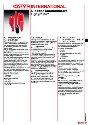
1.8. PISTON POSITION INDICATORSExamples of piston monitoring devices.Further options for determining the piston position and detailed technical data available on request.See also flyer:z Monitoring systems for hydraulic accumulatorsNo. 3.5061.8.1 Electrical limit switchWhat is measured?Max. or set fill level of the pistonaccumulatorHow are measurements taken?As point measurementsWhere to measure?Gas sideIdentification in the model code:A, B, C, ., depending on strokeProduct information:No. 100007690941.8.2 Magnetic flap indicationWhat is measured?Piston position via a magnet fastened to thecable that moves coloured flaps that can beread from the outsideHow are measurements taken?ContinuouslyWhere to measure?Gas sideIdentification in the model code:MProduct information:No. 10000769200EN 3.301.19/04.211.8.3 Cable tension measurement systemWhat is measured?Piston position via a cable fastened to thepiston501.8.4 Piston position switchWhat is measured?Piston position via ultrasonic measurementHow are measurements taken?As point measurementsWhere to measure?Fluid sideIdentification in the model code:UP.Product information:No. 100007691791.8.5 Linear position measurement systemWhat is measured?Piston position via elapsed timemeasurementHow are measurements taken?ContinuouslyWhere to measure?Gas sideIdentification in the model code:LProduct information:No. 100008106551.8.6 Laser linear position measurement systemWhat is measured?Piston position vialaser elapsed time measurementHow are measurements taken?ContinuouslyHow are measurements taken?ContinuouslyWhere to measure?Gas sideWhere to measure?Gas sideIdentification in the model code:SIdentification in the model code:LAProduct information:No. 10000641374Product information:No. 10000810664
SPECIFICATIONS2.1. EXPLANATIONS,NOTES2.1.1 Nominal volume [l]See table in section 3.2.2.1.2 Eff. gas volume V0 [l]This differs slightly from thenominal volume and forms thebasis of the calculations of theeffective fluid volume.See section 3.3.2.1.3 Effective volume V [l]Volume (fluid side) betweenoperating pressures p2 and p1.2.1.4 Permitted operatingtemperature of thehydraulic accumulator-10 C . 80 CStandard design, others on request2.1.5CountryCertificate codesEU member statesAustraliaBelarusCanadaChinaHong KongIcelandJapanKorea (Republic)New ZealandNorwayRussiaSouth AfricaSwitzerlandTurkeyUkraineUSACertificatecode (CC)UF 1)A6S1 1)A9A9UPA11TUA6S2UUA10SRegistration required in the individualterritories or provinces.Others on request1)2.1.6 NoticeAll work on HYDAC pistonaccumulators must only be carriedout by suitably trained staff.Incorrect installation or handlingcan lead to serious accidents.The operating instructionsmust be observed!No. 3.301.BAAssembly and repairinstructions are available forwork which may be carried outon the piston accumulator afterinstallation and commissioning,e.g. repair work.No. 3.301.MFurther information such asaccumulator sizing, safetyinformation and extracts fromthe acceptance specificationscan be found in the followingcatalogue section:z HYDAC AccumulatorTechnologyNo. 3.000Relevant PDF documents canbe accessed at:www.hydac.com » Downloads» Documents » AccumulatorDivision2.2. MODEL CODE ot all combinations are possible.NOrder example. For further information, please contact HYDAC.SK350 – 20 / 2212 U – 350 AAG – VA – 18 A – 1 – 050SeriesNominal volume [l]Material and piston code (MC)Piston design (see section 1.3.)Piston material1 aluminium2 carbon steel3 stainless steel 1)Material of cylinder and end cap1 carbon steel2 carbon steel with surface protection3 stainless steel 1)6 carbon steel (low temperature)Material of seals including piston seals2 NBR 2) / PTFE compound5 NBR 2) / PTFE compound6 FKM / PTFE compound8 NBR 2) / PUR9 special qualitiesCertification codeU European Pressure Equipment Directive (PED)Permitted operating pressure [bar]Fluid portType of connection (see Table 1)Standard or specification of the type of connection (see Tables 2 3)Size of connection (see Tables 4 5)Gas-side connection or gas valveType of connection (see Table 1)Standard or specification of the type of connection (see Tables 2 3)(no letter required with connection type V)Size of connection (see Table 4; 5 6)Piston diameter04 40 mm05 50 mm06 60 mm08 80 mm10 100 mm12 125 mm15 150 mm18 180 mm20253135495461 200 mm250 mm310 mm355 mm490 mm540 mm610 mmAdditional equipment*Detailed technical data on requestA electrical limit switch – 35 mm strokeB electrical limit switch – 200 mm strokeC electrical limit switch – 500 mm strokeE. other electrical limit switch, fixed or adjustableK protruding piston rodL linear position measurement systemLA laser linear position measurement systemM magnetic flap indicationS cable tension measurement systemU ultrasonic measurement systemUP. piston position switch(e.g. UP2 2 position switches, UPEX ATEX version)W limit switch with linear position measurement systemSafety equipment*1 burst disc (please give nominal pressure and temperature)2 gas safety valve3 temperature fusePre-charge pressure p0 [bar] at 20 C** If required, please state at time of ordering!1)Dependent on type and pressure rating2)Observe temperature ranges, see section 1.7.EN 3.301.19/04.212.51
Table 1, Connection typeCode letterABFHK, SVDescriptionThreaded connection (internal thread)Threaded connection (external thread)Flange connectionProtruding flangeCombination connection / special connectionGas valve typeTable 2, Threaded connection: standard or specificationCode letterABCDDescriptionThread to ISO 228 (BSP)Thread to DIN 13 or ISO 965/1 (metric)Thread to ANSI B1.1 (UN.-2B, seal SAE J 514)Thread to ANSI B1.20.3 (NPTF)Table 3, Flange connection: standard or specificationCode letterABCDEFDescriptionFlanges to DIN standards (pressure rating standard)Flanges to ANSI B 16.5SAE flange 3000 psiSAE flange 6000 psiHigh pressure block flange (Bosch-Rexroth) PN320High pressure block flange (AVIT, HAVIT) PN320Table 4, Threaded connection: sizesType listed Code letter, sizein Table 2 ABAG 1/8G CG 3/8M14x1.57/1620UNF1/4NPTFDG 1/2M16x1.51/220UNF3/8NPTFEG FGG 1 1/4M27x27/814UNF1-11 1/2NPTFHG 1 1/2M33x21 1/1612UNF1 1/4-11 1/2NPTFJG2M42x21 3/1612UNF11/2-11 1/2NPTFKG 2 1/2M48x21 5/1612UNF2-11 1/2NPTFLG3M60x21 5/812UNF2 1/2 NPTFCDN401 1/2" 1500 psiDDN502" 1500 psiEDN652 1/2" 1500 psiFDN803" 1500 psiGDN1001/2" 2500 psiHDN1251" 2500 psiJDN1501 1/2" 2500 psiKDN2002" 2500 psiL–2 1/2" 2500 psiTable 5, Flange connection: sizesType listed Code letter, sizein Table 3 ABADN15DN251/2" 1" B1500 psi1500 psiCDEF1/2"3/4"1"1 1/4"1 1/2"2"2 1/2"3"DN32DN40DN50DN65DN80DN100DN125DN150Table 6, Gas valve modelsEN 3.301.19/04.21Code letterABCDEF52DescriptionGas valve G3/4 male, with M28x1.5/M8Gas valve in end cap M28x1.5/M8Gas valve 1/2"-20UNF, male, with M16x2 (ISO 10945)Gas valve M14x1.5, male, with male M16x1.5 (Minimess)Gas valve G3/4 male, with 7/8-14UNF-VG8Gas valve in end cap M42x1.5/M123 1/2"4"5"––––DN 25–
3.2. DIMENSIONSNom. volume SeriesVmin. - max.[l]0.2 –0.5 –0.5 –1 –51015502.5 –702.5 – 1002.5 – 20010 – 20025 – 40025 – 750200 – 1300300 – 10350210350210350350210350210350210350Ø D1Ø 55Length calculation 1)L a (b t 2)min. - 885280280285346458100 731999111021543413449246962500 – 11000The lengths calculated are usually rounded up or down in 5 mm incrementsIntermediate weights can be calculated approximately depending on the length/diameter requiredOther pressures, volumes, approvals etc. possible on request.1)2)3.3. EFFECTIVE GAS VOLUME V0The gas volume V is larger than the nominal volume given in the table in section 3.2. bythe amount shown below.Piston Ø D1Piston 0346.2214.51412.705 1.2130.9993.0346.2214.51412.705EN 3.301.19/04.213.TECHNICAL DATA3.1. DRAWING53
3.4. VERSIONSPiston design 2 (depending on version aluminium or carbon steel)Carbon steel, NBR / PTFENominal 0SK35050SK210SK35075SK350100SK3501)2)Perm.Part no. 1) Ø D1 Ø D2operating 3pressure(PED)[bar][mm] [mm]39461333503946157150 180394615839461593503946161150 180394616439462603946262210180 2103586466312378939461953946196150 180394619835039463303112126180 2203946331312347339462973152988210180 210394629831234703946383 2)200 2353503946396 2)39463323213717350180 2203946333312350539463013823656210180 210394630232808443946399 2)200 2353946402 2)3503221083 2)250 3003946442 2)3946403 2)350200 2353946438 2)3484504 2)350250 3003946475 2)LGas sideFluid sideconnection connection[mm]ISO 228M28x1.5800 G 3/4gas valveM28x1.51365 G 3/4gas valveG 3/41050gas valveM28x1.52045 G 3/4gas valveG 3/41520gas valveG 3/41520gas valveG 3/41310gas valveG 3/42225gas valveG 3/42225gas valve1880142526752445G 3/4gas valveG 3/4gas valveG 3/4gas valveG 3/4gas valveG 3/4Weight[kg]7677G 3/4G 3/4G 1 1/2G 3/4G 1 1/2G 3/4G 3/4G 1 1/2G 3/4G 1 1/2G 3/4G 1 1/2G 3/4G 1 1/2G 3/4G 3/4G 1 1/2G 3/4G 1 1/2G 3/4G 1 1/2G 3/4G 1 1/2G 3/4G 1 1/2G 3/4G 1 2250262251203201228229339341302303512514 referred models, others on requestP Material and piston code (MC) 2112, see Model code, section 2.2.EN 3.301.19/04.21Notice:Dimensions, particularly lengths, are approximate and dependent on various factors (e.g.piston design, approval).The specified values are maximum values and must not be considered as referring to apermanent load. The tolerable pressure ratio is influenced by the geometry, temperature,fluid and flow rate as well as any gas losses caused by physical properties.54
4.SPARE PARTSPiston design 1DescriptionPiston assembly 2)consisting of:PistonSeal ringGuide ringCentre sealSeal kitconsisting of:Seal ringGuide ringCentre seal(Support ring)O-ringO-ringSeal ringO-ringPiston design 0180200220DescriptionPiston assembly 2)consisting of:PistonSeal ringGuide ringCentre sealSeal kitconsisting of:Seal ringGuide ringCentre seal(Support ring)O-ringO-ringSeal ringO-ringPiston design 3Qty.Item11211040 506071-73121(2)211140 506070-73(110)120180200220DescriptionPiston assembly 2)consisting of:PistonGuide ring 1)Seal ringSeal kitconsisting of:Guide ring 1)Seal ring(Support ring)O-ringO-ringSeal 20180200220Pressure-bearing parts cannot be supplied as spares.( ) for SK690 and standard SK, internal diameters 310 mm and above1)The bottom guide ring for internal diameters 180 mm and above2)Items (110), 120, 180, 200 and 220 are enclosed unassembled.EN 3.301.19/04.21Spare parts for piston design 4 are available on request.55
4.1. PISTON AND SEAL KITPiston design 1Piston design 2Piston design 3Piston assemblyPiston assemblyPiston assemblyPiston Ø[mm]6080100125150180200250310355490NBR / PTFEPart ��FKM / PTFEPart ��NBR / PTFEPart ��FKM / PTFEPart ��Seal kitPiston Ø[mm]6080100125150180200250310355490Piston Ø[mm]6080100125150180200250310355490NBR / PTFEPart 1135398030161953563823128989FKM / PTFEPart 398130161973540793128990NBR / PTFEPart 36326630162003632723104100FKM / PTFEPart 6730162013632733128991Seal kitPiston Ø[mm]6080100125150180200250310355490Piston Ø[mm]6080100125150180200250310355490NBR / PURPart 183016171–43230054323006Seal kitPiston Ø[mm]6080100125150180200250310355490NBR / PURPart 273016213437487237268883894300Pressure-bearing parts cannot be supplied as spares.Spare parts for piston design 4 are available on request.4.2. ASSEMBLY INSTRUCTIONSSpecial assembly sleeves are needed to assemble the piston and seals, see:Assembly and repair instructions for piston accumulatorsNo. 3.301.M5.NOTEEN 3.301.19/04.21The information in this brochure relatesto the operating conditions and fields ofapplication described.For applications and/or operatingconditions not described, please contactthe relevant technical department.Subject to technical modifications.56HYDAC Technology GmbHIndustriegebiet66280 Sulzbach/Saar, GermanyTel.: 49 (0) 68 97 / 509 - 01Fax: 49 (0) 68 97 / 509 - 464Internet: www.hydac.comE-mail: speichertechnik@hydac.com
K protruding piston rod L linear position measurement system LA laser linear position measurement system M magnetic flap indication S cable tension measurement system U ultrasonic measurement system UP. piston position switch (e.g. UP2 2 position switches, UPEX ATEX version)