Transcription
How To Create A Secure Network With Allied TelesisManaged Layer 3 SwitchesIntroductionAllied Telesis switches include a range of sophisticated security features at layer 2 and layer 3.This How To Note describes these features and includes brief examples of how to configurethem.The implementations shown in this How To Note should be thought of as industry-standardbest practices.ContentsIntroduction . 1Which products and software versions does this information apply to? . 2Securing the device . 3Protecting the network .Protecting against packet flooding .Protecting against rapid MAC movement .Controlling multicast traffic .3367Managing the device securely . 9Using Secure Shell (SSH) . 9Using SSL for secure web access . 10Using SNMPv3 . 10Whitelisting telnet hosts . 12C613-16103-00 REV AIdentifying the user .IP spoofing and tracking .Rejecting Gratuitous ARP (GARP) .DHCP snooping .Using 802.1x port authentication .1414151517Protecting the user .Using private VLANs .Using local proxy ARP and MAC-forced forwarding .Using IPsec to make VPNs .Protecting against worms .1818192425www.alliedtelesis.com
Which products and software versions does this information apply to?Appendix: Configuration scripts for MAC-forced forwarding example .Edge switch 1 .Edge switch 2 .Edge switch 3 .Access Router .2727282930For information about the AlliedWare firewall, see the Firewall chapter of your SoftwareReference, and the following How To Notes:zHow To Configure Some Basic Firewall And VPN ScenarioszHow To Apply Firewall Policies And RulesHow To Notes are available from spx.Which products and software versions does thisinformation apply to?This How To Note applies to the following Allied Telesis switch series:zAT-8600zAT-8700XLzAT-8800zRapier izSwitchBladezAT-9800zAT-8948 and x900-48zAT-9900zAT-9900s and x900-24Some features are only available on some switches and/or some software versions.Therefore, when this How To Note describes each feature, it lists the applicable switches andversions.Create A Secure Network With Allied Telesis Managed Layer 3 Switches2
Securing the deviceSecuring the deviceThe first step towards making a secure network is to securethe networking equipment itself.ProductsThere are two aspects to this. Firstly, physical security isvital—lock your networking equipment away.Software VersionsAll switches listed on page 2AllSecondly, straight after powering up any new piece ofnetworking equipment, change the default administrator user’s password. On an AlliedTelesis managed layer 3 switch, the default user is “manager”. To change the password, usethe following command:set user manager password new-password The default password is well-known. If you do not change it, anyone with physical or IP accesscould reconfigure the switch.Protecting the networkThis section describes layer 2 based methods for controlling the negative impact ofmisconfigured devices and misuse of the network. These solutions work at the Ethernet levelof a packet and cause no degradation in the switch's throughput.You can protect your network against the following:ztraffic storms (“Protecting against packet flooding” on page 3)zexcessive MAC address learning (“Protecting against rapid MAC movement” on page 6)zunwanted multicast traffic (“Controlling multicast traffic” on page 7)Protecting against packet floodingService providers are often vulnerable to traffic storms, primarily when incorrectlyconfigured customer equipment is directly connected to the provider. Storms overwhelm asubnet, and all of the switches in that subnet, with traffic. Such misconfiguration can quicklylead to widespread outages and compromise guaranteed service levels.Storms are a reality in any network. They can occur by accident, maliciously, or when anetwork device fails. They occur naturally in a network where switches are connected morethan once to the same VLAN, so administrators must employ a method to prevent theseswitch loops.Spanning Tree Protocol based solutions are the most common method of preventing loops.However, incorrect configuration or other network issues can cause STP to fail. For example,if a single switch in the VLAN does not have STP enabled, the STP tree will not convergeproperly. Spanning tree protocols can even fail if a broadcast storm drowns out STPmessages.Create A Secure Network With Allied Telesis Managed Layer 3 Switches3
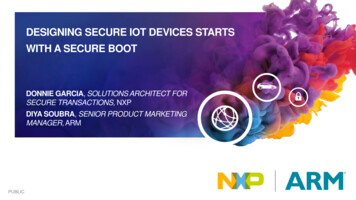
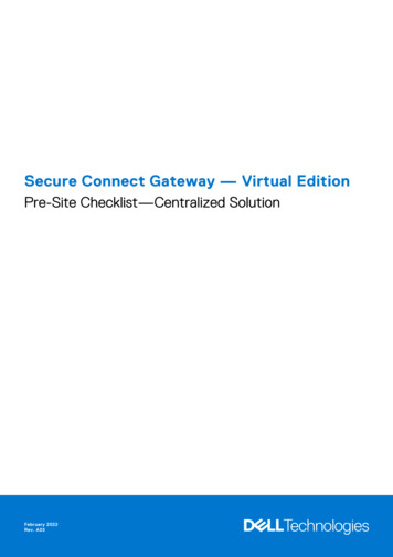
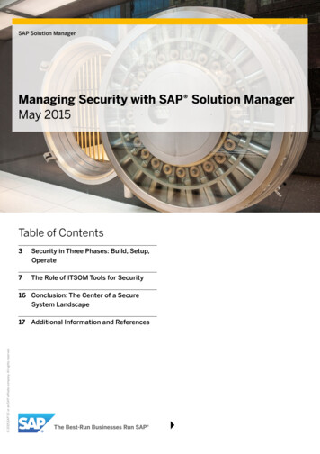
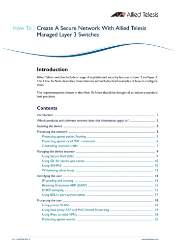
Protecting the networkService providers need to prevent storms from disrupting services to customers. AlliedWareoffers the following options for mitigating storms:zlimiting broadcasts and multicasts on a port (“Bandwidth limiting” on page 4)zdetecting a storm and disabling that port or VLAN (“Using QoS policy-based stormprotection” on page 5)Bandwidth limitingARP packets are the most frequent trigger for broadcaststorms. One ARP packet is flooded around and around anetwork, crowding out all other traffic.ProductsAll switches listed on page 2Software VersionsYou can use a simple Quality of Service (QoS) configurationto match ARP packets and make sure that when a broadcaststorm occurs, the effect is minimised.AllISP switchWhen ISP switch hasno bandwidth control:misconfiguredcustomer switchflood of ARPsport48ISP switchWhen ISP switch hasbandwidth limiting:misconfiguredcustomer switchflood of To limit the bandwidth for ARPs:1. Create a classifier to match ARP packets.2. Create a QoS framework of policy, traffic class, and flow group. In the traffic class settings,specify the maximum bandwidth for ARP traffic.3. Apply the policy—and therefore the bandwidth limit—to one or more ports.ExampleThe following configuration limits ARP packets to 100kbps on port 48.create classifier 1 protocol 0806 ethformat ethii-untaggedcreate qos policy 1create qos trafficclass 1 maxbandwidth 100create qos flowgroup 1add qos policy 1 trafficclass 1add qos trafficclass 1 flowgroup 1add qos flowgroup 1 classifier 1set qos port 48 policy 1Create A Secure Network With Allied Telesis Managed Layer 3 Switches4
Protecting the networkUsing QoS policy-based storm protectionPolicy-based storm protection lets you specify one of arange of actions for the switch to take when it detects abroadcast storm. It is a part of the QoS functionality.Policy-based storm protection is more powerful than simplebandwidth limiting. It lets you restrict storm damage towithin the storming VLAN, and it gives you the flexibility todefine what traffic rate makes a broadcast storm.ProductsAT-8948x900-48 SeriesAT-9900 SeriesAT-9924Tsx900-24 SeriesSoftware Versions2.8.1 and laterConfigurationTo use storm protection:1. Turn on the switch enhanced mode qoscounters, unless it is already enabled. After this,you need to restart the switch.2. Create a classifier to match the desired traffic. To match all broadcast packets specify adestination MAC address of ff-ff-ff-ff-ff-ff.3. Create a QoS traffic class and define the following storm protection settings in it:zWindow (stormwindow) specifies how often the switch measures traffic to decidewhether to activate storm protection (in seconds).zRate (stormrate) specifies the amount of traffic per second that must be exceededbefore the switch takes action.zAction (stormaction) specifies what the switch does when it detects a storm:Link Down (linkdown) makes the switch physically disable the port on which thestorm is occurring, so that the link goes down.Port Disable (portdisable) makes the switch logically disable the port on which thestorm is occurring, leaving the link up.VLAN Disable (vlandisable) makes the switch block traffic only on the VLAN onwhich the storm is occurring.zTimeout (stormtimeout) specifies the number of seconds that the port remainsdisabled for.4. Create the rest of the QoS framework: a flow group and policy. Add the classifier to theflow group, the flow group to the traffic class, and the traffic class to the policy.5. Apply the policy—and therefore the storm protection—to one or more ports.The procedure above applies storm protection to classified traffic, and uses a classifier toselect all broadcast traffic. This is the most common approach. If you want to, you can insteadclassify to select important non-broadcast traffic and apply storm protection to unmatchedtraffic. Unimportant or unwanted unicast and multicast traffic then counts towards the stormcalculations.To apply storm protection to unclassified traffic, configure storm protection on the defaulttraffic class in the QoS policy settings. Use the parameters dtcstormwindow,dtcstormrate, dtcstormaction, and dtcstormtimeout.Create A Secure Network With Allied Telesis Managed Layer 3 Switches5
Protecting the networkExampleThe following example applies storm protection to classified broadcast traffic on port 1. Ifthere is a storm, it takes the link down for 60 seconds.set switch enhancedmode qoscountersReboot after turning on enhanced mode.create classifier 1 macdaddr ff-ff-ff-ff-ff-ffcreate qos trafficclass 1 stormstatus enable stormwindow 100stormrate 100 stormaction linkdown stormtimeout 60The rest of the QoS configuration is as normal, so:create qos flowgroup 1add qos flowgroup 1 classifier 1add qos trafficclass 1 flowgroup 1create qos policy 1add qos policy 1 trafficclass 1set qos port 1 policy 1You can view matching traffic at the port level with the command:show qos port 1 count trafficclassProtecting against rapid MAC movementRapid MAC movement protection detects excessive MACaddress learning on a specific switch port. Once excessivelearning is detected, the switch stops learning MACaddresses via the affected port.ProductsAT-8948x900-48 SeriesAT-9900 SeriesRapid MAC movement mostly occurs because of abroadcast storm, when one packet is storming around alayer 2 network. Rapid MAC movement protection issimpler to configure than QoS policy-based stormprotection but is not guaranteed to stop all the varieties ofbroadcast storm.AT-9924Tsx900-24 SeriesSoftware Versions2.8.1 and laterRapid MAC movement protection is on by default. The default action is to disable learning for1 second. This gives the CPU of the switch some idle time, which may let a fast STP-typeprotocol converge. You can change the amount of idle time to suit your network, or select adifferent action.Configurationon one ormore portsTo customise the protection:1. Set the parameters in the following command:set switch port ports thrashaction {learndisable linkdown none portdisable vlandisable} thrashtimeout {none 1.86400}vlanstatustrap {on off}The parameter thrashaction specifies the switch’s response to rapid MAC movement:zlearndisable makes the switch temporarily disable learning on the port.zlinkdown makes the switch physically disable the port, so that the link goes down.zportdisable makes the switch logically disable the port, leaving the link up.zvlandisable makes the switch block traffic on only the VLAN on which the rapidlearning occurred.Create A Secure Network With Allied Telesis Managed Layer 3 Switches6
Protecting the network2. Set the sensitivity in detecting rapid MAC movement, by using the following command totell the switch how many times a MAC address can move ports in one second:set switch thrashlimit 5.255Configurationon trunkgroupsRapid MAC movement protection also works with trunk groups. If one switch in a trunk fails,the switches probably cannot negotiate STP or any other trunks that they belong to. Thisimmediately causes a broadcast storm. Rapid MAC movement protection on the otherswitch in the trunk group detects such a storm because flooding of the same packet occurson all trunk ports connected to the failed switch.For a static trunk, to make use of rapid MAC movement protection, create the trunk andspecify the optional thrashaction and thrashtimeout parameters:create switch trunk name port ports thrashaction {learndisable linkdown none portdisable vlandisable} thrashtimeout {none 1.86400}For a dynamic trunk using LACP, enable LACP, add ports, and set the optional thrashactionand thrashtimeout parameters:enable lacpadd lacp port ports set lacp thrashaction {learndisable linkdown none portdisable vlandisable} thrashtimeout {none 1.86400}Controlling multicast trafficIn a busy network, or one that has subscription-only access to multicast services, tightper-port control of multicast traffic is required. IGMP makes multicasting fairly efficient, butthe extra control offered by AlliedWare helps increase efficiency.When multicasting, it is essential to avoid filling the network with unnecessary multicast dataand to make sure that the clients who join a group are entitled to receive it. It is alsoimportant to minimise delays in joining a group and to efficiently handle those who leave agroup.The following sections outline some of the IGMP controls that are particularly relevant forsecurity. For detailed information on how to control IGMP in the network, see How ToConfigure IGMP for Multicasting on Routers and Managed Layer 3 Switches. This How To Note isavailable from spx.IGMP snoopingIGMP snooping is enabled by default on Allied Telesismanaged layer 3 switches. IGMP snooping monitors thestreams and clients involved in each multicast group,independent from IP itself. A snooping switch ensures thatonly ports that are interested in a group are sent it. Thisbasic level of management works in tandem with thesubnetwork's IGMP querier and makes sure that the queriergets notified of any client who wants to join the group.Create A Secure Network With Allied Telesis Managed Layer 3 SwitchesProductsAll switches listed on page 2Software VersionsAll7
Protecting the networkIGMP filteringIGMP filtering lets you dictate exactly which multicastgroups a specific port can receive, by creating a filter list andapplying it to the port. Different ports may have differentfilter lists applied to them.ProductsAll switches listed on page 2that support 2.7.5 or laterSoftware VersionsIf desired, you can select the type of message to filter. Bydefault, filters apply to IGMP reports. You can create extraentries to also filter queries (type query) and leavemessages (type leave).Configuration2.7.5 or laterFor each port:1. Work out which groups you want users on the port to be able to join.2. Create an IGMP filter.3. Create entries to allow the appropriate groups (action include).Note:The order of entries in a filter is important. When IGMP tries to match a messageto a filter, it performs a linear search of the filter to find a matching entry. It trieseach entry in turn, and stops processing the filter after the first match it finds.4. Create an entry to block all groups (action exclude). Give this entry a higher entrynumber than entries for the included groups.5. Apply the filter to the port.ExampleTo stop the user attached to port 1 from joining any group except 224.12.13.14:create igmp filter 1add igmp filter 1 entry 1 group 224.12.13.14 action includeadd igmp filter 1 entry 2 group 224.0.0.0-239.255.255.255action excludeset switch port 1 igmpfilter 1IGMP throttlingThrottling limits the number of multicast groups that anindividual port can join.ExampleTo limit port 2 to a total of 6 groups:set switch port 2 igmpmaxgroup 6igmpaction replaceCreate A Secure Network With Allied Telesis Managed Layer 3 SwitchesProductsAll switches listed on page 2that support 2.7.5 or laterSoftware Versions2.7.5 or later8
Managing the device securelyManaging the device securelyIn Ethernet and broadcast networks the privacy of traffic is not guaranteed. Hubs andnetworks outside the administrator's control may leak sensitive data to unwanted recipients.A hacker may even be able to force a switch to flood unicast traffic.Because you cannot guarantee traffic privacy, you cannot be certain that managementsessions are private. Therefore, you should always use encrypted sessions when remotelyadministering network equipment, even in networks that you know well. The simplest way toachieve this is with Secure Shell (SSH).This section describes secure management:z“Using Secure Shell (SSH)” on page 9z“Using SSL for secure web access” on page 10z“Using SNMPv3” on page 10Then the section ends by describing how to limit telnet access if you need to use telnetinstead of one of the recommended secure options (“Whitelisting telnet hosts” on page 12).When you are using a secure management scheme, we recommend that you block all telnetaccess to the switch, by disabling the telnet server:disable telnet serverUsing Secure Shell (SSH)The Secure Shell (SSH) protocol is most simply described asan encrypted form of Telnet.ConfigurationProductsAll switches listed on page 21. Add a security officer to your switch’s list of users.Software Versions2. Create encryption keys for SSH to use.All3. Enable the SSH server.4. Add the security officer to the list of SSH users and specify a password for it. Only usersin this list can use SSH to access the switch.5. Enable system security.Enabling system security makes telnet unavailable as an administrative interface—once youhave configured SSH, you have to use it.ExampleTo configure SSH access for the security officer called “secoff”:add user secoff password securepass privilege security telnet yeslogin yescreate enco key 0 type rsa length 1024 description "Host Key"form sshcreate enco key 1 type rsa length 768 description "Server Key"form sshenable ssh server serverkey 1 hostkey 0 expirytime 1logintimeout 60add ssh user secoff password sameordifferentpasswordenable system securityCreate A Secure Network With Allied Telesis Managed Layer 3 Switches9
Managing the device securelyUsing SSL for secure web accessIf you prefer to configure the switch using the convenientweb-based GUI, then this is unencrypted by default. SSL letsyou use the GUI securely, by using HTTPS instead of HTTP.Configuration1. Add a security officer to your switch’s list of users.2. Create an encryption key for SSL to use.3. Create a self-signed PKI certificate, or load a certificategenerated by a Certificate Authority (CA) if you haveone.ProductsAll switches listed on page 2,except AT-8948 and x900-48Series which have nographical user interfaceSoftware VersionsAll4. Add the certificate to the certificate database.5. Turn security on for the HTTP server.6. Enable system security.Once you have configured SSL, HTTPS connections to the device are available only onport 443.ExampleTo allow the security officer called “secoff” to browse securely to the GUI, using a self-signedcertificate:add user secoff password secoff privilege securityofficerlogin yescreate enco key 0 type rsa length 1024set system distinguishedname "cn switch1,o my company,c us"create pki certificate cer name keypair 0 serialnumber 12345subject "cn 172.30.1.105,o my company,c us"add pki certificate cer name location cer name.cer trust yesset http server security on sslkey 0 port 443enable system securityUsing SNMPv3Traditionally, SNMP has been a popular but insecure way tomonitor networks.Allied Telesis devices are SNMPv3 compliant. By usingSNMPv3, you can authenticate SNMP users and restricttheir network access to parts of the network. SNMPv3 isvery flexible, as the examples in this section show.ConfigurationProductsAll switches listed on page 2Software Versions2.6.4 and later1. Enable SNMP.2. Set up one or more SNMP views. Views list the objects in the MIB that users can see.3. Set up one or more groups and add the groups to the views. Each group is a collection ofusers who have the same access rights.4. Set up one or more users and add them to the groups. Authentication parameters are sethere.5. Set up a traphost profile, for trap messages to be remotely sent to. This is not compulsorybut we recommend it.Create A Secure Network With Allied Telesis Managed Layer 3 Switches10
Managing the device securelyExamplesTo allow the user “steve” full read, write and notify SNMP access to the switch:enable snmpadd snmp view full oid 1.3.6.1 type includeadd snmp group super-users securitylevel authPriv readview fullwriteview full notifyview fulladd snmp user steve group super-users authprotocol md5authpassword cottonsox privprotocol des privpassword woollytopTo also give the user “jane” read and notify access to everything on the switch, add thefollowing commands:add snmp group users securitylevel authNoPriv readview fullnotifyview fulladd snmp user jane group users authprotocol md5authpassword redjeansTo also give the user “paul” unauthenticated read access to everything on the switch exceptBGP, add the following commands:add snmp view restricted oid 1.3.6.1 type include# exclude bgp by specifying either mib bgp or oid 1.3.6.1.2.1.15:add snmp view restricted mib bgp type excludeadd snmp group restricted-users securitylevel noAuthNoPrivreadview restrictedadd snmp user paul group restricted-usersTo also send traps securely to the PC with IP address 192.168.11.23 for user “steve” to see,add the following commands:add snmp targetparams netmonpc securitylevel authPriv user steveadd snmp targetaddress nms ip 192.168.11.23 udp 162params netmonpcFor more information about the above examples, see How To Configure SNMPv3 On AlliedTelesis Routers and Managed Layer 3 Switches, available from spx. This How To Note also explains SNMPv3 concepts in detail, includingusers, groups and views.Create A Secure Network With Allied Telesis Managed Layer 3 Switches11
Managing the device securelyWhitelisting telnet hostsFor any remote management of a network device, Allied Telesis recommends you use SSH,Secure HTTP (SSL), or SNMPv3. Therefore, we recommend you block all telnet access tothe switch by disabling the telnet server. However, if you persist with telnet, you should makea whitelist of the hosts that are permitted to telnet to the switch. This does not make telnetsecure, but it does reduce the associated risks.Building a whitelist through layer 3 filtersOn Rapier, Rapier i, AT-8800, AT-8700XL and AT-8600Series switches, use layer 3 filters to build a whitelist.Configuration1. Create a filter match definition that specifies destinationIP address, protocol and destination TCP port as thecriteria that the filter will match. The switchautomatically assigns this filter an ID of 1 (unless otherlayer 3 filters already exist).2. Create a filter entry that specifies the switch’s IP addressas the destination address, TCP as the protocol and 23as the port. Give it an action of deny.ProductsAT-8600 SeriesAT-8700XL SeriesRapier i SeriesRapier SeriesAT-8800 SeriesSoftware VersionsAll3. Create another filter match definition with source and destination IP addresses, both with32-bit masks.4. Create filter entries for the second filter. In each entry, specify a permitted host as thesource and the switch’s IP address as the destination. Give the entries an action of nodrop.The first filter blocks (action deny) any incoming telnet packets with the switch’sdestination IP address. The second filter reverses the first filter by undoing the previousdenial of IP access to the switch—but only for the permitted source IP addresses.ExampleTo permit only the host with IP address 172.30.1.144 to telnet to the switch 172.28.40.70:add switch l3filter match dipaddress,protocol,tcpdport dclass 32add switch l3f 1 entry protocol tcp dipaddress 172.28.40.70tcpdport 23 action denyadd switch l3filter match dipaddress,sipaddress sclass 32dclass 32add switch l3filter 2 entry sipaddress 172.30.1.144dipaddress 172.28.40.70 action nodropCreate A Secure Network With Allied Telesis Managed Layer 3 Switches12
Managing the device securelyBuilding a whitelist through QoSOn AT-8948, AT-9900, AT-9900s, and x900 Series switches,use classifiers to build a whitelist and QoS to apply it.Configuration1. Create classifiers to match telnet traffic from permittedIP addresses to the switch’s IP address.ProductsAT-8948x900-48 SeriesAT-9900 Series2. Create a classifier to match all telnet traffic to theswitch’s IP address.AT-9924Tsx900-24 Series3. Create a flow group and add the classifiers for permittedtraffic to it.Software Versions2.7.3 and later4. Create a second flow group with a higher ID number andadd the classifier that matches all telnet traffic to it.5. Create the rest of the QoS framework—traffic class and policy.6. Apply the policy to all ports to stop telnet from all directions.QoS is an incredibly versatile hardware-level packet filtering mechanism. For moreinformation about setting up QoS on these switches, see How To Configure QoS On AT-8948,AT-9900, AT-9900s And x900 Series Switches. This How To Note is available to.aspx.ExampleTo permit only the host with IP address 172.30.1.144 to telnet to the switch 172.28.40.70:create classifier 1 ipsa 172.30.1.144/32 ipda 172.28.40.70/32tcpd 23create classifier 2 ipda 172.28.40.70/32 tcpd 23create qos flowgroup 1 action forwardcreate qos flowgroup 2 action discardcreate qos trafficclass 1create qos policy 1add qos flowgroup 1 classifier 1add qos flowgroup 2 classifier 2add qos trafficclass 1 flowgroup 1add qos trafficclass 1 flowgroup 2add qos policy 1 trafficclass 1set qos port all policy 1Create A Secure Network With Allied Telesis Managed Layer 3 Switches13
Identifying the userIdentifying the userThis section describes methods for authorising and tracking users and preventing them fromchanging their identity on the network.IP spoofing and trackingUnknown users who attempt to change IP address—to circumvent billing or to hide theiridentity—can be a problem for administrators.Changing IP address for malicious reasons is most commonly called IP spoofing, and is alsoknown as ARP spoofing, ARP poisoning, and ARP poison routing (APR). The net result is thesame for all of these: the victim ends up with false information in its ARP table.The trouble with ARPIP Spoofing takes advantage of the inherently insecure design of ARP. In an Ethernet network,a client may use a Gratuitous ARP (GARP), or merely send an ARP request or reply withfalse information, to announce a phoney identity to the local subnet.A phoney announcement may be made in a number of ways for a number of reasons. Thefollowing table briefly explains these factors.If the ARP or GARP packet contains.Then.MAC that does not exist on network andIP address that does not exist on networkthe attacker may be trying to fill up the IP ARP tableso that the subnet’s router cannot learn moreaddresses. As a result, return (routed) traffic maynot be forwarded.MAC that is owned by attacker andIP address that does not exist on networkthe attacker is using an IP address that theadministrator has not assigned and so may be tryingto avoid traceability.MAC that is owned by attacker andIP address that is owned by another hostthe attacker is trying to intercept traffic destined forthis host.MAC that is owned by attacker andIP address that is owned by the subnet routerthe attacker is trying to intercept all traffic leavingthe subnet.MAC does not exist on network andIP address t
zdetecting a storm and disabling that port or VLAN ("Using QoS policy-based storm protection" on page 5) Bandwidth limiting ARP packets are the most frequent trigger for broadcast storms. One ARP packet is flooded around and around a network, crowding out all other traffic. You can use a simple Quality of Service (QoS) configuration