Transcription
Behaviour of Water Drop on the Insulator Surfaceand Study of Electric Field Distribution onParallel Insulators under DCVon der Fakultät für Maschinenbau, Elektrotechnik und Wirtschaftsingenieurwesen derBrandenburgischen Technischen Universität Cottbus-Senftenberg zur Erlangung desakademischen Grades eines Doktors der Ingenieurwissenschaften genehmigteDissertationVorgelegt vonMaster IngenieurNaresh Kumar ChallagondlaGeboren am 02. June 1985 in Sriramgiri, IndienVorsitzender: Prof. Dr.-Ing. Harald FienGutachter 1: Prof. Dr.-Ing. Harald SchwarzGutachter 2: Prof. Dr.-Ing. Dr. h. c. Heinz-Helmut SchrammTag der mündlichen Prüfung: 16. Februar 2015
AcknowledgementsThis work is carried out at the department of Energy Distribution and High VoltageEngineering at Brandenburg University of Technology Cottbus- Senftenberg.First and foremost, I would like to express my special appreciation and thanks to myPhD advisor Prof. Dr.-Ing. H. Schramm for providing me with the opportunity to completemy PhD thesis. He has been supportive since the days I began working on insulators. Iam very grateful for his patience, motivation, enthusiasm and immense knowledge inhigh voltage engineering. He has been actively interested in my work and has alwaysbeen available to advise me.I would like to thank Dr. Kynast from Siemens AG for his encouragement, constructivesuggestions and interesting discussions. The financial support is provided by SiemensAG. This is gratefully acknowledged.My sincere thanks to Prof. Harald Schwarz and Prof. Harald Fien for initiating thegraduate program at TU Cottbus, participating in my dissertation committee andspending time to review my dissertation.I thank my parents and brother for providing me support whenever I needed it. My hardworking parents have given up many things for me to be in Germany. I would not havemade it this far without them. In final year of my PhD I married the best person out therefor me. She has been a true and great supporter. I truly thank my wife for sticking to myside, even when I was irritable and depressed.i
AbstractWith the recent developments in electrical transmission system, HVDC transmission forlong distances has become feasible. With this development, many insulators are beingused in HVDC system. Different kinds of insulators are situated at different places(example: desert, near to sea, agriculture area, etc.) so they will get expose to differenttypes of pollution. Pollution affects the behavior of insulation in terms of breakdown andwithstand capability. The application experience of insulators under HVDC conditions islimited. There is a necessity to understand the flashover performance and to recognizekey parameters in the design and dimensioning of insulators used under HVDCconditions. This dissertation presents the difference between the analysis of partialbreakdowns at AC and DC.The dissertation explains the behavior of a water drop on insulator shed surfaceenergized with DC. It deals with the moving water drop and hanging drop at the edge ofthe shed.There are many situations where insulator structure should be in parallel. For example,the structure of insulators in vertical disconnector equipment often is parallel. Ifinsulators are arranged in parallel, then the behavior of the electric field is totallydifferent. It is important to know the behavior of these insulators used in HVDC system.This report also explains the pollution and non-pollution behavior of parallel insulatorsenergized with DC.The results can be a source of information to optimize the design and dimensioning ofHVDC insulators, especially in pollution conditions.Key words: HVDC, High-Voltage insulators, pollution performance, water drop behavior,parallel insulators, Ansys Maxwell.ii
KurzfassungMit den neuen Entwicklungen im Bereich der elektrischen Übertragungsnetze wurde dieHGÜ für große Entfernungen ermöglicht. Durch diese Entwicklungen werden vieleIsolatoren im HGÜ-System verwendet. Unterschiedliche Arten von Isolatoren werden anverschiedenen Orten eingesetzt (z.B.: in der Wüste, in der Nähe vom Meer, imlandwirtschaftlichen Bereich, etc.), wodurch sie auch unterschiedlicher Verschmutzungausgesetzt werden. Die Verschmutzung beeinflusst das Verhalten der Isolation in Bezugauf ihre Belastbarkeit und ihr Versagen. Die praktischen Erfahrungen mit Isolatorenunter HGÜ-Bedingungen sind begrenzt. Es ist erforderlich das Überschlagverhalten zuverstehen und die wichtigen Parameter für die Auslegung und Dimensionierung vonIsolatoren unter HGÜ Bedingungen zu erkennen. Diese Dissertation stellt denUnterschied zwischen Teilentladungen bei AC und DC dar.Die Dissertation erklärt das Verhalten eines Wassertropfens auf der Schirm Oberflächedes Isolators bei angelegter DC Spannung. Sie befasst sich mit bewegtenWassertropfen und hängenden Tropfen am Rand des Schirms.Es gibt viele Situationen, in denen eine parallele Isolator-Struktur erforderlich ist. ZumBeispiel kommt in vertikalen Trennschaltern eine parallele Struktur der Isolatoren vor.Wenn Isolatoren parallel angeordnet sind, ist das Verhalten des elektrischen Feldesvöllig unterschiedlich. Es ist wichtig, das Verhalten der Isolatoren in der HGÜ-Anlage zukennen. Dieser Bericht erklärt auch das Verhalten bei der Verschmutzung und imverschmutzungsfreien Zustand von parallelen Isolatoren unter DC Spannung.Die Ergebnisse können als Informationsquelle verwendet werden, um die Auslegungund Dimensionierung von HGÜ-Isolatoren, insbesondere bei Verschmutzung, zuoptimieren.Schlüsselwörter: HGÜ, Hochspannungsisolatoren, Verhalten bei Verschmutzung,Verhalten bei Wassertropfen, parallele Isolatoren, Ansys Maxwell.iii
ContentsAcknowledgements . iAbstract . iiKurzfassung. iii1 Introduction . 11.1 General Information . 11.2 Organization of Work . 52 Basic Knowledge . 72.1 Types of Insulators . 72.1.1 Line Insulators . 72.1.2 Post Insulators . 112.2 Classes of Pollution. 122.3 Types of Environments . 132.4 Necessities for the Study of Polluted Insulators under DC . 153 Modeling and Simulation Tools . 173.1 Simulation Software . 173.1.1 Ansys Maxwell & Solver Types. 183.1.2 Mesh & Boundary Settings . 224. Partial Breakdown (PD) at DC . 294.1 Classification of Partial Discharges at DC . 294.1.1 Internal Discharges . 304.1.2 Surface Discharges . 304.1.3 Corona Discharges . 314.2 Analysis of Partial Breakdown at DC Voltage . 314.2.1 Measurement System for Partial Breakdown at DC . 33iv
4.2.2 Representation and Investigation of Partial Breakdown at DC . 364.3 PD Monitoring Systems for Polluted Insulators . 385 Behavior of Water Drop on Insulating Surface under DC . 405.1 Effect of Electric Field Stress on the Water Drop . 425.2 Discharge Process near the Water Drop . 455.2.1 Breakdown in Non-Uniform Electric Field . 455.2.1.1 Avalanche Discharge . 475.2.1.2 Ionization Coefficient . 485.2.1.3 Secondary Emission Coefficient . 525.2.1.4 Streamer Discharge . 545.3 Summary of the Discharge Process . 566 Simulation of a Water Drop on the Insulator Surface under DC . 576.1 Water Drop Modeling . 576.2 Results of Simulation . 586.2.1 2D Results . 586.2.1.1 Water Drop at Different Positions . 606.2.1.2 Hanging Water Drop . 656.2.2 Understanding the Results . 666.3 Simulations in 3D . 676.3.1 Porcelain Insulator . 676.3.1.1 Different Positions of a Water Drop . 676.3.1.2 Hanging Water Drop Effect . 726.3.2 Composite Insulator. 746.3.2.1 At Different Positions of a Water Drop . 766.3.2.2 Hanging water drop . 806.3.3 Comparison of Porcelain and Composite Insulator Results . 81v
6.4 Behavior of Electric Field by Change in Contact Angle between Water Drop andInsulator Surface . 827 Behavior of DC Electric Field on Parallel Insulators . 847.1 Difference in Behavior of Electric Field on Single and Parallel Insulators . 847.1.1 Single Insulator . 847.1.2 Parallel Insulators . 867.2 Electric Field between and outside of Parallel Insulators . 907.2.1 Insulators with 100mm Diameter . 907.2.2 Insulators with 200mm Diameter . 927.2.3 Insulators with Different Diameter. 937.3 Study of Electric Field on Parallel Insulators with and without Pollution . 957.3.1 Electric Field without Pollution . 967.3.2 Electric Field with Pollution . 1007.3.2.1 Pollution on Single Insulator . 1017.3.2.2 Parallel Insulators with Pollution on only one Insulator . 1067.3.2.3 Parallel Insulators with Pollution on both Insulators . 1097.4 Critical Area between Parallel Insulators. 1117.5 Conclusions on Parallel Insulators . 1158 Conclusions and Future Work Suggestions . 1178.1 Conclusions . 1178.2 Future Work Suggestions. 118References . 120List of Tables . 127List of Figures . 128List of Abbreviations . 132vi
Introduction1 Introduction1.1 General InformationWe know that there has been a need for electrical insulation since the time of discoveryof electricity. The electric power demand is increasing day by day due to moreconsumption of power in the private and the industrial sectors. As the voltage level getshigher, the problem of finding suitable insulation becomes more complex and critical. Asthe level of transmission voltage is increased, switching and lightning impulse voltagesas well as withstand ability of the insulator under polluted conditions are importantfactors which determine the insulation level of the system. The reliability of the systemmainly depends on the environmental and weather conditions which cause flashover onpolluted insulators leading to system outages.It is generally recognized that the main events leading to flashover of polluted insulatorsunder service voltage are caused by adverse environmental conditions, as somepollution layer is deposited on the insulator surface. A wet conducting path is formed dueto dew deposition of light rain and then leakage current begins to flow on the insulatorsurface. The surface layer is heated which causes an increase in the conductivity andthe leakage current. The heating results in local drying of the surface layer, and socalled ‘’dry bands’’ occur. Partial arcs bridge the dry bands on the insulators. The partialdischarges increase with a number of streamer discharges and glows occur acrossthose dry bands having the highest potential gradient. These discharges also causeaudible noise. Finally the partial streamer discharges (partial flashovers) are connectedin series, and a complete flashover occurs. Because of this effect, pollution monitoringon the insulator surface is important for the proper design of the insulators forestablishing adequate maintenance systems, and for defining effective countermeasuresagainst pollution flashover.As the advantages for HVDC transmission are higher than those of HVAC for longdistances, a large amount of the power is transmitted through HVDC and UHVDC links.Many of the insulators in converter stations and transmission lines are under HVDC1
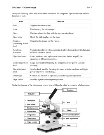
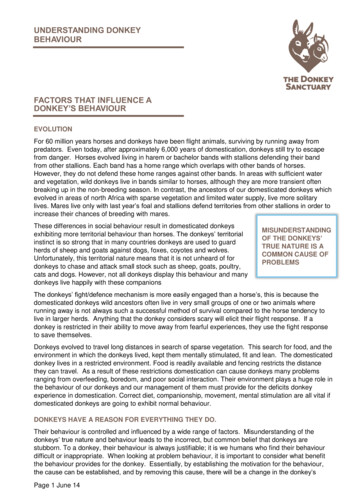
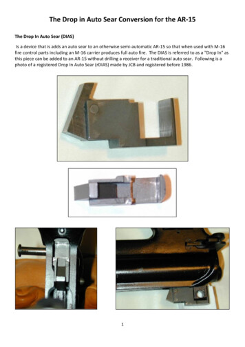
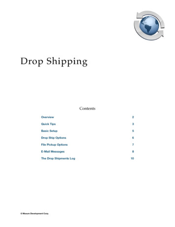
Introductionstress. Examples which use HVDC connections for transmission of electrical power fromgenerating station to power distribution station are shown below. Figure 1.1 shows the 800 kV UHVDC which is the world’s longest transmission link between Xiangjiaba andShanghai in China.Figure 1.1: 800 kV UHVDC transmission line in ChinaFigure 1.2 shows the 500kV HVDC line from Mundra in Gujarat to Mohindergarh nearNew Delhi in the power deficit state of Haryana.Figure 1.2: 500kV HVDC line in IndiaFigure 1.3 shows the large scale offshore wind farm cluster in the North Sea to theGermany power grid. It helps Germany towards its target of 35 percent renewableelectricity by 2020.2
IntroductionFigure 1.3: HVDC link between offshore wind farms to Germany gridPollution behavior of insulators under HVDC stress is different from HVAC stressbecause of large contamination due to electrostatic forces and long duration of partialarcs. It is very important to know this behavior because the flashover of pollutedinsulators can cause power outage of long duration over a large area. Pollution flashoveris playing an important role in the design of transmission lines and converting stations,especially used in DC system.There is still so much research work to be done on the polluted insulators to know thebehavior of them under HVDC stress. There are many issues to discuss about pollutedinsulators. There are also some cases where insulator structures are in parallel. Thiscan be on transmission lines or in substation equipment. Some examples which showparallel insulator structures are displayed in figures 1.4-1.7.3
IntroductionFigure 1.4: Parallel insulators used in transmission lineFigure 1.5: Vertical break disconnector4
IntroductionFigure 1.6: Pantograph disconnectorsFigure 1.7: Knee type disconnectorsNo research on the insulators when they are in parallel under HVDC has been done.This is one of the issues discussed in this report. This dissertation concentrates mainlyon two issues. One is the behavior of a water drop on the insulator surface under DCstress, and the other issue is the behavior of parallel insulators under DC stress.Simulation work has been done on those two problems. The theory regarding water dropbehavior and flashover mechanism is also explained in the dissertation.1.2 Organization of WorkExtensive work has been carried out in the last few decades to know the behavior ofpolluted insulators under AC stress. There are only few literature sources availablewhich tried to explain the behavior of polluted insulators under DC stress. Also there aresome literatures available to explain the behavior of water drops on the insulator surfaceunder AC stress. However, there is no description for the behavior of a water drop onthe insulator shed surface under DC stress. This dissertation explains the behavior of amoving water drop on porcelain and composite insulator sheds. It also shows the effectof a hanging water drop at the end of an insulator shed.5
IntroductionThere has been no research done on the polluted insulators when two insulators are inparallel. This dissertation shows the behavior of parallel polluted insulators under DCstress. A simple model for parallel insulators has been created and explains the electricfield between and outside of the two insulators.Introduction and the brief description of insulators and pollution environments areexplained in chapter 1 and 2. A detailed theory about the software considered for thesimulation and the important parameters considered in the software are explained inchapter 3.The characteristic of partial discharges under AC is well known. There are so manypublications about the detection and evaluation of partial discharge parameters at ACvoltage. However, there is a little knowledge about characteristics of partial discharge atDC voltage. The theory part of the partial discharges at DC voltage which is differentfrom the partial discharges at AC voltage is explained in chapter 4.In chapters 5 and 6, the behavior of a water drop under DC stress and simulation resultson a water drop placed on the porcelain and composite insulator sheds are presented.Chapter 7 demonstrates the behavior of parallel insulators with and without pollution.The difference in performance of parallel insulators when compared to a single insulatoris explained in chapter 7.1. Electric field performance on the surfaces of parallelinsulators is discussed in chapter 7.2. Then chapter 7.3 illustrates the study of theelectric field on parallel insulators with and without pollution. The critical positionbetween the parallel insulators is shown in chapter 7.4. Finally some conclusions arebriefly given in chapter 7.5.Results, discussions and recommendations for future work are illustrated in chapters 8.6
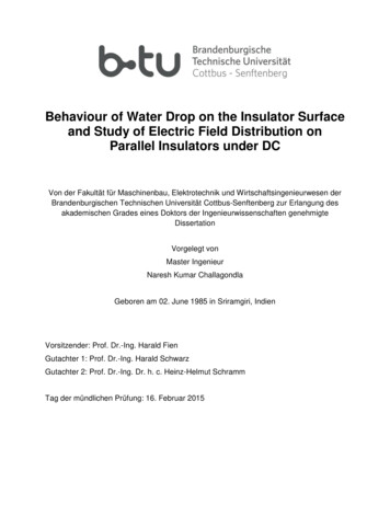
Basic Knowledge2 Basic KnowledgeThis chapter deals with the insulators and the problems encountered with them.2.1 Types of InsulatorsBased on the usage there are two types of insulators available. They are line insulatorsand post insulators. There is a clear explanation in the following chapters.2.1.1 Line InsulatorsLine insulators are used to insulate the tower or pole from the live electrical line. Theseline insulators may consist of a string of insulator units, depending on the insulator typesand application. Generally if the line voltage increases, more insulator units are used inthe string.The overhead line insulators are mostly made of the following materials1) Porcelain insulators, which are ceramic materials made by heating raw materials,generally including clay in the form of kaolin, in an oven up to temperatures between1,200 C (2,192 F ) and 1,400 C (2,552 F). Some insulators made of porcelain areshown in following figures (figures 2.1 to 2.3)Figure 2.1: 10 kV insulator7
Basic KnowledgeFigure 2.2: Porcelain insulators for power lineFigure 2.3: Porcelain insulator at railways2) Glass insulators, which are used for disc and pin types. Thermal stability of thismaterial is consistent up to 538 C. Insulator made of glass is shown in figure 2.48
Basic KnowledgeFigure 2.4: Suspended glass disk insulator unit used in cap and pin insulator strings for highvoltage transmission lines3) Composite polymer insulators, which may be a combination of fiberglass, plastic andresin. These are sometimes used for the long rod and post type insulators and havebeen in service for more than 25 years. A modern composite insulator core consists ofglass fibers in a resin based matrix to achieve maximum tensile strength.Figure 2.5: Synthetic composite insulatorTo strengthen the structure of insulator, we use a FRP rod (fiber reinforced polymer).The housing in figure 2.5 that encloses silicon rubber also forms the weather sheds andmay be hydrophobic (water repellent), which helps to reduce leakage current. Somehousings are designed to remain hydrophobic when polluted, giving composite9
Basic Knowledgesynthetics a distinct advantage over porcelain types. Some composite insulators whichare used for distribution overhead power lines and transmission overhead power linesare shown in figure 2.6.Figure 2.6: Long rod insulators for distribution and transmission overhead power lines4) Plasticized wood insulators also referred to as polymer concrete has been used formedium voltage line insulators. These are shown in figure 2.7. Although uncommon,there are a number of insulator styles made from wood. The best known and mostdesirable wood insulators are made from the dense wood lignum vitae for the SanFrancisco trolley system. Since these designs utilize organic material, there have beenconcerns about material life span [FRE 2000].Figure 2.7: Insulators made up of wood10
Basic Knowledge2.1.2 Post InsulatorsMost of the post insulators are used in electrical substations and they are manufacturedfrom porcelain or composite insulating materials. Post insulators have metal bolts whichare made of aluminum alloy. These are called flanges. Mainly post insulators are used insubstations to insulate high voltage switchgear and transformers. Some examples ofpost insulators are shown in figures 2.8 and 2.9.Figure 2.8: Post insulators made of porcelain11
Basic KnowledgeFigure 2.9: Post insulator made of composite materials2.2 Classes of PollutionAccording to IEC standards [IEC 2008], there are two main basic types of insulatorpollution which may lead to flashover. Those two types are type A and type B which areexplained below.Type A (Solid Pollution)Solid pollution with non-soluble components deposited on the insulator surface. A wetconducting path is formed when moisture is present due to dew deposition or light rainand leakage current begins to flow on the insulator surface. This type of pollution can becharacterized by ESDD/NSDD (equivalent salt deposit density/ non soluble depositdensity) and DDGIS/DDGIN (dust deposit gauge index soluble/ dust deposit gaugeindex non soluble). The ESDD of a solid pollution layer may also be evaluated bysurface conductivity under controlled wetting conditions.Type A pollution is most often associated with inland, desert or industrially pollutedareas. It can also arise in coastal areas in cases where a dry salt layer builds and thenrapidly becomes wetted by dew, mist, fog or drizzle.Type A pollution has two main components, namely soluble pollution that forms aconductive layer when wetted, and non-soluble pollution that forms a binding layer forsoluble pollution. These are described in the following paragraph.12
Basic KnowledgeSoluble pollution is subdivided into high solubility salts (e.g. salts which dissolve readilyinto water) and low solubility salts (e.g. hardly soluble salts). Soluble pollution ismeasured in terms of equivalent salt deposit density (ESDD) in mg/cm 2. Examples ofnon soluble pollutions are dust, sand, clay, oil, etc. Non soluble pollution is measured interms of non-soluble deposit density (NSDD) in mg/cm2.Type B (Liquid Pollution)Liquid electrolytes deposited on the insulator with very little or no non-solublecomponents. This type of pollution can be best characterized by conductance or leakagecurrent measurements.Type B pollution is most often associated with coastal areas where salt water orconductive fog is deposited onto the insulator surface. Other sources of type B pollutionsare crop spraying, chemical mists and acid rain.2.3 Types of EnvironmentsEnvironments are described by the following five types. These types are describing thetypical pollution characteristics for a region. Examples of the type of pollution (A or B) fora particular environment are explained below. In practice most polluted environmentscomprise more than one of these types, for example coastal regions with sandybeaches. In these cases it is important to determine which pollution type (A or B) isdominant.Desert type environmentsThese are areas which are characterized by sandy soils with extended periods of dryconditions. The pollution layer in these areas normally comprises salts that dissolveslowly in combination with a high NSDD level (type A). The insulators are pollutedmainly by wind borne pollution. Natural cleaning can occur under the infrequent periodsof rain or by “sand blasting” during strong wind conditions. Infrequent rain combined withthe slow dissolving salts causes natural cleaning to be less effective. Critical wetting,13
Basic Knowledgewhich poses a risk for insulator flashover, can occur frequently in the form of dew on theinsulators.In recent publications, there have been reports of contamination levels as much as 1.4𝑚𝑔/𝑐𝑚2 at measuring sites in desert places [INM 2014]. Such contamination levels fallbeyond the typical ranges considered in the relevant international standard [IEC 2008].Application of ceramic insulators with the specific creepage distance provided in recentstandards (i.e. 31 mm/kV phase-to-phase voltage or 53.7 mm/kV phase-to-ground) hasproven insufficient in many of these problematic service areas.Coastal type environmentsThese areas are typically in the direct vicinity of the coast, but in some cases, dependingon topography, they can be as far as 50 km inland. Pollution is deposited onto theinsulators mainly by spray, wind and fog. The pollution build-up is generally rapid,especially during spray or conductive fog conditions (type B). A build-up of pollution overa longer term can also occur through a deposit of wind-borne particles, where thepollution layer on the insulators consists of quick dissolving salts with a degree of inertcomponent (type A) which depends on the local ground characteristics. Natural cleaningof the insulators is typically effective as the active pollution consists mainly of fastdissolving saltsIndustrial type environmentsThese are areas located in close proximity to an industrial pollution source, and mayeffect only few installations. The pollution layer may constitute conductive particulatepollution, such as coal, metallic deposits; or dissolved gasses, such as NOx, SOx (typeB); or pollution that dissolves slowly, such as cement, gypsum (type A). The pollutionlayer may have a medium to high inert component (medium to high NSDD) (type A). Theeffectiveness of natural cleaning in industrial areas can vary greatly depending on thetype of pollution present. The pollution often consists of heavy particles which settle onhorizontal surfaces.14
Basic KnowledgeAgriculture type environmentsThese are areas which are situated in the vicinity of agricultural activity. Typically therewill be areas subjected to ploughing (type A) or crop spraying (type B). The pollutionlayer on the insulators consists mostly of fast or slowly dissolving salts such aschemicals, bird droppings or salts presen
The dissertation explains the behavior of a water drop on insulator shed surface energized with DC. It deals with the moving water drop and hanging drop at the edge of . under service voltage are caused by adverse environmental conditions, as some pollution layer is deposited on the insulator surface. A wet conducting path is formed due