Transcription
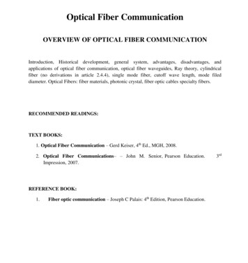
Fiber in Data CentersWhat’s Next?Srinivasan B, RCDD
Hubbell Fiber Systems10G / 40G / 100G / 400GStandards, Applications andPractices
Agenda Part 1: Current Technologies Standards Review IEEE 802.3: Ethernet Fundamentals TIA-568.3-D: Telecommunications Fiber Cabling TIA-942-A: Data Center Standard Overview IEEE 802.3ba: Fiber 40G and 100G Channel Overview Migration: 10G - 40G - 100G - 400G IEEE 802.3bs: 400G Draft Standard Singlemode 40G/100G Summary: Evolution and Migration Strategy
Agenda Part 2: New Developments, 2017 IEEE 802.3by: Introduction of 25Gb/s IEEE 802.3bm: Application of 25Gb/s to 40G and 100G Protocols IEEE 802.3bm: New 40G Singlemode Application Impact of 25Gb/s on Future Migration: 40G/100G/400G Emergence of Wide Band OM5 Multimode OM5 applications and impact on 100G/400G migration Maintaining MPO 12-Fiber Infrastructure Conclusion
Local Area and Metro Networking StandardsIEEE 802.3Networking Standards:Basic Overview
IEEE 802.3 Ethernet StandardIEEE 802.3: Carrier Sense Multiple Access with Collision Detection(CSMA/CD) IEEE 802.3 is a “Living Document” defining the Physical Layer and Data LinkLayer Ethernet specifications for Local Area and Metro Networks. CSMA/CD is the “traffic control” technology for network access and signaling. New Technologies are continually published on 802.3 addenda. Current Multimode short wave Ethernet protocols: 1 Gb/s: 1000BASE-SX (1 fiber pair) 10 Gb/s: 10GBASE-S (1 fiber pair) 25 Gb/s: 25GBASE-S (1 fiber pair) 40 Gb/s: 40GBASE-SR4 (4 X 10G pairs 8 Fibers) 100 Gigabit Ethernet: 100GBASE-SR10 (10 X 10G pairs 20 Fibers)
IEEE 802.3 Ethernet StandardBasic Elements of Ethernet Message Transfer Devices on a network have a MAC and IP address Ethernet frames travel between MAC devices through network cabling,switches, and routers Frame “collisions” at a node are detected and sequenced Collision Detection is the fundamental concept of EthernetBasic Network Elements Defined LAN: Switch-based network, single broadcast domain in a building WAN: Router-based network, multiple broadcast domains SAN: Switch-based network, storage equipment domains MAC: Medium Access Control (protocol for access network devices) IP Address: Internet protocol (for internet access to network devices)
IEEE 802.3 Ethernet StandardLAN-WAN-SAN Campus Network ExampleWANRouterBuilding #1Building #2
IEEE 802.3 Ethernet StandardContents of an Ethernet Medium Access Control (MAC) frameStart of Destination SourcePreamble FrameAddressAddressDelimiterPacket Errors affectnetwork e
Impact of Cabling on Data RateTransport Layer and Quality of Data Transfer Impacted by cabling, components, and installation Primary cause of Optical Bit Errors: Insertion loss, modal dispersion, and back reflections Impact of Bit Errors Corruption of data packets Packet rejection by the Transport Layer (Delay) Result: Slow network speeds High Bit Error Rate DELAY
TIA-568.3 Standard: Key DevelopmentsCurrent Revision: TIA-568.3-D (December, 2015) Replaces TIA-568-C.3 Incorporates 24-fiber MPO connector Two rows of 12 fibers Supports 100GBASE-SR10 Defines MPO Polarities for 10G, 40G, and 100G A Polarity: Straight-through, 1-1 mapping B Polarity: Reversed sequence, 1-12 mapping C Polarity: Crossed pairs, 1-2, 2-1 mapping12-Fiber MPO24-Fiber MPO
TIA-568.3 Standard: Key SpecificationsConnector Mated Pair: Insertion Loss 0.75 dB Maximum (Note: 0.5 dB is typically recognized)Connector Mated Pair: Minimum Return Loss OM3 and OM4: 20 dB Singlemode UPC: 35 dB Singlemode APC: 55 dBOM3 and OM4 Multimode Cable Loss 3.0 dB/km @ 850 nm 1.5 dB/km @ 1300 nmOS2 Singlemode Cable Loss @ 1310, 1383, and 1550 nm Indoor: 1.0 dB/km Indoor/Outdoor: 0.5 dB/km Outside Plant: 0.4 dB/km
TIA-568.3: 10G MPO Infrastructure10GBASE-S MPO Cabling: 4-Connector Channel OM3 Channel Limits: 300 meters, 2.6 dB Max OM4 Channel Limits: 550 meters, 3.1 dB MaxLC DuplexReceptacleLC DuplexReceptacleSwitchorServerLC DuplexPatch CordMPO FemaleTrunkMPO to LCCassettesSwitchorServerLC DuplexPatch Cord
TIA-568.3: 10G Polarity ManagementRules for 10G Channel Polarity Must have one overall pair crossing, end to end In general: Must have an odd number of pair crossings, end to end Pair Crossings are managed in the patch cords, cassettes, or MPO trunkSwitchorServerLC Duplex CordReversed PolarityMPO FemaleTrunkMPO to LCCassettesSwitchorServerLC Duplex CordStraight Polarity
Multimode Fiber EvolutionVCSEL Laser Optimized Multimode Fiber: OM3 and OM4 VCSEL Vertical Cavity Surface Emitting Laser Longer distances / Higher bandwidth at 850 nmOM3 Laser-Based Multimode Distances 1Gb/s: Up to 1,000 meters 10Gb/s: Up to 300 meters 40G/100G: Up to 100 metersOM4 Laser-Based Multimode Distances 1Gb/s: Up to 1,100 meters 10Gb/s: Up to 550 meters 40G/100G: Up to 150 meters
IEEE 802.3 Physical Layer Data Link10 GbE Fiber Transceivers are Laser Based Transmitter: Converts digital to optical by laser modulation Receiver: Converts optical to digital by photo detectionTXDigitalInputVCSEL Laser850 ctorOPTXVCSEL Laser850nmFiber 10/25 Gb/s Physical Layer Data LinkDigitalInput
Multimode Fiber EvolutionBend Insensitive Laser Optimized OM3 and OM4 New bend radius performance introduced by ITU, TIA, and IEC standards Modified cladding index band around core New cladding chemical formulation Performance Advantages: Longer cable fatigue life under bend loading Lower dB loss at a smaller bend radius50 Micron CoreGraded IndexCladding125 MicronTight BendRadius:5 to10 mmModified RefractiveIndex Band AroundCoreMultimode FiberCross Section
Singlemode Fiber EvolutionBend Insensitive Singlemode Fiber: OS2 Grade OS2 singlemode replaces legacy OS1 OS2 improvements similar to multimode: Modified cladding refractive index band around core New cladding chemical formulation Improved fatigue life and lower dB bend loss9 Micron Core,Step IndexTight BendRadius:5 to10 mmCladding125 MicronModified RefractiveIndex Band AroundCoreSinglemode FiberCross Section
Data Center: TIA-942 UpdateTIA-942-A: Telecommunications Infrastructure Standard for DataCenters Replaces TIA/EIA-942 Incorporates two addenda: AD1: Coaxial cable (T-3, E-1 and E-3) and distances AD2: Energy efficiency: wider range of temp and humidity, 3-level lighting,Cat 6A, noise sources, updated tier structure Terminology: Harmonized with 568-C series and ISO/IEC Added references to TIA-569-C, TIA-606-A and TIA-607 New Infrastructure elements added for large data centers: IDA - Intermediate Distribution Area ICC - Intermediate Cross Connect
Data Center: TIA-942 TopologiesKey Elements of the Data Center using Fiber Cabling Equipment Distribution Area (EDA) Main Distribution Area (MDA)Data AMC, Router, Switch, rversAP
Data Center OverviewWhat is a Data Center?A large group of networked computer servers used for remotestorage, processing, and distribution of large volumes of data.
Data Center OverviewANSI/BICSI 002-2014: Data Center Design and Best Practices BICSI is a publication of general guidelines
Data Center: ANSI/BICSI 002-2014Key Topics Covered by ANSI/BICSI 002-2014 Site Selection Space Planning Architectural Structural Electrical Systems Mechanical Fire Protection Management and Building Automation Systems Cabling Infrastructure, Pathways and Spaces Security and Disaster Recovery Commissioning Data Center Maintenance
Fiber Data Center ApplicationsFundamental Cabling Topologies Server Fabric / SAN Fabric Switch/SAN to Servers Servers to MDA/LANBasic Fiber Infrastructure Equipment and Patch Cords Local Interconnect Units (LIU’s) Interconnect MPO Trunk Cords
Data Center: Key Fiber Products Interconnect Enclosures Pre-Terminated MPO cassettes MPO Trunk assemblies LC duplex patch cords
What is an MTP (MPO) Connector?“MTP” or “MPO” is a 12 or 24 Fiber Array Connector MTP* Multi Fiber Termination Push-on MPO Multi Fiber Pull OffKey Characteristics Rectangular ferrule with fibers equally spacedKeyed connector body for orientationPrecision flat polish end faceMale connectors have two alignment TP is a registered trademark of US Connec
MPO 12-Fiber Connector PolarityType ‘A’ Polarity: Straight-Through, No pair crossing Most universal termination Pin 1 to Pin 1 direct mapping, end to endAdvantages 10G pair crossing managed externally in the patch cords Compatible with 10G or 40G applicationsMPO Near End: Key Up1234567891011MPO Far End: Key Up12123456789101112
MPO 12-Fiber Connector PolarityType ‘B’ Polarity: Reversed Sequence Key-wise reversal: Pin 1 to Pin 12 mappingAdvantages Provides 40G-ready B-polarity flip in the MPO trunk Sequential reversal provides individual pair crossingMPO Near End: Key Up1234567891011MPO Far End: Key Up12121110987654321
MPO 12-Fiber Connector PolarityType ‘C’ Polarity: Crossed pairs All pairs crossed end to end Pin 1 to Pin 2 / Pin 2 to Pin 1 mapping Not compatible with 40G migrationAdvantages 10G channel pair crossings are managed in the trunk Can use standard polarity patch cords (no reversing)MPO Far End: Key UpMPO Near End: Key Up123456789101112214365871091211
New Developments in MPO Technology24-Fiber MPO Connector Two rows of 12 fibers in the same MPO footprint Supports 100GBASE-SR10 Supports 10G and 40G channel consolidationMPO Near End: Key UpReceive fibers across top rowTransmit fibers across bottom row4 outer fibers not used
MPO 10G Fiber Interconnect TrunksManufactured in 12-Fiber Multiples A, B, or C polarities are user-defined12-Strand MPO on each end (no pins) Cassettes have pinned male MPO receptacles MPO transceivers are also pinned male24-Strand48-Strand
MPO Transition AssembliesTransition from MPO to LC Connector Fan-Out Known as a “Hydra” assembly MPO 12-strand to (6) LC X 10G pairs Used for LC backbone channel consolidation Also used for 40G 8-fiber to 10G pair break-out MPO Reduces Tx/Rx congestion at the equipment
40G and 100G OverviewIEEE 802.3ba:40G and 100G Ethernet(Original Standard Release)
IEEE 802.3ba: 40 Gb/s Overview40GBASE-SR4: Ratified Addendum IEEE 802.3ba, 2008 Optics: 850 nm over 8 multimode fibers (4 pairs / 4 lanes) Transceivers: MPO male, 12-fiber interface 40G Multimode distance Limits: OM3: 100 meters OM4: 150 meters Strictly MPO cabling channel, end to end(4) Un-used middle fibersNOTE: 1 Lane 1 Pair40GBASE-SR4 MPO TransceiverLane Assignments
IEEE802.3ba: 40 Gb/s Overview40 GbE Fiber Cabling Channel and dB Attenuation Limits OM3: 1.9 dB maxOM4: 1.5 dB maxIEEE suggests a maximum 2-connector channel (shown below)NOTE: Beyond 2 mated pairs may exceed dB insertion loss limitsNo migration from legacy LC/SC cabling4 Pairs4 Pairs40GbE: 4 Pair, 2-Connector MPO Channel4 Pairs
IEEE 802.3ba: 40 Gb/s OverviewWhy use an MPO/MTP connector interface? Maximum fiber density in a small foot print MPO/MTP connectors are well recognized Equal fiber lengths minimize delay skewPolished fibers,equal in length40GBASE-SR4 Lane Assignments
40Gb/s Overview: Channel Polarity RuleThere must be one Type ‘B’ (key-wise) polarity reversal end to end In general: Must have an odd number of key-wise polarity reversals end to endManaging 40G Channel ‘B’ Polarity Reversal In the MPO patch cord - either endIn the MPO trunkOr - Use a polarity-reversed MPO adapter panel in LIU #1 or LIU #2Polarity-reversed MPO adapters are available, with a gray colorLIU #1LIU #2MPO 12-Fiber TrunkFMPO Patch CordMMMPO PanelsFMPO Patch Cord
IEEE 802.3ba: 40Gb/s SummaryNative 40G is a Pre-Terminated 8-Fiber MPO Channel, End to End Supported by legacy 10G 12-fiber MPO cabling Positioned for new applications (see “New Developments”)40G Cabling Design and Implementation Adhere to a 2-connector channel, distance, and dB loss limits Use a consistent channel polarity scheme, end to end Consider 40G/100G migration strategy
IEEE802.3ba: 100 GbE Overview100GBASE-SR10: Established in addendum IEEE 802.3ba, 2008 Optics: 850 nm over 20 fibers in parallel (10 pairs / 10 lanes) Transceivers: 24-fiber MPO male (Departure from 12-fiber MPO) 100G Multimode channel distance limits: OM3: 100 meters OM4: 150 meters Strictly an MPO channel, end to end100GBASE-SR10 TransceiverLane Assignments(4) Un-used outer fibers24-Fiber MPO Connector
IEEE802.3ba: 100 GbE Overview100 GbE Fiber Cabling Channel dB Attenuation Limits OM3 Channel: 1.9 dB max OM4 Channel: 1.5 dB max IEEE suggests a maximum 2-connector channel (shown below) NOTE: Beyond 2 mated pairs may exceed dB insertion loss limits No migration from legacy LC/SC cabling10 Pairs10 Pairs100GbE: 10-Pair, 2-Connector MPO Channel10 Pairs
100Gb/s Overview: Channel Polarity RuleThere must be one Type ‘B’ (key-wise) polarity reversal end to end In general: Must have an odd number of key-wise polarity reversals end to end 100G polarity is similar to the 40G polarity ruleManaging 100G Channel ‘B’ Polarity Reversal In the MPO patch cord - either endIn the MPO trunkUse a polarity-reversed MPO adapter panel in LIU #1 or LIU #2In the consolidation module if migrating legacy 12-fiber MPO cabling **LIU #1FMPO Patch CordMPO 12-Fiber TrunkMLIU #2MMPO PanelsFMPO Patch Cord** Not Recommended
40G/100G Overview: Notes on GenderAll MPO Junctions are Male to Female Male MPO connectors have alignment pins MPO adapters only facilitate pre-alignmentGeneral Guidelines for Native 40G/100G Cabling Transceiver receptacles are always pinned MPO maleMPO patch cords should be female, both endsMPO trunks should be pinned male both ends to create a receptacleIn general, the “permanent” side of any MPO receptacle should be pinned maleLIU #1FFLIU #2MMFFMPO TrunkMPO Patch CordMPO PanelsMPO Patch Cord** Not Recommended
IEEE 802.3ba: 100GbE Summary802.3ba 100G is an Independent 24-fiber MPO Channel, End to End Direct equipment interconnect only, “chip to chip” Supported by legacy 24-fiber MPO cabling only (see “Migration Strategies”)100G Cabling Design and Implementation Adhere to a 2-connector channel, distance and dB loss limitsConsolidation of legacy 12-fiber MPO infrastructure is not recommended **Add 100G 24-fiber MPO channels separately to simplify administrationConsider a 100G – 400G migration strategy (see “New Developments”)** 4-connector channel dB loss violation
40G/100G: Worst Case 100m Channel LossFor a 2-Connector MPO Channel (2 LIU’s), per TIA-568.3 Loss Spec of 0.75 dB: Total Mated Pair Insertion Loss 0.75 X 2 1.50 dB (Worst Case) Add 0.3 dB for 100 meter channel length: Total channel loss 1.80 dB OM3 Channel dB Loss Limit 1.90 dB @ 100 m OM4 Channel dB Loss Limit 1.50 dB @ 150 m The worst case 2-connector channel loss is marginal Reducing the mated pair loss specification to 0.5 dB becomes necessaryLIU #1FMPO Patch CordMPO 12-Fiber TrunkMLIU #2MMPO Panels(2 Mated Pairs)FMPO Patch Cord
40G/100G: “Typical” 100m Channel LossFor a 2-Connector MPO Channel (2 LIU’s), Using a Loss Spec of 0.50 dB: Total Mated Pair Insertion Loss 0.50 X 2 1.00 dB Add 0.3 dB for 100 meter channel length: Total channel loss 1.30 dB OM3 Channel dB Loss Limit 1.90 dB @ 100 m OM4 Channel dB Loss Limit 1.50 dB @ 150 m The 2-connector channel loss is robust at 0.50 dB per mated pair Adding one mated pair junction at 0.50 dB in the channel becomes marginalLIU #1FMPO 12-Fiber TrunkMLIU #2MFMPO Panels(2 Mated Pairs)MPO Patch CordMPO Patch Cord
40G/100G: Low Loss MPO Connections4-Connector, 100m MPO Channel (4 LIU’s), Using 0.35 dB Specification Total Mated Pair Insertion Loss 0.35 dB X 4 1.50 dB Add 0.3 dB for 100 meter channel length: Total channel loss 1.80 dB OM3 Channel dB Loss Limit 1.90 dB OM4 Channel dB Loss Limit 1.50 dB The 4-Connector channel is marginal with low loss MPO connectorsLIU #1FMLIU #2FMLIU #3FFLIU #4MFMMPO TrunkMPO Patch Cord0.35 dBLow LossMPO “Elite”MPO Patch CordF
Summary: Low Loss MPO ConnectorsLow loss connectivity is required for a 4-connector MPO channel (4) Low loss MPO junctions increases cost, administration, and points of failure Low loss MPO connectors will permit a robust 3-connector channel A 3-connector channel permits one consolidation or polarity-changing module Best design is a 2-connector channel with standard loss connectorsLIU #1FMMPO Patch CordLIU #2FMLIU #3FMPO TrunkMPO “Elite”JunctionsFLIU #4MFMMPO Patch CordF
10G to 40G Migration MethodsMethod 1: De-Commissioning Legacy 10G MPO Cabling Requires substantial elimination of existing cabling infrastructure Scrap everything end to end, except the MPO trunkLC DuplexReceptacles10GSwitchorServerLC DuplexPatch CordsLC DuplexReceptaclesMPO 10GFemale TrunkMPO to LCCassettes10GSwitchorServerLC DuplexPatch Cords
10G to 40G Migration: Method 1After Elimination of LC Cords and MPO Cassettes, Both Ends Add: MPO feed-through panels and MPO 40G patch cords (Note Gender) NOTE 40G Polarity Rule: One Type ‘B’ reversal, end to end40G MPO MaleTx/Rx ReceptacleExisting MPOFemale Trunk40GTx/RxFMPO 40G Femaleto Male Patch CordB-Polarity40G MPO MaleTx/Rx ReceptacleM40GTx/RxMMPO Feed-ThroughAdapter PanelFMPO 40G Femaleto Male Patch CordA-Polarity
10G to 40G Migration: Method 2 - NativeMethod 2: Add 40G Channels Separately: No De-Commissioning 10G Add: MPO trunk, MPO panels and MPO 40G patch cords (Note Gender) 40G Polarity Rule: One Type ‘B’ reversal, end to end40G MPO MaleTx/Rx Receptacle40GTx/Rx40GTx/RxNew 40G MPO TrunkFMPO 40G FemalePatch CordB-Polarity40G MPO MaleTx/Rx ReceptacleFMMPO Feed-ThroughAdapter PanelMFFMPO 40G FemalePatch CordA-Polarity
40G to 100G Migration: Method 1Method 1: De-Commissioning Existing 40G 12-Fiber Cabling Replace: 40G MPO patch cords with 100G MPO patch cords, both ends Replace: MPO adapter panels with consolidation modules (Note Gender) Consolidate: 40G 12-strand MPO trunks: 2 into 1 (Note: only 12-strand will work)100G MPO MaleTx/Rx ReceptacleConsolidatedMPO Trunks100GTx/RxFMPO 100G FemalePatch Cord24-Strand100G MPO MaleTx/Rx ReceptacleF100GTx/RxFMPO 2 into 1ConsolidationModulesFMPO 100G FemalePatch Cord 24Strand
40G to 100G MigrationWhat is a 100G MPO “Consolidation Module” ? A CM combines two 12-fiber MPO inputs into one 24-fiber MPO output Also known as a “2 into 1 conversion cassette” CM’s are also used to “re-map” polarities into 100G format. NOTE: A CM creates a 4-connector MPO channel – Not RecommendedMPO 100G MaleReceptacle24-Fiber Output2 x 12-FiberMPO CordsCMMPO 100G FemalePatch Cord24-FiberMPO 100G MaleReceptacle24-Fiber OutputCMMPO 12-Fiber MaleReceptacle InputsMPO 100G FemalePatch Cord24-Fiber
40G to 100G Migration: Method 2 - NativeMethod 2: Add 100G Channels Separately: No De-Commissioning 40G Add: MPO male trunk, MPO panels, and MPO 100G patch cords (Note Gender) 100G Polarity Rule: One Type ‘B’ reversal, end to end100G MPO MaleTx/Rx Receptacle100GTx/Rx100GTx/RxNew 100G MPO TrunkFMPO 100G FemalePatch CordB-Polarity100G MPO MaleTx/Rx ReceptacleFMMPO Feed-ThroughAdapter PanelMFFMPO 100G FemalePatch CordA-Polarity
40G to 100G Migration: SummaryNotes Regarding Migration to 100 GbE A 2-Connector channel is recommended due to channel loss budgets Consolidation Modules create a 4-connector channel – Not Recommended 100G cabling should be a native new installation, using OM4 fiber See “New Developments” for further evolution of this technology100G MPO MaleTx/Rx Receptacle100GTx/Rx100GTx/RxNew 100G MPO TrunkFMPO 100G FemalePatch Cord100G MPO MaleTx/Rx ReceptacleFMMPO Feed-ThroughAdapter PanelsMFFMPO 100G FemalePatch Cord
IEEE 802.3ba: Singlemode 40 Gb/s40GBASE-LR4: Long Range Singlemode 40 Gb/s Optics: (4) WDM 10G wavelengths over a single lane (1 or 2 fibers) Transceivers: LC Duplex Utilizes conventional simplex or duplex cabling channel 40GBASE-LR4 Max operating distance: 10 km
IEEE 802.3ba: Singlemode 40 Gb/s40GBASE-ER4: Extended Range Singlemode 40 Gb/s Optics: (4) WDM 10G wavelengths over a single lane (1 or 2 fibers) Transceivers: LC Duplex Utilizes conventional simplex or duplex cabling channel 40GBASE-ER4 Max operating distance: 30 km
IEEE 802.3ba: Singlemode 40 Gb/s CablingIEEE 802.3ba: Singlemode 40G Cabling Model Simplex or duplex fiber channel Can migrate from legacy singlemode fiber plant IEEE 802.3ba power budgets apply Transceivers utilize conventional LC duplex40GBASE-LR4/ER4 Singlemode Cabling Model
IEEE 802.3ba: Singlemode 100 Gb/s100GBASE-LR4 and 100GBASE-ER4 Optics: (4) WDM 25G wavelengths over a single lane (1 or 2 fibers) Transceiver Interface: LC Duplex Max operating distance for 100GBASE-LR4: 10 km Max operating distance for 100GBASE-ER4: 30 km
IEEE 802.3ba: Singlemode 100 Gb/s CablingIEEE 802.3ba: Singlemode 100 Gb/s Cabling Model Full duplex transmission over a single or duplex fiber Same cabling model as 40GBASE-LR4/ER4 Can migrate from legacy cabling plant Standard LC Transceiver interface100GBASE-LR4/ER4 Singlemode Cabling Model
Fiber 40/100 Gb/s Singlemode SummaryMigration of Singlemode Cabling from 10 GbE to 40/100 Gb/s Legacy singlemode cabling can migrate from 10 Gb/s to 40/100 Gb/s Transceivers have a conventional LC duplex interface Cabling test parameters of IEEE 802.3ba apply Full Duplex over a single fiber Full Duplex over a pair of fibers See “New Developments” for Singlemode Advancements
IEEE 802.3bs: 400G Baseline (2018)400GBASE-SR16 Lane Assignments Defined as (4) 100GBASE-SR4 Channels Total 32-fiber channel: 16 X 25G pairs Employs a new 32-fiber MPO connector – Two rows of 16 fibers Direct-connect or 2-connector MPO channel only Departure from standard MPO interface: Key shift off-centerWill this be adopted?See “New Developments”32-Fiber MPOConnector
IEEE 802.3bs: Timeline for 400 Gb/sPublished Standard Anticipated in Q4, 2017 400GBASE-SR16 for OM3/OM4 multimode PSM4 Singlemode: 4 x 100G singlemode lanes NOTE: New Developments may impact adoption of 400GBASE-SR16 !!!
Part 2: New Developments, 2017 Update IEEE 802.3by: Introduction of 25Gb/s IEEE 802.3bm: Application of 25Gb/s to 40G and 100G Protocols Impact of 25Gb/s on “Legacy” Migration: 40G/100G/400G Non-IEEE 40G Singlemode Applications Emergence of Wide Band OM5 Multimode (WBMMF) IEEE 802.3cd Task Force – Future Applications Maintaining MPO 12-Fiber Infrastructure Conclusion
Introduction of 25 Gb/s: IEEE 802.3byIEEE 802.3by: Introduction of 25GBASE-SR, June, 2016 Basic Objectives: Increase 1-lane throughput from 10 Gb/s to 25 Gb/sReduce energy consumptionPreserve Ethernet protocolsSupport IEEE 802.3bm objectivesEstablish a cost-optimized path to 100GBASE-SR4 Optics: 850 nm / 25 Gb/s full duplex over 2 fibers (1 lane) Transceivers: LC Duplex 25GBASE-SR Multimode channel distance limits: OM4: 100 meters OM3: 70 meters
New 100 Gb/s Standard: IEEE 802.3bmIEEE 802.3bm: Evolution to 100GBASE-SR4, March, 2015 Basic Objectives: Reduce 100GBASE-SR10 lane count from 10 to 4 lanes (20 to 8 fibers)Extend 40GBASE-ER4 to 40 kmFurther reduce energy consumptionPreserve Ethernet protocolsFacilitate migration from 40GBASE-SR4 Optics: 850 nm 100G full duplex over 8 fibers ( 4 lanes) Transceivers: MPO 12-Fiber (multimode) 100GBASE-SR4: New multimode channel distance limits: OM4: 100 meters OM3: 70 meters
Impact of IEEE 802.3bm on 100G MigrationLanes Reduced to 12-Fiber MPO Channel Enables 40G and 100G operation over legacy 12-fiber MPO channel Supersedes “Legacy” 100GBASE-SR10 Eliminates 24-fiber MPO connectors for 100G Migration simplified to MPO polarity and gender management40GOr100GTx/RxMPO 12 FiberPatch CordB-PolarityMPO MaleReceptacleMPO MaleReceptacle12 Fiber MPO TrunkFFMMPO Feed-ThroughAdapter PanelMFF40GOr100GTx/RxMPO 12-FiberPatch CordA-Polarity
IEEE 802.3bm: Singlemode 40 Gb/s40GBASE-ER4: Extended Range Singlemode 40 Gb/s Objective: Extend 40GBASE-ER4 from 30 km to 40 km Optics: 4 x 25G WDM wavelengths over 2 fibers (1 lane), full duplex Transceivers: LC Duplex New singlemode channel distance: 40 km
Non-IEEE Singlemode 100 Gb/s Apps100GBASE-PSM4: Parallel Singlemode 4-Lane Objectives: Longer 100G reach, reduce cable cost and congestion Optics: 4 x 25G lanes (8 fibers), 1310 nm full duplex Supported Transceivers: MPO 12-fiber APC Channel Distance: 500 m Application: Data Center interconnect1 2 3 44 3 2 1100G PSM4 Lane Assignments
Non-IEEE Singlemode 100 Gb/s Apps100G-CWDM4 MSA: Coarse Wavelength Division Multiplexing Objectives: Longer 100G reach, reduce cable cost and congestion Multi-Source Agreement (MSA): Compatibility across vendors Optics: 4 x 25G CWDM lanes over 2 fibers (1 lane) Supported Transceivers: LC Duplex Channel Distance: 2 km Application: Extended Data Center interconnect
Non-IEEE Singlemode 100 Gb/s Apps100G-CWDM4 OCP: Coarse Wavelength Division Multiplexing Objectives: Lower cable cost, extended 100G reach, reduced congestion Open Compute Platform (OCP): Compatibility across vendors Optics: 4 x 25G CWDM lanes over 2 fibers (1 lane) Supported Transceivers: LC Duplex Channel Distance: 500 m Application: Data Center interconnect
Emergence of Wide Band Multimode FiberWBMMF: Ratified by the Telecommunications Industry Association TIA-492-AAAE: Published in June, 2016 Supports low cost wavelengths from 850 nm to 950 nm range Application: Multiplexing 4 x CWDM short wavelengths Backward compatible with OM3 and OM4 multimode Official ISO/IEC 11801 Designation: OM5
Emergence of OM5 WBMMFFuture Objective: 100 Gb/s Through One Pair of MM FibersNon-IEEE Emerging OM5 Applications 100GBASE-SWDM4 (4 x 25G SWDM wavelengths) 200GBASE-SWDM4 (4 x 50G SWDM wavelengths) SWDM Wavelengths: 850 nm, 880 nm, 910 nm, 940 nm Full duplex over 1 WBMMF lane (2 fibers) Future Transceivers: LC Duplex, SWDM
Emergence of OM5 WBMMFAdvantages of OM5 WBMMF Using SWDM Technology Achieves maximum throughput per single MM fiber Reduces 100GBASE-SR4 lane count to 1 lane (2 fibers) Supports 100G over a single pair (4 x 25G SWDM) Enables future multiplexing schemes Longer reach than OM4 for 100GBASE-SR4 150 m vs. 100 m
Emergence of OM5 WBMMFDisadvantages of OM5 WBMMF Using SWDM TechnologyCompared to 100GBASE-SR4 over OM4 MMF: More costly than OM4 cabling (Up to 50% added cost) SWDM transceivers also 50% more costly SWDM not being considered by IEEE for next-gen MM app’s 100G SWDM cannot break out to individual 25G channels Singlemode solutions are less costly and supported by IEEE IEEE 802.3cd task force not considering OM5 or SWDM Migration from OM3/OM4 cabling not supported
IEEE 802.3cd Task Force - FutureObjectives for Future 50G/100G/200G IEEE Applications50 Gb/s: Single Lane (2 fibers) OM4 Multimode: 100 m Singlemode: 2 to 10 km100 Gb/s OM4 Multimode: 100 m, 2 lane (4 fibers) Singlemode: 500 m, 1 lane (2 fibers, consistent with IEEE 802.3 bs)200 Gb/s: 4 lane (8 fibers) OM4 Multimode: 100 m
Maintaining MPO InfrastructureContamination is the #1 Cause of Optical Network FailuresGood cleaning and inspection practices are critical Contamination will permanently damage polished fiber ends Avoid costly replacement of pre-terminated cablingAirborne AccumulationMating Dirty Connectors
Maintaining MPO InfrastructureProtecting Cable Infrastructure InvestmentTo extend the life of MPO cabling for future migration: Advanced cleaning practices are required Use recognized cleaning and inspection products RULE #1: “Clean and inspect before you connect”
Maintaining MPO InfrastructureProtecting Cable Infrastructure InvestmentAdvanced cartridge cleaning instruments are available MPO male or female – connector or ports LC connectors or ports
Maintaining MPO InfrastructureProtecting Cable Infrastructure InvestmentUse advanced inspection devices Microscope for connectors Probe for blind ports
Conclusions Migration of MPO cabling evolves with new IEEE developments Increasing data rates to reduce fiber count remains a key IEEE objective Emergence of 25 gb/s has reduced MPO fiber count and cabling costs Migration to 100GBASE-SR4 can now utilize 12-fiber MPO cabling Current 100G standards impacted by 25GBASE-SR: 100GBASE-SR10: Can be replaced by 100GBASE-SR4 400GBASE-SR16: Will this change in Draft IEEE 802.3bs?
Conclusions OM5 WBMMF may not be supported due to costly cabling and SWDM Singlemode cabling in data centers will compete with OM5 Risk with OM5: IEEE may not recognize SWDM in future standards Standards evolution continues with IEEE 802.3cd task force New 50G, 100G, 200G under development Maintenance and cleaning fiber infrastructure Increasingly important to preserve installed MPO connectivityThanks for Your Participation
Data Center: TIA-942 Update TIA-942-A: Telecommunications Infrastructure Standard for Data Centers Replaces TIA/EIA-942 Incorporates two addenda: AD1: Coaxial cable (T-3, E-1 and E-3) and distances AD2: Energy efficiency: wider range of temp and humidity, 3-level lighting, Cat 6A, noise sources, updated tier structure