Transcription
Fibre Channel CablingLive WebcastApril 19, 201810:00 AM PT
Today’s PresentersMark JonesBroadcom LimitedGreg McSorleyAmphenol CorporationZach NasonData Center Systems
Fibre Channel CablingThis webinar is for anyone with questions concerning cabling in aFibre Channel environment, specifically those who are directly orindirectly responsible for SAN cable plant design based on the16GFC and Gen 6 Fibre Channel SAN platforms.Topics discussed include:–––––FC cable plant design processCommon Cabling ComponentsCopper and Fiber Optics BreakdownReusing OpticsBit Error RatiosTopics not discussed include:––––PolarityUpper FC LayersLink Loss BudgetsEverything else
How Do I Design a Cabling Infrastructurefor a Fibre Channel Storage Area Network?
Fibre Channel SAN Cabling InfrastructureEvery cabling system is unique. This is due to variations in: The architectural structure of the building, which houses the cabling installationThe cable and connection productsThe function of the cabling installationThe types of equipment the cabling installation will support -- present and futureThe configuration of an already installed system (upgrades and retrofits)Customer requirementsManufacturer warrantiesThe design goal should be to ensure simplicity for easier management,future expansion, and serviceability.
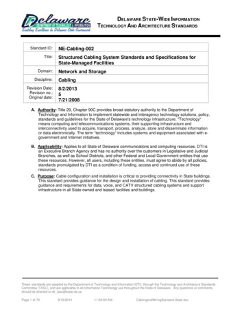
Fibre Channel SAN Network TopologiesScenario AScenario BEdge-CoreScenario CEdge-Core-EdgeScenario DFull-Mesh
Fibre Channel SAN Cabling TopologiesA physical cabling topologycan look very different than alogical network topology.
Fibre Channel SAN Cabling MethodologyFullyScalable,Manageable, andStructuredCompletelyCongested,Inconvenient, andUnstructuredEvery Data Center’s cabling infrastructure is on a spectrum between a fullyscalable, manageable and structured methodology and a completely congested,inconvenient and unstructured methodology.
What are the Common CablingComponents of Fibre Channel?
Common Components of FC CablingIntra-Data Center Links– Multi-Mode Fiber– Twinax cablesInter-Data Center andMainframe Links– Single Mode FiberFCIA webcast Long Distance FChttps://www.brighttalk.com/webcast/14967/277327
What is Structured Cabling, andWhy is it Important?
What is Structured Cabling?Structured connectivity in FibreChannel environments allows forrapid connection and cablingmanagement of switches to serversand storage and enables datacenters to plan for evolution andgrowth of IT infrastructure.Structured cabling consists of anumber of standardized smallerelements (hence structured) calledsubsystems.
We Have StandardsNetwork cabling standards are usedinternationally and are published byISO/IEC, CENELEC and theTelecommunications IndustryAssociation (TIA).In the United States, the ANSI/TIA-568-D and ANSI/TIA-942-Bstandards help to ensure a propercabling installation.
Why is Structured Cabling Necessary?With a correctly installed system your requirements of today and of tomorrow will becatered for and whatever hardware you choose to add will be supported.
Are There Copper Cablesin Fibre Channel?
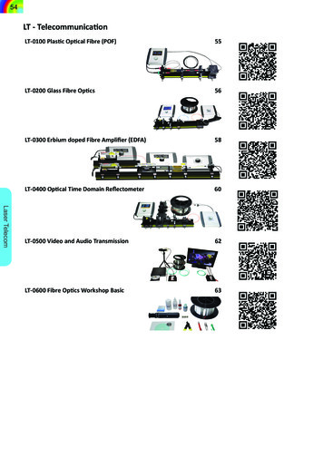
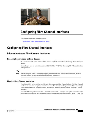
Yes. There is Copper Cables in FC.We are not talking about Twisted pairFibre Channel copper cables are Twin-Axial type of cable,transmittingTwin-Ax cable has much less insertion loss up to much higherfrequenciesinsertion loss: the ratio (expressed in dB) of incident power at one port to transmitted power at adifferent port, when a component or assembly with defined ports is introduced in to a link orsystem. May refer to optical power or to electrical power in a specified frequency range.FC employs DifferenKalsignaling, so you have one pairfor the transmit signal and onefor the receive signalTx PairRx Pair
Copper Cables in FC Optical Jumper cable 100m AOC, practical, up to 30m Active Copper cables– 4,8 Gb up to 10m Passive copper cable– up to 3 meters
What is Optical Fiber, andHow Does It Work?
What is Fiber, and Why Do We Use It?Fiber is ultimately just a “waveguide for light”.– Basically: light that goes in one end, come out the other end.– Most commonly made of glass/silica, but can also be plastic.So why do we use fiber in the first place?––––Very low-cost to produce (silica is cheap).Extremely light (relative to copper), flexible material.Carries tremendous amount of information (20 Tbps today).Can easily carry large numbers of completely independent signals over the samefiber strand, without interference.– Can carry signals thousands of kilometers without regeneration.– Technology continues to radically improve what we can do with out existing fiberinfrastructure, without digging or disruption.
A quick flashback to High School physics class:Light propagating through a vacuum is (theoretically) the maximum speedat which anything in the universe can travel.– That speed is 299,792,458 meters per second, otherwise written as “c”– For doing shorthand math, you can round this up to 300,000 km/s.But when light passes through material that aren’t a perfect vacuum, itactually propagates much slower that this.– The speed of light in any particular material is expressed as a ratio relative to “c”,known as that material’s “refractive index”.– Example: Water has a refractive index of “1.33”, or 1.33x slower than “c”.And when light tries to pass from one medium to another with a differentindex of refraction, a reflection can occur instead.– This is why you will see a reflection when you look up from under water.
Fiber works by “Total Internal Reflection”Fiber optic cables are internally composed of two layers. A “core”, surrounded by a different material known as the “cladding”. The cladding always has a higher “index of refraction” than the core. When the light tries to pass from the core to the cladding, and the angle iscorrect, it is reflected back into the core.
How Signal Power is Lost in Optical FiberAttenuation– The attenuation, or transmission loss, defineshow much light is reduced with respect todistance travelled.Reflectance– The reflectance, or return loss, defines how muchlight is reflected back into the transmitter.Connector Loss– Defines how much light is reduced through aconnection.
How Do We Actually Use The Fiber?The vast majority of deployed fiber optic systemsoperate as “duplex”, or as a fiber pair.– One strand is used to transmit a signal, the other to receive one.– This results in the simplest and cheapest optical components.– And usually holds true whenever the fiber is relatively cheap.But fiber is perfectly capable of carrying manysignals, in both directions, over a single strand.– It just requires more expensive optical components to do so.– And is typically reserved for systems where the fiber in question is relatively expensive.– As with most things in business, cost is the deciding factor behind the vast majority of thetechnology choices we make.
What Do We Actually Send Over Fiber?Our digital signals must be encoded into analog pulses of light– The simplest (and cheapest) method is known as “IMDD”. Which stands for ”Intensity Modulation with Direct Detection”. Typically encoded as “NRZ”, or “Non-Return to Zero”. Which is really just a fancy way of saying “bright for a 1, dim for a 0”.– This modulation (called “baud”) can happen billions of times/sec. The receiving end “sees” these flashes, and turns it back into 1s and 0s. This technique was used for essentially all optical signals up to 16Gbps FC.– Beyond 25GBaud, this technique gets increasing hard to scale.“Better than NRZ” systems are becoming more pervasive.– PAM4 (Pulse Amplitude Modulation) QSFP28 optics delivering are startingto ship today, etc.
Can I Use the Same Connectors Whenthe Fibre Channel Speed Increases?
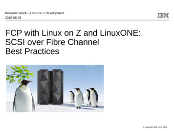
Can we use the same connectors? Yes!, the same forma factor has been used since 1GFC– At every speed increase there have been tweaks to the certain area of the connector and plug but same form factor.– Single lane QSFP was adopted for the 128GFC, 4 lanes of 32Gb– 4 lanesSFPQSFP
What is the Difference BetweenMulti-Mode and Single ModeFiber Types?
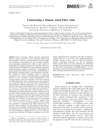
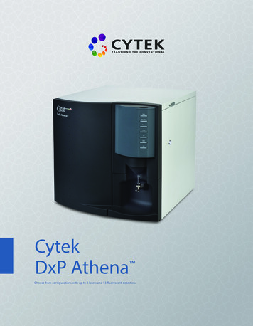
Multi-Mode Fiber (MMF)Specifically designed for use with typically “cheaper” light sources.– Has an extremely wide core, allowing the use of less precisely focused, aimed,and calibrated light sources.– But this comes at the expense of long-distance reach. Fiber is so named because it allows multiple ”modes” of light to propagate. “Modal dispersions” typically limit distances to “tens to hundreds” of meters.Types of Multi-Mode– OM1/OM2: found with orange fiber jackets. OM1 has a 62.5 micron (µm) core, OM2 has a 50µm core. Originally designed for 100M/1310nm signals, starts to fail at 16G speeds.– OM3/OM4 aka “laser optimized”: found with “aqua” fiber jackets. Specifically designed for modern 850nm short reach laser sources. Supports 16G signals at much longer distances (300m, vs 26m on OM1, approx.). Required for 32G/128G signals (which are really both 32G signals), 100m.
Single Mode Fiber (SMF)The fiber used for high bandwidths, and long distances.– Has a much smaller core size, between 8-10 microns (µm).– No inherent distance limitations caused by modal dispersion Can easily transmit a signal several thousand kilometers (with appropriateamplification), without requiring regeneration. Typically supports distances of 80km even without amplification.SMF has an even broader array of types than MMF.– OS1 ”tight buffered” for indoor use, OS2 “loose” for buried use.– ”Classic” SMF can be called “SMF-28” (a Corning product name)– But it also comes in many different formulations of Low Water Peak Fiber(LWPF), Dispersion Shifted Fiber (DSF), Non-Zero Dispersion ShiftedFiber, Bend Insensitive Fiber, etc, etc, etc.
Multi-Mode (MMF) and Single Mode Fiber (SMF)
Multi-Mode (MMF) and Single Mode Fiber (SMF)
Why is Bit Error Rate Importantin Fibre Channel?
Why is BER Important? Measures the data transmission performance of your system You want your transmissions to be as lossless as possible One Decimal out of place can cause a lot of trouble.– 1000.00 vs. 100.00 BER, Bit Error Rate / Bit Error Ratio– Bit Error Rate number of errors during a certain time unit Bit Error Ratio FC definition, “is the number of bits outputfrom a receiver that differ from the correct transmitted bits, divided by thenumber of transmitted bits”.– A bit error is any received bit that has been distorted in someway.
BER FC requires a raw BER of less than or equal to 10-12 up to 16GFC 32GFC calls for a raw BER of less than or equal to 10-6 becauseat 32GFC, 256B/257B encoding which includes Forward ErrorCorrection (FEC). Combined this give a BER of better than 10-12 When using 10GBASE-T, FCoE requires Cat6a or Cat7 to meet10-12 requirements
In Conclusion The reliability of Fibre Channel allows for many cabling optionsgoing from 1 meter to 10 kilometers The design goal should be to ensure simplicity for easiermanagement, future expansion, and serviceability Structure cabling can help meet that goal Fibre Channel merges the performance and reliability of localstorage with the connectivity and distance of networks
Q&A
Our Next FCIA Webcast:FICON 101June 19, 201810:00 am PTRegister at:https://www.brighttalk.com/webcast/14967/315723
After this Webcast Please rate this event – we value your feedback We will post a Q&A blog at http://fibrechannel.org/ with answers to allthe questions we received today Follow us on Twitter @FCIAnews for updates on future FCIA webcasts Visit our library of FCIA on-demand webcasts athttp://fibrechannel.org/webcasts/ to learn about:––––––Fibre Channel FundamentalsFC-NVMeLong Distance Fibre ChannelFibre Channel SpeedmapFCIP (Extension): Data Protection and Business ContinuityFibre Channel Performance
Every Data Center's cabling infrastructure is on a spectrum between a fully . Telecommunications Industry Association (TIA). In the United States, the ANSI/ TIA-568-D and ANSI/TIA-942-B standards help to ensure a proper cabling installation. Why is Structured Cabling Necessary?