Transcription
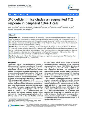
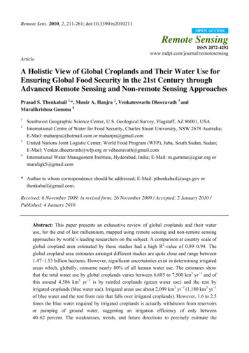
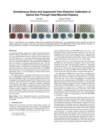
Simultaneous Direct and Augmented View Distortion Calibration ofOptical See-Through Head-Mounted Displays(a)Yuta Itoh Gudrun Klinker†Technical University of MunichTechnical University of Munich(b)(a)(c)(b)(d)(c)(d)Figure 1: Demonstration of our calibration method (with a professional OST-HMD setup). A user-perspective camera captures the world andscreen images from a viewpoint of test data. (a) Conventional automated calibration (Full INDICA [6]). (b) With image distortion corrected. (c)With scene distortion corrected. (d) Our proposed method correcting both of the two distortions simultaneously.A BSTRACTIn Augmented Reality (AR) with an Optical See-Through HeadMounted Display (OST-HMD), the spatial calibration between auser’s eye and the display screen is a crucial issue in realizing seamless AR experiences. A successful calibration hinges upon propermodeling of the display system which is conceptually broken downinto an eye part and an HMD part. This paper breaks the HMD partdown even further to investigate optical aberration issues. The display optics causes two different optical aberrations that degrade thecalibration quality: the distortion of incoming light from the physical world, and that of light from the image source of the HMD.While methods exist for correcting either of the two distortions independently, there is, to our knowledge, no method which correctsfor both simultaneously.This paper proposes a calibration method that corrects both ofthe two distortions simultaneously for an arbitrary eye positiongiven an OST-HMD system. We expand a light-field (LF) correction approach [8] originally designed for the former distortion. Ourmethod is camera-based and has an offline learning and an onlinecorrection step. We verify our method in exemplary calibrationsof two different OST-HMDs: a professional and a consumer OSTHMD. The results show that our method significantly improves thecalibration quality compared to a conventional method with the accuracy comparable to 20/50 visual acuity. The results also indicatethat only by correcting both the distortions simultaneously can improve the quality.Index Terms: H.5.1 [Information Interfaces and Presentation]:Multimedia Information Systems—Artificial, augmented, and virtual realities1I NTRODUCTIONMaintaining the consistency between virtual objects and the realworld (e.g. visually, temporally, and spatially) is the fundamentalrequirement for realizing an immersive, indistinguishable AR experience with OST-HMDs. The spatial consistency requires an ac e-mail:† e-mail:itoh@in.tum.deklinker@in.tum.decurate calibration between an OST-HMD and a user’s eye, i.e. theregistration between a physical object in the direct view and a corresponding virtual content in the augmented view. The successfulcalibration hinges upon a proper modeling of the eye-HMD system– a virtual projector-camera system with an image screen of theHMD as the projector screen and a user’s eye as the camera.Previous works [13, 3, 4, 6, 7] break the system down into an eyeand HMD part, and model them separately. The eye part involvesmodeling an eye optics and locating the eyeball w.r.t. the displaycoordinate system [6, 7, 14]. The HMD part involves modeling theimage screen. The previous works estimate model parameters bymeasuring the eye and/or the HMD screen by cameras. This workfocuses on the latter with this objective, camera-based approach.For calibrating the HMD part, an issue often over-looked is twooptical aberrations caused by the optical media of OST-HMDs:Direct-View Distortion (DVD) and Augmented-View Distortion(AVD) (See Fig. 2 too). DVD is the distortion of incoming lightrays from the real world through an OST-HMD to a user’s eye andAVD is the image distortion of a perceived image. A common OSTHMD design employs an optical combiner to guide the light froma light source of an OST-HMD to a user’s eye [16]. As the result,the user perceives the light ray as if it appears as a virtual imagefloating mid air or at infinity in the user’s view (Fig. 2 left). Sincethe combiner is an optical medium, it inevitably refracts light rayspassing through itself [16] including those from a physical objectin the world, i.e. DVD, and image light rays from the OST-HMD,i.e. AVD (Fig. 2 right).The intricacy of these distortions is that the amount of each distortion depends on where and at what angle a light ray hits the combiner and passes through its medium, i.e., each user viewpoint suffers from different amounts of both distortions. Furthermore, due tothe imperfection of the display optics, the image light rays may suffer from additional aberration out of the design during its passagethrough various optical media from the light source to the combiner.Importantly, DVD and AVD share the same distortion characteristic in part (Fig. 2). Consider a light ray from an eye towards theoptical combiner, the ray first reaches to the half-mirror of the combiner while refracted by the medium. The ray is then split into twopaths: one towards the world and the other the light source while receiving additional aberrations separately. D/AVD thus consist of ashared distortion part and a individual part. This paper and existingworks, however, do not explicitly separate these mixture model.
IdealDistortedHalf mirrorEyemodelWorldlightMediumEyemodelLight sourceWorldlightLight sourceFigure 2: Schematic visualization of optical aberrations in an OSTHMD system. (Left) Ideal case. (Right) A practical case where theA/DVD present in the system. If we back-trace a ray from an eye, onenotices that both distortions partially share a distortion path.While methods exist for correcting either of the distortions independently, there is, to our knowledge, no method handling bothdistortions simultaneously for an arbitrary eye position w.r.t. anHMD screen.Adapting existing AVD correction methods to DVD is notstraightforward. They model the image screen of an OST-HMDas a 3D plane/surface for modeling AVD. Such modeling does nottransfer to DVD directly. Our recent work proposes a camera-basedcalibration which corrects DVD for arbitrary eye positions based ona 4D light-field model [8]. This method treats DVD as a mappingbetween original and distorted light-fields; learns the mapping vianon-parametric regression from a training data set offline; and computes DVD for a given new eye-position online. Under the lightfield model, the AVD can be treated in a similar manner.We propose a camera-based calibration method that corrects bothdistortions simultaneously for arbitrary eye positions given an OSTHMD system. Our method adapts the light-field approach to AVDand has an offline/online step. The offline step learns a cascadedmapping which consists of two light-field mappings correspondingto each distortion. The online step applies the cascaded mapping togiven 3D world points and returns 2D image points. The 2D pointswill appear on a distorted image plane and will match the 3D points,which are also distorted, from the user’s current viewpoint.The evaluation with two OST-HMDs (a professional and a consumer OST-HMD) show that our model significantly improves thecalibration quality compared to a conventional HMD model and theprevious DVD-only model. The results also indicate that only correcting both distortions simultaneously can improve the quality.We discuss limitations of the current approach mostly due to thelimited capabilities of current OST-HMDs, and conclude by notingsome open questions toward practical OST-HMD calibrations.Contributions: 1. Providing a calibration method which corrects the D/AVD of OST-HMDs simultaneously for arbitrary eyepositions. 2. Demonstrating that the method improves the calibration quality of two OST-HMDs. The qualities are comparable up toa human eye of 20/50 visual acuity. 3. Showing, with a reasoning,that only correcting both distortions can improve the final quality.2R ELATED W ORKA key of successful calibration is how to model the eye-HMD system. Although eye model is equivalently important, this sectionfocuses on the HMD model which holds both DVD and AVD.2.1Direct-View Distortion of OST-HMDOur previous work [8] tackles the DVD by employing the light-fieldcorrection approach. Our approach aims at capturing the opticalcharacteristics of OST-HMDs as the shift of optical rays.2.2Augmented-View Distortion of OST-HMDsA user perceives an image of an OST-HMD as a virtual screen floating in mid air. For correct registration, we need to know how thisimage appears in a user perspective view. We categorize existingapproaches in three types: parametric and semi-/non-parametric.Parametric Approach Parametric approaches model thescreen images as a certain class of functions. A common approachis to treat the image produced by an OST-HMD as a 3D plane floating in mid air [17, 3, 2, 9, 1]. Under this model, an OST-HMDsystem is treated as an off-axis pinhole camera.This model, however, is incapable of describing real OST-HMDoptics. Owen et al. [13] demonstrate that the plane model does notcoincide with a 3D geometry of the display measured via triangulation, and they propose a curved 3D surface model. Their surfacemodel respects the spherical distortion caused by a curved mirrorin their OST-HMD, which falls into the first-order radial distortionmodel. Robinett and Rolland [15] use the same distortion model.Hua et al. [5] apply a similar model to their head-mounted projective display. Lee and Hua [11] extend the surface model to 6th orderradial distortions and tangential distortion.These approaches have a common drawback in the change ofthe user’s eye position w.r.t the HMD screen. Since the optics of anOST-HMD may distort the light of an image pixel differently at different viewpoints, the above models, learned at a single viewpoint,can cause registration errors when the eye position changes.Semi-Parametric Approach Wientapper et al. [18] proposea semi-parametric model for Head-Up Displays (HUDs). HUDsare essentially the same as OST-HMDs except that their images arereflected on the wind shields of vehicles. Their model combinesthe 3D-plane and a view-dependent polynomial model. The latter employs a higher-order polynomial function of 5 parameters:a 2D image point and a 3D eye position. We call their modelsemi-parametric since their polynomial model is essentially nonparametric, which is based on local data points and is representedby a linear sum of polynomial kernels.Non-Parametric Approach Klemm et al. [10] upgrade the 3Dplane model by triangulating every pixel of an OST-HMD screenvia the photogrammetry with structured image patterns. Their nonparametric, point-cloud approach requires an additional user adaptation since a few millimeters of error in the viewpoint positioncauses non-negligible registration errors.Recall that the refraction of an optical medium causes the AVD.The amount of refraction depends on which path the ray takesthrough in the medium – a light field (LF) of an image changesthe shape based on the user’s eye position.We adapt our original light-field model used for the DVD – wemodel the image screen as a function of light rays defined by 4Drays and learn the function via non-parametric kernel regression.3 M ETHODWe first explain the DVD and the AVD correction separately. Wethen introduce a unified approach. The notations are same as [8].3.1 Direct-View Distortion CorrectionFollowing our previous work [8], let D lW a light ray in the worldcoordinate system as a 4D Lumigraph: D lW : l(tEW , xWS , RSW , tSW ) : l(xWS ) R4 . See Sec. 3.3 of [8] for the exact definition.The DVD causes a distorted ray D lW0 . Given a set of (D lW ,D lW0 )measured from various viewpoints within the eyebox of the HMD,our LF correction approach in [8] gives a function D f (·) so thatD f (D l ) is close to D l 0 via a non-parametric kernel regression.WW3.2 Augmented-View Distortion CorrectionWe measure the LF of the OST-HMD screen in a similar way asin the previous section. Instead of letting a camera see 3D worldpoints through the medium of the HMD, we let the camera capturethe image of the image screen such that the camera can identifywhich image pixel is corresponding to that of the camera sensor.Let uSE R2 be an image pixel of a camera which correspondsto uS R2 , an image pixel of the virtual screen of the HMD. Let
1.3.Augmented ViewuS′uSEuEt2.uSEOptics4.Direct view:HMDKE R3 3 be the intrinsic matrix of the user-perspective cameraeSlocated at tEW . We compute a point K 1· denotes theE uE , where ehomogeneous vector. Given a 6DoF pose between the eye and theworld coordinate systems as (REW , tEW ), an eye sees a ray A lW0 asA 0 1 1lW : l(tEW , REW KE ueSE tEW , RSW , tSW ) l(REW KE ueSE tEW ). (1)Al0 R4 is a distorted ray since uSE contains the AVD already. Wedefine an original ray A lW virtually: a ray that would appear as uS ifthere were not for AVD and if the 3D plane model were correct. Letα a scale parameter with a unit of [meter/pixel], then A lW becomes,WAlW : l (tEW , αRSW ueS tSW , RSW , tSW ) l(αRSW ueS tSW ) R4 . (2)Finally, we learn a function A f 1 (·) so that A f 1 (A lW0 ) is close toA l . We now introduce a way to correct D/AVD simultaneously.W3.3 Unified Distortion CorrectionFor aligned visualization, a world point and a corresponding imagepoint must eventually travel along the same light path from the combiner to the eye. However, D lW reaches the user’s eye as D f (D lW )after having undergone the DVD; the corresponding virtual ray A lWas A f (A lW ) after AVD. The virtue of these LFs is that they are defined in a common coordinate system: they share the same u-v andthe s-t plane of the 4D lumigraph. We can thus directly bypass bothdistortion effects.Our goal is to achieve A f (A lW ) D f (D lW ). Since D lW is definedin the same space as A lW , we may apply the inverse of the AVD:A l A f 1 (D f (D l )). Thus, if u corresponds to A l , then u andWWSWSthe corresponding 3D point in the world align in the
Figure 2: Schematic visualization of optical aberrations in an OST-HMD system. (Left) Ideal case. (Right) A practical case where the A/DVD present in the system. If we back-trace a ray from an eye, one notices that both distortions partially share a distortion path. While methods exist for