Transcription
MD71-HB1Intel Socket LGA3647 processor motherboardUser ManualRev. 1.0
Copyright 2019 GIGA-BYTE TECHNOLOGY CO., LTD. All rights reserved.The trademarks mentioned in this manual are legally registered to their respective owners.DisclaimerInformation in this manual is protected by copyright laws and is the property of GIGABYTE.Changes to the specifications and features in this manual may be made by GIGABYTEwithout prior notice. No part of this manual may be reproduced, copied, translated, transmitted, orpublished in any form or by any means without GIGABYTE's prior written permission.Documentation ClassificationsIn order to assist in the use of this product, GIGABYTE provides the following types of documentation:User Manual: detailed information & steps about the installation, configuration and use thisproduct (e.g. motherboard, server barebones), covering hardware and BIOS.User Guide: detailed information about the installation & use of an add-on hardware orsoftware component (e.g. BMC firmware, rail-kit) compatible with this product. Quick Installation Guide: a short guide with visual diagrams that you can reference easily forinstallation purposes of this product (e.g. motherboard, server barebones).Please see the support section of the online product page to check the current availability of thesedocuments For More InformationFor related product specifications, the latest firmware and software, and other information, please visitour website at: http://www.gigabyte.com.For GIGABYTE distributors and resellers, additional sales & marketing materials are available from ourreseller portal: http://reseller.b2b.gigabyte.comFor further technical assistance, please contact your GIGABYTE representative or visithttp://esupport.gigabyte.com/ to create a new support ticket.For any general sales or marketing enquires, you may message GIGABYTE server directly byemail: server.grp@gigabyte.com.
Table of ContentsMD71-HB1 Motherboard Layout.5Block Diagram.7Chapter 1 Hardware Installation.81-11-21-31-4Installation Precautions. 8Product Specifications. 9Installing and Removing the CPU and Heat Sink. 11Installing and Removing Memory. 121-4-11-4-21-4-31-51-61-71-86-Channel Memory Configuration .12Installing and Removing a Memory Module .13DIMM Population Table .13Installing the M.2 SSD Module. 14Back Panel Connectors. 15Internal Connectors. 16Jumper Settings. 25Chapter 2 BIOS Setup.262-12-2The Main Menu. 28Advanced Menu. -102-2-112-2-122-2-132-2-142-3Trusted Computing.32Redfish Host Interface Settings.33Serial Port Console Redirection.34SIO Configuration.38PCI Subsystem Settings.39USB Configuration.40Post Report Configuration.41NVMe Configuration.42Chipset Configuration.43Network Stack Configuration.44iSCSI Configuration.45Intel(R) X722 Gigabit Network Connection.46VLAN Configuration.48Driver Health.50Chipset Setup Menu. 512-3-12-3-22-3-32-3-4Processor Configuration.52Common RefCode Configuration.54UPI Configuration.55Memory Configuration.57-3-
2-3-52-3-62-3-72-3-82-3-92-3-102-3-112-4Server Management Menu. 712-4-12-4-22-4-32-4-42-4-52-52-72-8Secure Boot .79Boot Menu. 812-6-1UEFI USB Drive BBS Priorities .832-6-22-6-3UEFI NETWORK Drive BBS Priorities . 84UEFI Application Boot Priorities . 85Save & Exit Menu. 86BIOS POST Codes. System Event Log.73View FRU Information.74BMC VLAN Configuration.75BMC Network Configuration.76IPv6 BMC Network Configuration.77Security Menu. 782-5-12-6IIO Configuration.59Advanced Power Management Configuration.61PCH Configuration.63Miscellaneous Configuration.65Server ME Configuration.66Runtime Error Logging Settings.67Power Policy.69AMI Standard - PEI.88AMI Standard - DXE.88AMI Standard - ERROR.90Intel UPI POST Codes.91Intel UPI Error Codes.91Intel MRC POST Codes.92Intel MRC Error Codes.92Intel PM POST Codes.93Intel PM POST Codes.93BIOS POST Beep code (AMI standard). 942-9-12-9-2PEI Beep Codes.94DXE Beep Codes.94-4-
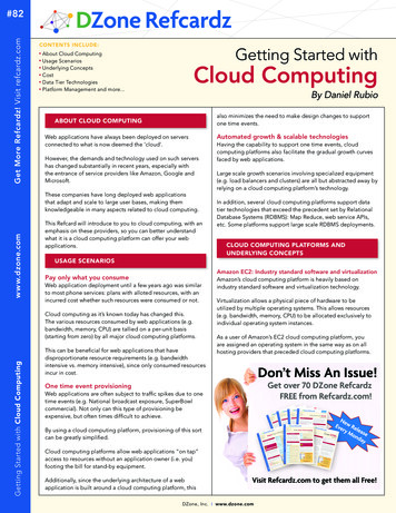
MD71-HB1 Motherboard Layout14223456784433323130292846212019CPU145DIMM P0 F0DIMM P0 E0DIMM P0 D02726252423229DIMM P1 J0DIMM P1 K0DIMM P1 L03443CPU0DIMM P0 A0DIMM P0 B0DIMM P0 C03537 38 39 40 41DIMM P1 I0DIMM P1 H0DIMM P1 G036101118 17 16 15 14 13 12-5-
8293031323334353637383940414243444546CodeSW IDUSB3 MLANLAN1LAN2LAN3 4SYS FAN5VGA 1P12V AUX2PMBUSATX1P12V AUX1CPU0 FANP12V AUX3F USB3SATA1SATA0SSATA0SYS FAN4SYS FAN3IPMBSSATA5SATA DOM2SSATA4LAN4 ACTSATA DOM1SW RAIDLAN3 ACTM2 SK1FP 1BP 1CASE OPENSYS FAN2SYS FAN1LPC TPMCOM1PCIE 1PCIE 2PCIE 3PCIE 4PCIE 5PCIE 6CPU1 FANPCIE 7M2 SK2BATLED BMCDescriptionID Button with LEDServer Management LAN Port (Top)/ USB 3.0 Ports (Bottom)GbE Ethernet LAN Port #1GbE Ethernet LAN Port #2GbE Ethernet LAN Port #3 (Top)/GbE LAN port #4 (Bottom)System Fan Connector #5VGA Port2x4 Pin 12V Power Connector (for CPU1)PMBus Connector2x12 Pin Main Power Connector2x4 Pin 12V Power Connector (for CPU0)CPU Fan Connector (for CPU0)2x5 Pin 12V Power Connector (for PCIe Slot)Front Panel USB 3.0 ConnectorSlimline Connector #1 (SATA 6Gb/s Signal/ for SATA#4 #7)Slimline Connector #0 (SATA 6Gb/s Signal/ for SATA#0 #3)Slimline Connector #0 (SATA 6Gb/s Signal/ for sSATA#0 #3)System Fan Connector #4System Fan Connector #3IPMB ConnectorSATA 6Gb/s Connector #5SATA DOM Support Power Connector for SSATA Port #5SATA 6Gb/s Connector #4LAN#4 Active LEDSATA DOM Support Power Connector for SSATA Port #4SATA RAID Upgrade KeyLAN#3 Active LEDM.2 Slot #1 (PCIe Gen3 x4, Support NGFF-2260/2280)Front Panel HeaderHDD Back Plane Board ConnectorCase Open Intrusion Alert HeaderSystem Fan Connector #2System Fan Connector #1TPM ConnectorSerial Port Cable ConnectorPCIe x16 slot #1 (Gen3 x16)PCIe x8 slot #2 (Gen3 x8)PCIe x16 slot #3 (Gen3 x16)PCIe x8 slot #4 (Gen3 x8)PCIe x16 slot #5 (Gen3 x16)PCIe x16 slot #6 (Gen3 x16)CPU Fan Connector (for CPU1)PCIe x16 slot #7 (Gen3 x16)M.2 slot #2 (PCIe Gen3 x4, Support NGFF-2260/2280)Ba ery SocketBMC Firmware Readiness LED-6-
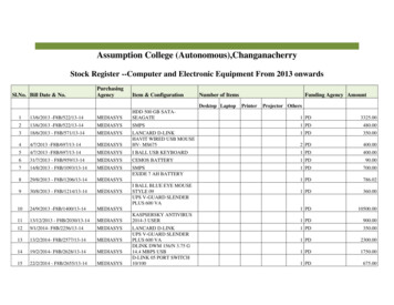
Block Diagram-7-
Chapter 11-1Hardware InstallationInstallation PrecautionsThe motherboard contains numerous delicate electronic circuits and components which canbecome damaged as a result of electrostatic discharge (ESD). Prior to installation, carefully readthe user's manual and follow these procedures: Prior to installation, do not remove or break motherboard S/N (Serial Number) sticker orwarranty sticker provided by your dealer. These stickers are required for warranty validation. Always remove the AC power by unplugging the power cord from the power outlet beforeinstalling or removing the motherboard or other hardware components. When connecting hardware components to the internal connectors on the motherboard,make sure they are connected tightly and securely. When handling the motherboard, avoid touching any metal leads or connectors. It is best to wear an electrostatic discharge (ESD) wrist strap when handling electroniccomponents such as a motherboard, CPU or memory. If you do not have an ESD wriststrap, keep your hands dry and first touch a metal object to eliminate static electricity. Prior to installing the motherboard, please have it on top of an antistatic pad or within anelectrostatic shielding container. Before unplugging the power supply cable from the motherboard, make sure the powersupply has been turned off. Before turning on the power, make sure the power supply voltage has been set according tothe local voltage standard. Before using the product, please verify that all cables and power connectors of yourhardware components are connected. To prevent damage to the motherboard, do not allow screws to come in contact with themotherboard circuit or its components. Make sure there are no leftover screws or metal components placed on the motherboard orwithin the computer casing. Do not place the computer system on an uneven surface. Do not place the computer system in a high-temperature environment. Turning on the computer power during the installation process can lead to damage tosystem components as well as physical harm to the user. If you are uncertain about any installation steps or have a problem related to the use of theproduct, please consult a certified computer technician.Hardware Installation-8-
1-2Product Specifications CPU 2nd Generation Intel Xeon Scalable ProcessorsIntel Xeon Platinum Processor, Intel Xeon Gold Processor,Intel Xeon Silver Processor and Intel Xeon Bronze Processor2 x LGA 3647, Socket PRecommended FAN Module: Dynatron B5CPU TDP Up to 205WNOTE: If only 1 CPU is installed, some PCIe or memory functions might be unavailableChipset Memory Onboard Graphics LAN Expansion Slots Intel C622 Express Chipset12 x DIMM SlotsDDR4 Memory Supported Only6-Channel Memory ArchitectureRDIMM Modules Up to 64GB SupportedLRDIMM Modules Up to 128GB Supported1.2V Modules: 2933/2666/2400 MHzIntegrated in Aspeed AST25002D Video Graphic Adapter with PCIe Bus Interface1920x1200@60Hz 32bpp, DDR4 SDRAM2 x 10Gb/s BASE-T LAN Ports2 x 1Gb/s LAN Ports1 x 10/100/1000 Management LANSlot 7: 1 x PCIe x16 (Gen3 x16 bus) Slot from CPU 1Slot 6: 1 x PCIe x16 (Gen3 x16 bus) Slot from CPU 1Slot 5: 1 x PCIe x16 (Gen3 x16 bus) Slot from CPU 1Slot 4: 1 x PCIe x8 (Gen3 x8 bus) Slot from CPU 1, shared with Slot 5Slot 3: 1 x PCIe x16 (Gen3 x16 bus) Slot from CPU 0Slot 2: 1 x PCIe x8 (Gen3 x8 bus) Slot from CPU 0, shared with M.2 PCIe x4 busSlot 1: 1 x PCIe x16 (Gen3 x16 bus) Slot from CPU 0Storage Interface 2 x M.2 Slots:- M-key- PCIe Gen3 x4 per Slot- Supports NGFF-22110/2280 Cards- From CPU 03 x SlimSAS for 12 x SATA III 6Gb/s Ports2 x 7-pin SATA III 6Gb/s with SATA DOM SupportedRAIDIntel SATA RAID 0/1/10/5 -9-Hardware Installation
Internal I/OConnectors 1 x 24-pin ATX Main Power Connector 2 x 8-pin ATX 12V Power Connectors 2 x SATA DOM Power Pin Headers 3 x SlimSAS Connectors 2 x 7-pin SATA Connectors 2 x M.2 Slots 2 x CPU Fan Headers 5 x System Fan Headers 1 x USB 3.0 Header 1 x COM Header 1 x LPC TPM Header 1 x VROC Connector 1 x Front Panel Header 1 x HDD Back Plane Board Header 1 x PMBus Connector 1 x IPMB Connector 1 x Clear CMOS Jumper 1 x BIOS Recovery Jumper 1 x Case Open HeaderRear I/O 2 x USB 3.0 PortsConnectors 1 x VGA Port 4 x RJ45 Ports 1 x MLAN Port 1 x ID Button with LED 1 x TPM Header with LPC InterfaceTPM Optional TPM2.0 kit: CTM000Board Aspeed AST2500 Management ControllerManagement GIGABYTE Management Console (AMI MegaRAC SP-X) web interface E-ATXForm Factor 305mm W x 330mm DGIGABYTE reserves the right to make any changes to the product specifications and product-relatedinformation without prior notice.Hardware Installation- 10 -
1-3Installing and Removing the CPU and Heat SinkRead the following guidelines before you begin to install the CPU: Make sure that the motherboard supports the CPU. Always turn off the computer and unplug the power cord from the power outlet before installingthe CPU to prevent hardware damage. Unplug all cables from the power outlets. Disconnect all telecommunication cables from their ports. Place the system unit on a flat and stable surface. Open the system according to the instructions.WARNING!Failure to properly turn off the server before you start installing components may cause seriousdamage. Do not attempt the procedures described in the following sections unless you are aqualified service technician.Follow these instructions to Install the CPU:1.2.3.4.5Align and install the processor on the carrier.Apply thermal compound evenly on the top of the CPU. Remove the protective cover from theunderside of the heat sink.Carefully flip the heatsink over. Then install the carrier assembly on the bottom of the heatsink andmake sure the gold arrow is located in the correct direction.Remove the CPU cover.Note: Save and replace the CPU cover if the processor is removed from its socket.Align the heatsink with the CPU socket by the guide pins and make sure the gold arrow is located in thecorrect direction. Then place the heatsink onto the top of the CPU socket.To secure the heatsink, tighten the screws in a sequential order (1g2g3g4).Note: When dissambling the heatsink, loosen the screws in reverse order (4g3g2g1)Note:32131244- 11 -Hardware Installation
1-4Installing and Removing MemoryRead the following guidelines before you begin to install the memory: Make sure that the motherboard supports the memory. It is recommended to use memory of thesame capacity, brand, speed, and chips. Always turn off the computer and unplug the power cord from the power outlet before installingthe memory to prevent hardware damage. Memory modules have a foolproof design. A memory module can be installed in only onedirection. If you are unable to insert the memory, switch the direction.1-4-1 6-Channel Memory ConfigurationHardware Installation- 12 -CPU0DIMM P1 J0DIMM P1 K0DIMM P1 L0CPU1DIMM P0 A0DIMM P0 B0DIMM P0 C0DIMM P0 F0DIMM P0 E0DIMM P0 D0DIMM P1 I0DIMM P1 H0DIMM P1 G0This motherboard provides 12 DDR4 memory sockets and supports 6-Channel Technology. After the memoryis installed, the BIOS will automatically detect the specifications and capacity of the memory.
1-4-2 Installing and Removing a Memory ModuleBefore installing a memory module, make sure to turn off the computer and unplug thepower cord from the power outlet to prevent damage to the memory module.Be sure to install DDR4 UDIMMs on this motherboard.Follow these instructions to install a DIMM module:1.Insert the DIMM memory module vertically into the DIMM slot and push it down.2.Close the plastic clip at both edges of the DIMM slots to lock the DIMM module.3.Reverse the installation steps when you want to remove the DIMM module.212Note: When popula ng DIMMs into a channel, slot numbers having the suffix “0” must be populated first,then followed by slot numbers having the suffix “1”.1-4-3 DIMM Population TableSpeed (MT/s); Voltage (V);TypeDIMM Capacity (GB)Ranks Per DIMMand Data GBRDIMM 3DSDIMM per Channel (DPC)1 Slot Per ChannelDRAM DensityRDIMMRDIMMRDIMMRDIMMSlots per Channel(SPC) and1.2V2933* 4Gb DRAM density is only supported on speeds up to 2666MT/s.Hardware Installation- 13 -
1-5Installing the M.2 SSD ModuleFollow the steps below to install a M.2 SSD module on your motherboard.Step1. Insert the M.2 SSD module into the slot.Step2. Secure it with the screw, tightening as necessary to fasten the M.2 SSD module in place.21224222602280- 14 -Hardware Installation
1-6Back Panel Connectorszvxuy{ wu VGA PortThe video-in port allows connection via video in, which can also apply to the video loop thru function.v RJ-45 LAN Port #3The Gigabit Ethernet LAN port provides Internet connection at up to 1 Gbps data rate. See the sectionbelow for a description of the states of the LAN port LEDs.w RJ-45 LAN Port #4The Gigabit Ethernet LAN port provides Internet connection at up to 1 Gbps data rate. See the sectionbelow for a description of the states of the LAN port LEDs.x 10GBASE-T RJ-45 LAN Port #2The 10 Gigabit Ethernet LAN port provides Internet connection at up to 10 Gbps data rate. See thesection below for a description of the states of the LAN port LEDs.y 10GBASE-T RJ-45 LAN Port #1The 10 Gigabit Ethernet LAN port provides Internet connection at up to 10 Gbps data rate. See thesection below for a description of the states of the LAN port LEDs.z Server Management LAN PortThe LAN port provides Internet connection with data transfer speeds of 10/100/1000Mbps. This port isthe dedicated LAN port for Server Management.{ USB 3.0 PortsThe USB port supports the USB 3.0 specification. Use this port for USB devices such as a USBkeyboard/mouse, USB printer, USB flash drive etc. ID button with LEDWhen the system identification is active, the ID LED on the front/ back panel glows blue.Connection/Speed LEDLink/Activity LEDLAN Port10GbE LAN LED:StateYellow OnGreen OnOff10/100/1000 LAN LED:Description5Gbps, 2.5Gbps, 1Gps data rate10Gbps data rate100Mbps data rateStateYellow OnGreen OnOffDescription1Gbps data rate100Mbps data rate10Mbps data rateID button/LED:StateDescriptionBule On System identification is activeOffSystem identification is disabled When removing the cable connected to a back panel connector, first remove the cable from yourdevice and then remove it from the motherboard. When removing the cable, pull it straight out from the connector. Do not rock it side to side toprevent an electrical short inside the cable connector.Hardware Installation- 15 -
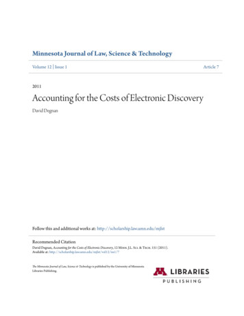
1-7Internal Connectors161132117CPU1DIMM P1 J0DIMM P1 K0DIMM P1 L0DIMM P1 I0DIMM P1 H0DIMM P1 G0191213252322DIMM P0 F0DIMM P0 E0DIMM P0 D0CPU0DIMM P0 A0DIMM P0 B0DIMM P0 C02697245862014121518 4 101)ATX114)SYS FAN32)P12V AUX1 (for CPU0)15)SYS FAN43)P12V AUX2 (for CPU1)16)SYS FAN54)P12V AUX3 (for PCIe Slot)17)PMBUS5)SSATA418)F USB36)SSATA519)COM17)SATA DOM1 (for SSATA4)20)IPMB8)SATA DOM2 (for SSATA5)21)LPC TPM9)SW RAID22)FP 110)CPU0 FAN23)BP 111)CPU1 FAN24)LAN3 ACT/ LAN4 ACT12)SYS FAN125)BAT13)SYS FAN226)LED BMCRead the following guidelines before connecting external devices: First make sure your devices are compliant with the connectors you wish to connect. Before installing the devices, be sure to turn off the devices and your computer. Unplug the powercord from the power outlet to prevent damage to the devices. After installing the device and before turning on the computer, make sure the device cable hasbeen securely attached to the connector on the motherboard.- 16 Hardware Installation
1/2/3/4) ATX1/P12V AUX1/P12V AUX2/P12V AUX3(2x12 Main Power Connector and 2x4/2x5 12V Power Connector)With the use of the power connector, the power supply can supply enough stable power to all the componentson the motherboard. Before connecting the power connector, first make sure the power supply is turned offand all devices are properly installed. The power connector possesses a foolproof design. Connect the powersupply cable to the power connector in the correct orientation. The 12V power connector mainly suppliespower to the CPU. If the 12V power connector is not connected, the computer will not start.To meet expansion requirements, it is recommended that a power supply that can withstand highpower consumption be used (500W or greater). If a power supply is used that does not provide therequired power, the result can lead to an unstable or unbootable system.P12V AUX2P12V AUX1/P12V AUX2Pin No.123456785 1ATX18 4P12V AUX1P12V AUX3ATX11324112Pin No.123456789101112DefinitionGNDGNDGNDGND 12V 12V 12V 12VP12V AUX3DefinitionPin No.3.3V133.3V14GND15 5V16GND17 5V18GND19Power Good205VSB21 12V22 12V233.3V24Hardware InstallationDefinition3.3V-12VGNDPS ONGNDGNDGND-5V 5V 5V 5VGND- 17 -10651Pin No.12345678910DefinitionGNDGNDGNDGNDGND 12V 12V 12V 12V 12V
5/6) SSATA4/SSATA5 (SATA 6Gb/s Connectors)The SATA connectors conform to SATA 6Gb/s standard and are compatible with SATA 3Gb/s standard. EachSATA connector supports a single SATA device.17(Support SATA DOM Power)SSATAIII 4Pin No.1234567DefinitionGNDTXPTXNGNDRXNRXPGNDSSATAIII 57/8) SATA DOM1/ SATA DOM2 Power ConnectorSATA-DOM (Disk on Module) is available to allow for standalone boot and diagnostics direct through SATAconnections on the board.3311Pin No.123SATA DOM1Definition5V for SATA DOMGNDNo ConnectSATA DOM2- 18 -Hardware Installation
9) SW RAID (SATA RAID Upgrade Key)41Pin No.1234SW RAIDDefinitionGNDP 3V3 AUXGNDPCH SATA RAID KEY10/11/12/13/14/15/16) CPU0 FAN/CPU1 FAN/SYS FAN1/SYS FAN3/SYS FAN2/SYS FAN4SYS FAN5 (CPU Fan/System Fan Headers)The motherboard has one 4-pin CPU fan header (CPU FAN), and two 4-pin (SYS FAN) system fan headers.Most fan headers possess a foolproof insertion design. When connecting a fan cable, be sure to connectit in the correct orientation (the black connector wire is the ground wire). The motherboard supports CPUfan speed control, which requires the use of a CPU fan with fan speed control design. For optimum heatdissipation, it is recommended that a system fan be installed inside the chassis.CPU1 FANSYS FAN511SYS FAN1SYS FAN2SYS FAN3SYS FAN4Pin No.1234DefinitionGND 12VSenseSpeed ControlCPU0 FAN Be sure to connect fan cables to the fan headers to prevent your CPU and system fromoverheating. Overheating may result in damage to the CPU or the system may hang. These fan headers are not configuration jumper blocks. Do not place a jumper cap on theheaders.Hardware Installation- 19 -
17) PMBus ConnectorThe Power Management Bus (PMBus) is a variant of the System Management Bus (SMBus) which istargeted at digital management of power supplies.1PMBus5Pin No.12345DefinitionPMBus ClockPMBus DataPMBus AlertGND3.3V Sense18) F USB3 (USB 3.0 Header)The header conform to USB 2.0/ 3.0 specification. Each USB header can provide two USB ports via anoptional USB bracket. For purchasing the optional USB bracket, please contact the local dealer.USB 3.0 HeaderPin No. Definition10 111 20Pin No. Definition1Power11IntA P2 D 2IntA P1 SSRX-12IntA P2 D-3IntA P1 SSRX 13GND4GND14IntA P2 SSRX 5IntA P1 SSRX-15IntA P2 SSRX-6IntA P1 SSRX 16GND7GND17IntA P2 SSRX 8IntA P1 D-18IntA P2 SSRX-9IntA P1 D 19Power10NC20No PinF USB3- 20 -Hardware Installation
19) COM1 (Serial Port Cable Connector)The COM header can provide one serial port via an optional COM port cable. For purchasing the optionalCOM port cable, please contact the local dealer.COM112910Pin TSNCTSNRINo Pin20) IPMB (Intelligent Platform Management Bus) ConnectorThe Intelligent Platform Management Bus Communications Protocol defines a byte-level transport fortransferring Intelligent Platform Management Interface Specification (IPMI) messages between intelligent I2Cdevices.41IPMBHardware Installation- 21 -Pin No.1234DefinitionClockGNDDataVCC
21) LPC TPM (Trusted Platform Module Connector)Trusted Platform Module (TPM) is an international standard for a secure cryptoprocessor, a dedicatedmicrocontroller designed to secure hardware through integrated cryptographic keys.1 2LPC TPM13 14Pin No. DefinitionPin No. Definition1Clock8No Connect2P 3V3 AUX9LPC LAD 23LPC RST10No Pin4P3V311LPC LAD 35LPC LAD 012GND6IRQ SERIAL13LPC FRAME N7LPC LAD 114GND22) FP 1 (Front Panel Header)Connect the power switch, reset switch, speaker, chassis intrusion switch/sensor and system status indicatoron the chassis to this header according to the pin assignments below. Note the positive and negative pinsbefore connecting the cables.1 223 24Pin No. DefinitionFP 1Pin No. Definition1Power LED 13GND25V Standby14LAN1 Link LED-3No Pin15Reset Button4ID LED 16SMBus Data5Power LED-17GND6ID LED-18SMBus Clock7HDD LED 19ID Button8System Status LED 20Case Open9HDD LED-21GND10System Status LED-22LAN2 Active LED 11Power Button23NMI Switch12LAN1 Active LED 24LAN2 Link LED-The front panel design may differ by chassis. A front panel module mainly consists of power switch,reset switch, power LED, hard drive activity LED, speaker etc. When connecting your chassis frontpanel module to this header, make sure the wire assignments and the pin assignments are matchedcorrectly.- 22 Hardware Installation
23) BP 1 (HDD Backplane Board Header)1229 30BP 1Pin No. DefinitionPin No. Definition1Reserved2BPMI DIN/OUT3GND4BPMI DOUT/IN5BPMI LOAD6GND7BPMI CLK8PLD Program EN9GLED AMB N10GLED GRN N11FAN IRQ N12Reserved13BP SCL14GND15BP SDA16BP RST N17SMB U2 TMP SCL18GND19SMB U2 TMP SDA2012C DEV RST21PH HP SCL022GND23PH HP SDA024GND25PH HP SCL126GND27PH HP SDA128GND29P3V3 AUX30P3V3 AUX24) LAN3 ACT/ LAN4 ACT (LAN3 and LAN4 Active LED Header)12Pin No. DefinitionLAN3 ACTLAN4 ACTHardware Installation- 23 -1Enable LAN Link/ Active LED2P 3V3 AUX
25) BAT (Battery Scoket)The battery prov
The motherboard contains numerous delicate electronic circuits and components which can become damaged as a result of electrostatic discharge (ESD). Prior to installation, carefully read the user's manual and follow these procedures: Prior to installation, do not remove or break motherboard S/N (Serial Number) sticker or