Transcription
GA-H61M-DS2User's ManualRev. 100212ME-H61MDS2-1002R
MotherboardGA-H61M-DS2Jul. 29, 2011GA-H61M-DS2MotherboardJul. 29, 2011
Copyright 2011 GIGA-BYTE TECHNOLOGY CO., LTD. All rights reserved.The trademarks mentioned in this manual are legally registered to their respective owners.DisclaimerInformation in this manual is protected by copyright laws and is the property of GIGABYTE.Changes to the specifications and features in this manual may be made by GIGABYTE withoutprior notice. No part of this manual may be reproduced, copied, translated, transmitted, orpublished in any form or by any means without GIGABYTE's prior written permission. In order to assist in the use of this product, carefully read the User's Manual. For product-related information, check on our website at: http://www.gigabyte.comIdentifying Your Motherboard RevisionThe revision number on your motherboard looks like this: "REV: X.X." For example, "REV: 1.0"means the revision of the motherboard is 1.0. Check your motherboard revision before updatingmotherboard BIOS, drivers, or when looking for technical information.Example:
Table of ContentsGA-H61M-DS2 Motherboard Layout.5GA-H61M-DS2 Motherboard Block Diagram.6Chapter 1 Hardware Installation.71-11-21-31-41-51-61-7Installation Precautions. 7Product Specifications. 8Installing the CPU. 10Installing the Memory.11Installing an Expansion Card.11Back Panel Connectors. 12Internal Connectors. 13Chapter 2 BIOS 3Startup Screen. 20The Main Menu. 21MB Intelligent Tweaker(M.I.T.). 22Standard CMOS Features. 28Advanced BIOS Features. 29Integrated Peripherals. 31Power Management Setup. 32PC Health Status. 34Load Fail-Safe Defaults. 35Load Optimized Defaults. 36Set Supervisor/User Password. 36Save & Exit Setup. 37Exit Without Saving. 37Chapter 3 Drivers Installation.38-4-
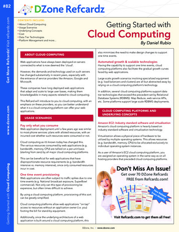
GA-H61M-DS2 Motherboard LayoutATX 12VKB MSVGALGA1155CPU FANR USBATXDDR3 1BATGA-H61M-DS2PCIEX16M BIOSPCIEX1 1B BIOSCODECPCIEX1 2Intel H61 SYS FANLPTCOMAF USB1F USB2SATA2 3 SATA2 1F AUDIOAtherosGbE LANiTEIT8728AUDIODDR3 2USB LANSATA2 0SATA2 2CLR CMOSF PANELBox ContentsGA-H61M-DS2 motherboardMotherboard driver diskUser's ManualTwo SATA cablesI/O ShieldThe box contents above are for reference only and the actual items shall depend on the product package you obtain.-5-
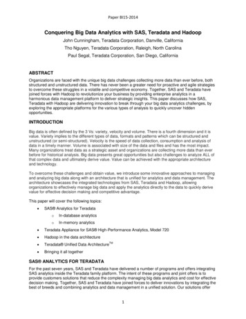
GA-H61M-DS2 Motherboard Block Diagram1 PCI Express x16CPU CLK /- (100 MHz)LGA1155CPUDDR3 1333/1066/800 MHzDual Channel MemoryDMI 2.0x16PCI Express BusFDIPCIe CLK(100 MHz)Dual BIOSD-Sub4 SATA 3Gb/sIntel H61PCI Express Busx18 USB 2.0/1.1x1AtherosGbE LANPCIe CLK(100 MHz)LPCBusRJ45LPTCOM PortLANCODECMIC (Center/Subwoofer Speaker Out)Line Out (Front Speaker Out)Line In (Rear Speaker Out)2 PCI Express x1iTEIT8728-6-PS/2 KB/Mouse
Chapter 11-1Hardware InstallationInstallation PrecautionsThe motherboard contains numerous delicate electronic circuits and components which canbecome damaged as a result of electrostatic discharge (ESD). Prior to installation, carefully readthe user's manual and follow these procedures: Prior to installation, do not remove or break motherboard S/N (Serial Number) sticker orwarranty sticker provided by your dealer. These stickers are required for warranty validation. Always remove the AC power by unplugging the power cord from the power outlet beforeinstalling or removing the motherboard or other hardware components. When connecting hardware components to the internal connectors on the motherboard,make sure they are connected tightly and securely. When handling the motherboard, avoid touching any metal leads or connectors. It is best to wear an electrostatic discharge (ESD) wrist strap when handling electronic components such as a motherboard, CPU or memory. If you do not have an ESD wrist strap,keep your hands dry and first touch a metal object to eliminate static electricity. Prior to installing the motherboard, please have it on top of an antistatic pad or within anelectrostatic shielding container. Before unplugging the power supply cable from the motherboard, make sure the power supply has been turned off. Before turning on the power, make sure the power supply voltage has been set according tothe local voltage standard. Before using the product, please verify that all cables and power connectors of your hardware components are connected. To prevent damage to the motherboard, do not allow screws to come in contact with themotherboard circuit or its components. Make sure there are no leftover screws or metal components placed on the motherboard orwithin the computer casing. Do not place the computer system on an uneven surface. Do not place the computer system in a high-temperature environment. Turning on the computer power during the installation process can lead to damage to system components as well as physical harm to the user. If you are uncertain about any installation steps or have a problem related to the use of theproduct, please consult a certified computer technician.-7-
1-2Product SpecificationsCPU Support for Intel Core i7 processors/Intel Core i5 processors/Intel Core i3 processors/Intel Pentium processors/Intel Celeron processorsin the LGA1155 package(Go to GIGABYTE's website for the latest CPU support list.) L3 cache varies with CPUChipset Intel H61 Express ChipsetMemory 2 x 1.5V DDR3 DIMM sockets supporting up to 16 GB of system memoryOnboardGraphics Dual channel memory architecture Support for DDR3 1333/1066/800 MHz memory modules Support for non-ECC memory modules (Go to GIGABYTE's website for the latest supported memory speeds and memorymodules.) Chipset:- 1 x D-Sub portAudio* Due to Windows 32-bit operating system limitation, when more than 4 GB of physicalmemory is installed, the actual memory size displayed will be less than 4 GB. Realtek/VIA HD audio codec High Definition Audio 2/4/5.1/7.1-channel* To configure 7.1-channel audio, you have to use an HD front panel audio module andenable the multi-channel audio feature through the audio driver.LAN 1 x Atheros GbE LAN chip (10/100/1000 Mbit)Expansion Slots 1 x PCI Express x16 slot, running at x16 2 x PCI Express x1 slots(All PCI Express slots conform to PCI Express 2.0 standard.)Storage Interface Chipset:- 4 x SATA 3Gb/s connectors supporting up to 4 SATA 3Gb/s devicesUSB Chipset:- Up to 8 USB 2.0/1.1 ports (4 ports on the back panel, 4 ports available throughthe internal USB headers)Internal 1 x 24-pin ATX main power connector 1 x 4-pin ATX 12V power connectorConnectors 4 x SATA 3Gb/s connectors 1 x CPU fan header 1 x system fan header 1 x front panel header 1 x front panel audio header 2 x USB 2.0/1.1 headers 1 x parallel port header 1 x serial port header 1 x clearing CMOS jumper-8-
Back PanelConnectors I/O Controller iTE IT8728 chipHardwareMonitor BIOS Unique Features BundledSoftwareOperatingSystemForm Factor 1 x PS/2 keyboard port1 x PS/2 mouse port1 x D-Sub port4 x USB 2.0/1.1 ports1 x RJ-45 port3 x audio jacks (Line In/Line Out/Microphone)System voltage detectionCPU/System temperature detectionCPU/System fan speed detectionCPU fan speed control* Whether the CPU fan speed control function is supported will depend on the CPUcooler you install.2 x 32 Mbit flashUse of licensed AWARD BIOSSupport for DualBIOS PnP 1.0a, DMI 2.0, SM BIOS 2.4, ACPI 1.0bSupport for @BIOSSupport for Q-FlashSupport for Xpress BIOS RescueSupport for Download CenterSupport for Xpress InstallSupport for Xpress Recovery2Support for EasyTune* Available functions in EasyTune may differ by motherboard model.Support for Smart 6 Support for Auto GreenSupport for ON/OFF ChargeSupport for Cloud OCSupport for 3TB UnlockSupport for Q-Share Norton Internet Security (OEM version) Support for Microsoft Windows 7/Vista/XP Micro ATX Form Factor; 22.6cm x 17.4cm* GIGABYTE reserves the right to make any changes to the product specifications and product-related informationwithout prior notice.-9-
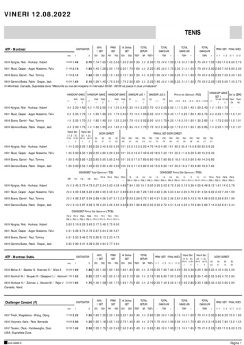
1-3Installing the CPURead the following guidelines before you begin to install the CPU: Make sure that the motherboard supports the CPU.(Go to GIGABYTE's website for the latest CPU support list.) Always turn off the computer and unplug the power cord from the power outlet before installingthe CPU to prevent hardware damage. Locate the pin one of the CPU. The CPU cannot be inserted if oriented incorrectly. (Or you maylocate the notches on both sides of the CPU and alignment keys on the CPU socket.) Apply an even and thin layer of thermal grease on the surface of the CPU. Do not turn on the computer if the CPU cooler is not installed, otherwise overheating and damage of the CPU may occur. Set the CPU host frequency in accordance with the CPU specifications. It is not recommendedthat the system bus frequency be set beyond hardware specifications since it does not meet thestandard requirements for the peripherals. If you wish to set the frequency beyond the standardspecifications, please do so according to your hardware specifications including the CPU, graphics card, memory, hard drive, etc.Installing the CPUA. Locate the alignment keys on the motherboard CPU socket and the notches on the CPU.LGA1155 CPU SocketAlignment KeyAlignment KeyPin One Corner of the CPU SocketLGA1155 CPUNotchTriangle Pin One Marking on the CPU- 10 -Notch
1-4Installing the MemoryRead the following guidelines before you begin to install the memory: Make sure that the motherboard supports the memory. It is recommended that memory of thesame capacity, brand, speed, and chips be used.(Go to GIGABYTE's website for the latest supported memory speeds and memory modules.) Always turn off the computer and unplug the power cord from the power outlet before installingthe memory to prevent hardware damage. Memory modules have a foolproof design. A memory module can be installed in only one direction. If you are unable to insert the memory, switch the direction.Dual Channel Memory ConfigurationDDR3 1DDR3 2This motherboard provides two DDR3 memory sockets and supports Dual Channel Technology. After thememory is installed, the BIOS will automatically detect the specifications and capacity of the memory. Enabling Dual Channel memory mode will double the original memory bandwidth.The two DDR3 memory sockets are divided into two channels and each channel has one memory socket asfollowing:Channel A: DDR3 1Channel B: DDR3 2Due to CPU limitations, read the following guidelines before installing the memory in Dual Channel mode.111 Dual Channel mode cannot be enabled if only one DDR3 memory module is installed.222 When enabling Dual Channel mode with two memory modules, it is recommended that memory ofthe same capacity, brand, speed, and chips be used for optimum performance.1-5Installing an Expansion CardRead the following guidelines before you begin to install an expansion card: Make sure the motherboard supports the expansion card. Carefully read the manual that camewith your expansion card. Always turn off the computer and unplug the power cord from the power outlet before installingan expansion card to prevent hardware damage.- 11 -
1-6Back Panel ConnectorsPS/2 Keyboard and PS/2 Mouse PortUse the upper port (green) to connect a PS/2 mouse and the lower port (purple) to connect a PS/2 keyboard.D-Sub PortThe D-Sub port supports a 15-pin D-Sub connector. Connect a monitor that supports D-Sub connectionto this port.USB 2.0/1.1 PortThe USB port supports the USB 2.0/1.1 specification. Use this port for USB devices such as a USB keyboard/mouse, USB printer, USB flash drive and etc.RJ-45 LAN PortThe Gigabit Ethernet LAN port provides Internet connection at up to 1 Gbps data rate. The followingdescribes the states of the LAN port LEDs.Connection/Speed LEDActivity LEDLAN PortConnection/Speed LED:StateOrangeGreenOffActivity LED:Description1 Gbps data rate100 Mbps data rate10 Mbps data rateStateDescriptionBlinking Data transmission or receiving is occurringOffNo data transmission or receiving is occurringLine In Jack (Blue)The default line in jack. Use this audio jack for line in devices such as an optical drive, walkman, etc.Line Out Jack (Green)The default line out jack. Use this audio jack for a headphone or 2-channel speaker. This jack can beused to connect front speakers in a 4/5.1/7.1-channel audio configuration.Mic In Jack (Pink)The default Mic in jack. Microphones must be connected to this jack.To configure 7.1-channel audio, you have to use an HD front panel audio module and enable themulti-channel audio feature through the audio driver. When removing the cable connected to a back panel connector, first remove the cable from yourdevice and then remove it from the motherboard. When removing the cable, pull it straight out from the connector. Do not rock it side to side toprevent an electrical short inside the cable connector.- 12 -
1-7Internal Connectors1321275411101)2)3)4)5)6)ATX 12VATXCPU FANSYS FANSATA2 0/1/2/3F PANEL987)8)9)10)11)12)6F AUDIOF USB1/2COMALPTCLR CMOSBATRead the following guidelines before connecting external devices: First make sure your devices are compliant with the connectors you wish to connect. Before installing the devices, be sure to turn off the devices and your computer. Unplug thepower cord from the power outlet to prevent damage to the devices. After installing the device and before turning on the computer, make sure the device cable hasbeen securely attached to the connector on the motherboard.- 13 -
1/2) ATX 12V/ATX (2x2 12V Power Connector and 2x12 Main Power Connector)With the use of the power connector, the power supply can supply enough stable power to all the components on the motherboard. Before connecting the power connector, first make sure the power supplyis turned off and all devices are properly installed. The power connector possesses a foolproof design.Connect the power supply cable to the power connector in the correct orientation. The 12V power connector mainly supplies power to the CPU. If the 12V power connector is not connected, the computer willnot start.To meet expansion requirements, it is recommended that a power supply that can withstand highpower consumption be used (500W or greater). If a power supply is used that does not providethe required power, the result can lead to an unstable or unbootable system.ATX 12V:2143ATX 12VPin No.1234DefinitionGNDGND 12V 12VATX:1224113Pin No.123456789101112DefinitionPin No.3.3V133.3V14GND15 5V16GND17 5V18GND19Power Good205VSB (stand by 5V)21 12V22 12V (Only for 2x12-pin ATX) 233.3V (Only for 2x12-pin ATX) 24ATX- 14 -Definition3.3V-12VGNDPS ON (soft On/Off)GNDGNDGND-5V 5V 5V 5V (Only for 2x12-pin ATX)GND (Only for 2x12-pin ATX)
3/4) CPU FAN/SYS FAN (Fan Headers)The motherboard has a 4-pin CPU fan header (CPU FAN) and a 4-pin system fan header (SYS FAN).Most fan headers possess a foolproof insertion design. When connecting a fan cable, be sure to connectit in the correct orientation (the black connector wire is the ground wire). The motherboard supports CPUfan speed control, which requires the use of a CPU fan with fan speed control design. For optimum heatdissipation, it is recommended that a system fan be installed inside the chassis.CPU FAN:Pin No.12341CPU FANDefinitionGND 12VSenseSpeed ControlSYS FAN:Pin No.12341SYS FANDefinitionGND 12VSenseReserveDEBUGDEBUGPORT PORTDEBUGDEBUGPORT PORT Be sure to connect fan cables to the fan headers to prevent your CPU and system from overheating. Overheating may result in damage to the CPU or the system may hang. These fan headers are not configuration jumper blocks. Do not place a jumper cap on the headers.5) SATA2 0/1/2/3 (SATA 3Gb/s Connectors)The SATA connectors conform to SATA 3Gb/s standard and are compatible with SATA 1.5Gb/s standard.Each SATA connector supports a single SATA device.77SATA2 1SATA2 0SATA2 3SATA2 211Pin No.1234567DefinitionGNDTXPTXNGNDRXNRXPGNDPlease connect the L-shaped end ofthe SATA cable to your SATA harddrive.- 15 -
6) F PANEL (Front Panel Header)Connect the power switch, reset switch, speaker, and system status indicator on the chassis to thisheader according to the pin assignments below. Note the positive and negative pins before connectingthe cables.PowerSwitchHard Drive ResetActivity LED SwitchSPEAK-Power LEDChassis IntrusionHeader MSG/PWR (Message/Power/Sleep LED):Connects to the power status indicator on the chassis front panel. The LEDSystem Status LEDBIOS Switcher (X58A-OC)is on when the system is operating. The LED is off when the system is inS0OnS3/S4/S5OffS3/S4 sleep state or powered off (S5).1DB PORTF PANEL(H61M-D2)PWR-2019HD HDRESRES CICI 21PWR F PANEL(NH)F AUDIO(H)SpeakerSPEAK MSG MSGPW PW-Message/Power/Sleep LED1M SATA PW (Power Switch):Connects to the power switch on the chassis front panel. You may configure the way to turn off yoursystem using the power switch (refer to Chapter 2, "BIOS Setup," "Power Management Setup," forVoltage measurement module(X58A-OC)more information).PWM Switch (X58A-OC) SPEAK (Speaker):Connects to the speaker on the chassis front panel. The system reports system startup status by isDIP short beep will be heard if no problem is detected at system startup. Ifsuing a beep code. One singlea problem is detected, the BIOS may issue beeps in different patterns to indicate the problem.PCIe power connector(SATA)(X58A-OC)HD (HardDrive Activity LED):Connects to the hard drive activity LED on the chassis front panel. The LED is on when the hard driveis reading or writing data. RES (Reset Switch):Connects to the reset switch on the chassis front panel. Press the reset switch to restart the computerif the computer freezes and fails to perform a normal restart. CI (Chassis Intrusion Header):Connects to the chassis intrusion switch/sensor on the chassis that can detect if the chassis coverhas been removed. This function requires a chassis with a chassis intrusion switch/sensor.1DIPDIP1 2 31 2 31DIP1 2 31 2 3The front panel design may differ by chassis. A front panel module mainly consists of powerswitch, reset switch, power LED, hard drive activity LED, speaker and etc. When connecting yourchassis front panel module to this header, make sure the wire assignments and the pin assignments are matched correctly.- 16 -
7) F AUDIO (Front Panel Audio Header)The front panel audio header supports Intel High Definition audio (HD) and AC'97 audio. You may connectyour chassis front panel audio module to this header. Make sure the wire assignments of the module connector match the pin assignments of the motherboard header. Incorrect connection between the moduleconnector and the motherboard header will make the device unable to work or even damage it.91012For HD Front Panel Audio:Pin No. Definition1MIC2 L2GND3MIC2 R4-ACZ DET5LINE2 R6GND7FAUDIO JD8No Pin9LINE2 L10GNDFor AC'97 Front Panel Audio:Pin No. Definition1MIC2GND3MIC Power4NC5Line Out (R)6NC7NC8No Pin9Line Out (L)10NC The front panel audio header supports HD audio by default. Audio signals will be present on both of the front and back panel audio connections simultaneously. Some chassis provide a front panel audio module that has separated connectors on each wireinstead of a single plug. For information about connecting the front panel audio module thathas different wire assignments, please contact the chassis manufacturer.8) F USB1/2 (USB 2.0/1.1 Headers)The headers conform to USB 2.0/1.1 specification. Each USB header can provide two USB ports via anoptional USB bracket. For purchasing the optional USB bracket, please contact the local dealer.910Pin No.1234567891012DefinitionPower (5V)Power (5V)USB DXUSB DYUSB DX USB DY GNDGNDNo PinNC Do not plug the IEEE 1394 bracket (2x5-pin) cable into the USB header. Prior to installing the USB bracket, be sure to turn off your computer and unplug the powercord from the power outlet to prevent damage to the USB bracket.- 17 -
9) COMA (Serial Port Header)The COM header can provide one serial port via an optional COM port cable. For purchasing the optional COM port cable, please contact the local dealer.910Pin NRTSNCTSNRINo PinDEBUGPORT10) LPT (Parallel Port Header)The LPT header can provide one parallel port via an optional LPT port cable. For purchasing the optionalLPT port cable, please contact the local dealer.2526Pin No.12345678910111213- 18 D512Pin 7GNDACKGNDBUSYGNDPENo PinSLCTGND
11) CLR CMOS (Clearing CMOS Jumper)Use this jumper to clear the CMOS values (e.g. date information and BIOS configurations) and resetthe CMOS values to factory defaults. To clear the CMOS values, place a jumper cap on the two pins totemporarily short the two pins or use a metal object like a screwdriver to touch the two pins for a fewseconds.Open: NormalShort: Clear CMOS Values Always turn off your computer and unplug the power cord from the power outlet before clearing the CMOS values. After clearing the CMOS values and before turning on your computer, be sure to remove thejumper cap from the jumper. Failure to do so may cause damage to the motherboard. After system restart, go to BIOS Setup to load factory defaults (select Load Optimized Defaults) or manually configure the BIOS settings (refer to Chapter 2, "BIOS Setup," for BIOSconfigurations).12) BAT (Battery)The battery provides power to keep the values (such as BIOS configurations, date, and time information)in the CMOS when the computer is turned off. Replace the battery when the battery voltage drops to alow level, or the CMOS values may not be accurate or may be lost.You may clear the CMOS values by removing the battery:111 Turn off your computer and unplug the power cord.222 Gently remove the battery from the battery holder and wait for one minute.(Or use a metal object like a screwdriver to touch the positive and negativeterminals of the battery holder, making them short for 5 seconds.)333 Replace the battery.444 Plug in the power cord and restart your computer. Always turn off your computer and unplug the power cord before replacing the battery. Replace the battery with an equivalent one. Danger of explosion if the battery is replaced withan incorrect model. Contact the place of purchase or local dealer if you are not able to replace the battery byyourself or uncertain about the battery model. When installing the battery, note the orientation of the positive side ( ) and the negative side (-)of the battery (the positive side should face up). Used batteries must be handled in accordance with local environmental regulations.- 19 -
Chapter 2BIOS SetupTo access the BIOS Setup program, press the Delete key during the POST when the power is turned on.To see more advanced BIOS Setup menu options, you can press Ctrl F1 in the main menu of theBIOS Setup program.To upgrade the BIOS, use either the GIGABYTE Q-Flash or @BIOS utility. Q-Flash allows the user to quickly and easily upgrade or back up BIOS without entering the operatingsystem. @BIOS is a Windows-based utility that searches and downloads the latest version of BIOS from theInternet and updates the BIOS. Because BIOS flashing is potentially risky, if you do not encounter problems using the currentversion of BIOS, it is recommended that you not flash the BIOS. To flash the BIOS, do it withcaution. Inadequate BIOS flashing may result in system malfunction. It is recommended that you not alter the default settings (unless you need to) to prevent systeminstability or other unexpected results. Inadequately altering the settings may result in system'sfailure to boot. If this occurs, try to clear the CMOS values and reset the board to default values.(Refer to the "Load Optimized Defaults" section in this chapter or introductions of the battery/clearing CMOS jumper in Chapter 1 for how to clear the CMOS values.)2-1Startup ScreenThe following screens may appear when the computer boots.A. The LOGO Screen (Default):Function KeysB. The POST ScreenAward Modular BIOS v6.00PGCopyright (C) 1984-2011, Award Software, Inc.Motherboard ModelBIOS VersionH61M-DS2 E4. DEL : BIOS Setup F9 : XpressRecovery2 F12 : Boot Menu End : Qflash07/14/2011-H61-7A89XG05C-00- 20 -Function Keys
2-2The Main MenuOnce you enter the BIOS Setup program, the Main Menu (as shown below) appears on the screen. Use arrow keys to move among the items and press Enter to accept or enter a sub-menu.(Sample BIOS Version: E4)CMOS Setup Utility-Copyright (C) 1984-2011 Award Software MB Intelligent Tweaker(M.I.T.)Standard CMOS FeaturesAdvanced BIOS FeaturesIntegrated PeripheralsPower Management SetupPC Health StatusESC: QuitF8: Q-FlashLoad Fail-Safe DefaultsLoad Optimized DefaultsSet Supervisor PasswordSet User PasswordSave & Exit SetupExit Without Saving : Select ItemF10: Save & Exit SetupF11: Save CMOS to BIOSF12: Load CMOS from BIOSChange CPU's Clock & Voltage If you do not find the settings you want in the Main Menu or a submenu, press Ctrl F1 toaccess more advanced options. When the system is not stable as usual, select the Load Optimized Defaults item to set yoursystem to its defaults. The BIOS Setup menus described in this chapter are for reference only and may differ by BIOSversion. The Functions of the F11 and F12 keys (For the Main Menu Only) F11: Save CMOS to BIOSThis function allows you to save the current BIOS settings to a profile. You can create up to 8 profiles(Profile 1-8) and name each profile. First enter the profile name (to erase the default profile name, usethe SPACE key) and then press Enter to complete. F12: Load CMOS from BIOSIf your system becomes unstable and you have loaded the BIOS default settings, you can use thisfunction to load the BIOS settings from a profile created before, without the hassles of reconfiguring theBIOS settings. First select the profile you wish to load, then press Enter to complete.- 21 -
2-3MB Intelligent Tweaker(M.I.T.)CMOS Setup Utility-Copyright (C) 1984-2011 Award SoftwareMB Intelligent Tweaker(M.I.T.)}}}}}M.I.T Current StatusAdvanced Frequency SettingsAdvanced Memory SettingsAdvanced Voltage SettingsMiscellaneous SettingsBIOS VersionBCLKCPU FrequencyMemory FrequencyTotal Memory SizeE499.80 MHz3193.73 MHz1330.76 MHz1024 MBCPU Temperature36oCVcoreDRAM Voltage1.188 V1.584 VEnter: Select : MoveF5: Previous ValuesItem HelpMenu Level [Press Enter][Press Enter][Press Enter][Press Enter][Press Enter] /-/PU/PD: ValueF10: SaveF6: Fail-Safe DefaultsESC: ExitF1: General HelpF7: Optimized DefaultsWhether the system will work stably with the overclock/overvoltage settings you made is dependenton your overall system configurations. Incorrectly doing overclock/overvoltage may result in damage to CPU, chipset, or memory and reduce the useful life of these components. This page is foradvanced users only and we recommend you not to alter the default settings to prevent systeminstability or other unexpected results. (Inadequately altering the settings may result in system'sfailure to boot. If this occurs, clear the CMOS values and reset the board to default values.)CMOS Setup Utility-Copyright (C) 1984-2011 Award SoftwareMB Intelligent Tweaker(M.I.T.)}}}}}M.I.T Current StatusAdvanced Frequency SettingsAdvanced Memory SettingsAdvanced Voltage SettingsMiscellaneous Settings[Press Enter][Press Enter][Press Enter][Press Enter][Press Enter]BIOS VersionBCLKCPU FrequencyMemory FrequencyTotal Memory SizeE499.80 MHz3193.73 MHz1330.76 MHz1024 MBCPU Temperature36oCVcoreDRAM Voltage1.188 V1.584 VEnter: Select : MoveF5: Previous Values /-/PU/PD: ValueF10: SaveF6: Fail-Safe DefaultsItem HelpMenu Level ESC: ExitF1: General HelpF7: Optimized DefaultsThis sec
Support for Microsoft Windows 7/Vista/XP Form Factor Micro ATX Form Factor; 22.6cm x 17.4cm * GIGABYTE reserves the right to make any changes to the product specifications and product-related information