Transcription
PRO-RO6-Stage Reverse Osmosis SystemRev: 0615
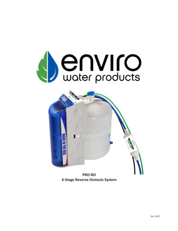
Introduction to the PRO-ROCongratulations on your purchase of the PRO-RO six stage reverse osmosis system. The PRO-RO features a four-stageprefilter, membrane and postfilter housed in a single cartridge. The final two stages consist of a granular activated carbonpolishing filter and a calcite remineralizing filter.When properly maintained, this system will provide you with years of trouble-free service. The next sections containimportant information on the proper care and maintenance of your system, please take a few minutes to read through thisinformation.The cartridges in this system must be replaced on a regular basis to maintain efficiency and to ensure high water quality.These cartridges work together and must be replaced every 6-12 months. Any significant change in performance of thesystem should be investigated promptly to avoid secondary damage or deterioration to other parts of the system.Normally, the reverse osmosis membrane is replaced during an annual filter change. However, if at any time you notice areduction in water production or an unpleasant taste in the reverse osmosis water, it could be time to replace themembrane. We recommend replacing the membrane when TDS reduction falls below 75%.CAUTION: Improperly installed systems could result in water damage due to leaks or flooding. Proper installation of thissystem requires familiarity with standard sink plumbing and proper use of common hand and power tools. If you are notfamiliar with standard sink plumbing and proper use of common hand and power tools or have any difficulty with theinstallation of this system, consult a licensed professional, such as a contractor or plumber.NOTE: This system has been designed for installation by licensed professionals, such as a contractor or plumber.StageDescriptionReplacementIntervalPart Number1-44-Stage Cartridge1) 20 micron sediment prefilter2) Granular activated carbon (GAC) prefilter3) Reverse osmosis membrane4) Granular activated carbon postfilter18 months104592NOL5-6Granular activated carbon (GAC) and calcite(remineralization) postfilter6-12 months104834NOLwww.envirowaterproducts.com3
Limited WarrantyThis Limited Warranty extends to the original purchaser of the system only. This warranty covers all Manufacturer-supplied items only thatprove to be defective in material, workmanship or factory preparation. This warranty covers parts only; all labor is excluded from this warranty, including, but not limited to, services related to the removal, replacement, installation, adjustment, maintenance and/or repair ofthe unit or its components items. excludes all non-Manufacturer labor required for any servicing of the unit, including, but not limited to,servicing related to installation, adjustment, maintenance and repair of the unit. This warranty applies only for the first full calendar yearfrom date of purchase. The following items are excluded from this warranty: membranes, filters, O-rings, and all other parts or components that require regular replacement as a result of ordinary usage.Disclaimers: This Limited Warranty applies only if the system is installed, used and maintained in compliance with all instructions andrequirements enclosed with the system. This warranty will be void for failure to observe the following conditions:1.2.3.4.5.6.7.8.9.The system is to be used with potable water from a municipal water system.Feed water pressure to the unit is no less than 40 PSI and no greater than 80 PSI.The system is to be used on water supplies with chlorine concentrations of 1.0 mg/L (ppm) or less.Feed water temperature to the unit must be no less than 40 F and no more than 100 F.Total dissolved solids in feed water must be less than 2,000 mg/L (ppm).Feed water must have a pH between 4 and 8.Turbidity must be less than 1.0 NTU.SDI must be less than 5.Feed water must be completely free of iron, manganese or hydrogen sulfide.Do not use with water that is microbiologically unsafe or of unknown quality without adequate disinfection before or after the system.The Manufacturer does not know the characteristics of your water supply. The quality of water supplies may vary seasonably or over aperiod of time. Your water usage may vary as well. Water characteristics can also change if the drinking water appliance is moved to a newlocation. The Manufacturer assumes no liability for the determination of the proper equipment necessary to meet your requirements, andwe do not authorize others to assume such obligation on our behalf.This Limited Warranty does not cover any Manufacturer-supplied items that are defective as a result of the use of improper parts, equipment or materials. This warranty does not cover alterations or modifications of the unit, or failure of a unit caused by such alterations andmodificationsThis Limited Warranty does not cover malfunctions of the unit due to tampering, misuse, alteration, lack of regular maintenance, misapplication, fouling due to hydrogen sulfide, manganese or iron, scaling from excessive hardness, turbidity greater than 1.0 NTU, Silt DensityIndex (SDI) greater than 5.0 SDI, or excessive membrane hydrolysis due to chlorine levels in excess of 1.0 mg/L (ppm). In addition, damageto the unit due to fire, accident, negligence, act of God, or events beyond the control of the Manufacturer are not covered by this warranty.Incidental and Consequential Damages Limitation: The Manufacturer will not be responsible for any incidental or consequential damagesas a result of the failure of this unit to comply with express or implied warranties or any defect in the unit, including but not limited to, losttime, inconvenience, damage to personal property, loss of revenue, commercial losses, postage, travel, telephone expenditures, or otherlosses of this nature. Some states do not allow the exclusion or limitation of incidental or consequential damages, so this exclusion maynot apply to you.Owner’s Warranty Responsibilities: As a condition of this Limited Warranty, the owner must ensure periodic maintenance of the systemis performed as described in the literature enclosed with the system. Neglect, improper maintenance, abuse, modification or alteration ofthe unit will invalidate this Warranty. Should your unit develop a defect or otherwise fail to perform in accordance with this warranty, youshould contact the retailer from whom the product was originally purchased.Implied Warranties: The implied at-law warranties of merchantability and fitness for a particular purpose shall terminate on the date oneyear after the date of purchase. Note: some states do not allow limitations on how long an implied warranty lasts, so the above limitationsmay not apply to you.Other Rights: This Warranty gives you specific legal rights and you may also have other rights which vary from state to state.www.envirowaterproducts.com4
System SpecificationsDimensions and WeightA.B.C.D.E.F.G.H.I.J.K.L.Product water storage tankTank valveTank tubing (3/8” white)Air-gap faucetDrain connection assemblyDrain tubing (3/8” white)Quick connect fittingDrain tubing (1/4” black)Faucet tubing (3/8” blue)Four-stage desalinatorFeed water tubing (1/4” green)Feed valve assembly (with adapter andshut-off valve).M. Two-stage remineralizing post-filterDGIFEMLHKBC (not shown)System Dimensions9.72” W x 13.75” D x 15.38” H( 24.7 x 34.9 x 39.1 cm), 11 lbs. (5 kg.)AJ(behind cover)This system has been designed for installation by a licensed professional such as a contractor or plumber. Proper completion of this installation will require basic familiarity with standard sink plumbing and proper use of common hand and power tools. Improperly installed systemscould result in water damage due to leaks or flooding.Performance SpecificationsMembrane ProductionSystemProductionTDS RejectionRecovery1Feed Water Requirements50 .5%26.76%System tested at 50 psig, 750ppm TDS at 77 F.The percentage of the feed water availableas reverse osmosis treated water undernormal operating conditions.140-80 psi (275 kPa - 552 kPa)40 F - 100 F (4 C - 38 C) 2000 mg/L 1.0 mg/L 1 NTU 54-8Feed water must be potable, municipal water. Mustbe free of potential membrane foulants such as Iron,Hydrogen Sulfide and Manganese.Do not use with water that is microbiologically unsafe or of unknown qualitywithout adequate disinfection before or after the system.www.envirowaterproducts.com5
Faucet Installation1. Drill a 1 1/4" hole for installation of the air-gap faucet on yourcountertop. If you already have a hole large enough, please seestep 2.2. Place the RO unit underneath the sink in the area you plan onhaving it for the final installation.3. Place the rubber seal onto base of faucet, fitting around thefaucet barbs.Escutcheon(attached)4. Put the faucet stem down through the countertop hole.5. From underneath the sink, slide the large washer, and thewhite plastic spacer, open end up, onto the threaded faucet stem,fitting around the faucet barbs.6. Place the lock washer onto the faucet stem. Thread the locknut onto the faucet stem.Rubber seal7. Orient the faucet on the countertop and then securely tightenthe lock nut.8. Push the 3/8" white tubing onto the 3/8" fitting (larger barb)located on the faucet base. See Fig. 2.CountertopCountertopLargewasher9. Push the 1/4" black drain tubing, attached to the system, ontothe 1/4" fitting (smaller barb) located on the faucet base.SpacerNote: Running the black and white tubing under warm water for2-3 minutes will soften the tubing and allow for easier installationon the two air-gap barbs.Lock washer10. Thread the faucet quick-connect adapter, located in the systemparts bag, onto the end of the the faucet stem.Lock nutFaucetconnectorNote: This connection should be hand-tightened only.11. Firmly push the end of the 3/8" blue tubing into this 3/8"adapter.Fig 1: Faucet and fittingsNote: The white tubing provided is typically longer than isrequired for your installation. Be sure to cut the white tubing tothe proper length to reach the drain installation (see followingpage). Discard any excess tubing.Large barb,3/8” white tubingFig 2: Closeup of faucet barbswww.envirowaterproducts.com6Small barb,1/4” black tubing
Feed and Drain ConnectionFeed Connection1. Locate and turn off the angle stop valve on the cold water line feeding the sink. This valve willusually be located under the sink on the pipe coming out of the wall.2. When the angle stop valve is closed, relieve pressure in the line by momentarily opening thecold water tap on the sink.3. Disconnect the cold water faucet feed line at the angle stop valve.Shut-off valve4. Install the feed valve assembly into the angle stop. (Fig. 1)Adapter5. Firmly press the green 1/4” tubing into the 1/4" connector on the feed valve assembly.6. Connect the cold water faucet feed line into the feed valve assembly.7. Make sure the small shut-off valve on the feed valve assembly is closed. Turn on the feed waterconnection valve. Check for leaks.7. Attach the small feed valve warning tag from the parts bag to the feed valve.8. Attach the Shutoff Warning label to the system so that it is directly visible. Fill out the Date ofInstallation label and attach to the side of the system.Drain Connection1. You will need an electric drill with a 3/8” bit and a screwdriver for this portion of the installation.Angle stopFig. 1Note: The feed valveadapter may beconfigured to fit eithera 3/8" or 1/2" anglestop connection bychanging the locationof the adapter.2. Obtain the drain saddle assembly, two 1 ½” bolts, two 3/8” hex nuts, and the small adhesivefoam pad from the small parts bag (Fig. 2).3. Place the adhesive foam pad on the inside of the the drain saddle front, aligning the holes.4. Position the drain saddle on the drain pipe under the sink between the “P” trap and the sinkconnection. Orient the drain saddle so that the opening is on the side of the drain pipe.5. Using the bolts and hex nuts, hand tighten the saddle bracket evenly until the saddle grips thepipe snugly. Use a Phillips screwdriver to fully tighten the bolts. Do not overtighten.6. If necessary, remove the drain saddle connector nut from the opening of the drain saddle.Using the connector opening in the side of the drain saddle as a guide, drill a 3/8" hole throughthe wall of the drain pipe.7. Extend the drain tubing from the RO dispensing faucet to the drain saddle and measure forlength. The tubing must be routed so that water can run downhill for the entire length of thetubing from the faucet. Avoid low spots or loops. Cut the tubing shorter, if necessary.8. Insert the drain tube from the R.O. dispensing faucet through the drain saddle connector nut.Tighten the connector nut onto the drain saddle.www.envirowaterproducts.com7Fig. 2Note: The drain saddleassembly must beinstalled before the 'P'trap. Do not install thedrain saddle assemblybetween the 'P' trapand the wall.
System Activation and FlushingSystem Activation and Inspection1. Check all tubing connections to ensure they are firmly seated. CHECK TO SEE THAT THE CARTRIDGE RETAINER CLIP ISPROPERLY ENGAGED AND LOCKED. Failure to keep the retaining clip in place will result in accidental leaks and flooding.2. Open the dispensing faucet at the sink. Close the tank shut-off valve. Make sure the feed valve for the incoming wateris open. Open the small feed shut-off valve on the green feed line.3. Observe all tubing and connections for several minutes to detect any leaks. In approximately 5 minutes, (assumingnormal feed water pressure) the dispensing faucet should begin dripping.4.Allow the faucet to run for up to 15 minutes, then close the faucet.5.Check for leaks at all connections.6.Open the tank shut-off valve.Initial Flushing Procedure1. Before the system can be used for drinking water production it must be adequately flushed. Each reservoir tank isdosed with a small amount of powdered sanitizer before shipment, typically a chlorinating agent, in order to ensure tankinternal cleanliness. Also, the carbon filter cartridge will release a small amount of carbon fines during the first tankful offlow. This flushing procedure will allow any sanitizer or carbon fines to pass from the system.2. Initial tank filling will take approximately one hour (based on average feed pressure). When the tank is full, the waterpressure will have risen to the point where the automatic shut-off valve inside the system will stop the feed flow throughthe system. Actuation of the automatic shut-off valve can be determined by either checking for a lack of brine flow to thedrain saddle, or by listening very closely near the dispensing faucet for absence of water flow sound though the air gap.When the tank has filled for the first time, it should be left undisturbed for at least 8 hours to ensure proper sanitization.3. After 8 hours has elapsed, open the dispensing faucet fully and allow the product water to run out to drain at maximumflow. The initial discharge will be dark with the bulk of the carbon particle wash out. There may also be the scent of chlorinated water from the sanitizing agent. When the flow has diminished to a fast drip or small stream, close the dispensingfaucet.4. Fill and flush the tank at least three times prior to use. If necessary, repeat until the chlorination scent has disappeared.It is important that the flush be done at maximum flow (e.g. the tank must be full) to assist in rapid wash out. After thisflushing procedure the system is ready for normal use.www.envirowaterproducts.com8
Installation Checklist1.System is located where it will not be subject to physical impacts or rough contact by heavy objects.2.Feed water pressure to the unit is no less than 40 psi and no greater than 80 PSI.3. Ensure the plastic retainer clip that holds the desalinator cartridge in place is fully engaged and locked in place. The slidelocks must snap into place in the slots. If the clip does not snap easily into place through the slots it means the cartridge is notfully inserted into the connectors. Press top or bottom of cartridge to engage connectors until it snaps into place properly.4.All tubing connections, especially push-in quick connections, are fully inserted.5. Tubing connected between the faucet and the drain saddle fitting (the fitting attached to the sink drain pipe) runs "downhill" to the drain. There should be no loops or places where water would not flow out to the drain.6.Feed water valve is open.7. Within one to two hours after initial application of water pressure, check again for leaks especially at the tank, faucet tubing and connectors. These parts will not see full pressure until approximately 2 hours after the system is activated.8.Flush three tankfuls of product water to drain. If a chlorine scent persists, repeat flushing procedure.www.envirowaterproducts.com9
MaintenanceCartridge Replacement1. Close the small shut-off valve on the feed valve assembly.2.Close the tank shut-off valve.3.Open the dispensing faucet to relieve system pressure. Close dispensing faucet when flow has stopped.4. Remove the cover from the front of the system. Remove the retaining clip. Pull the cartridge off the system evenly attop and bottom. Dispose of used cartridge.6. Install the new cartridge, rocking gently from side to side as necessary until the cartridge tubes are properly engaged inthe unit connectors. Install the retaining clip, ensuring the slide locks snap into place in the slots. If the clip does not snapeasily into place through the slots it means the cartridge is not fully inserted into the connectors. Press the top or bottom ofthe cartridge to engage the connector so that it snaps fully into place. Failure to properly install the retaining clip will resultin accidental leaks and flooding.7.Open the small shut-off valve on the feed valve assembly. Open the dispensing faucet.8.Close dispensing faucet after water starts running.9.Observe system for any leaks, especially at newly re placed cartridge.10. Open the tank shut-off valve.11. The system should be flushed at least once as described above under Section 8.Post Filter Replacement1. Close the small shut-off valve on the feed valve assembly.2.Close the tank shut-off valve.3.Open the dispensing faucet.4.Close the dispensing faucet when the water stops flowing.5.Locate the inline filter on the faucet line.6.Remove the tubing by depressing the collet towards the filter and pulling the blue tubing from the filter.7.Remove the other side of the blue tubing as described above.8.Reverse the above steps to install the new inline filter, making sure that the tubing is pressed in as far as possible.9. Open the small shut-off valve on the feed valve assembly. Observe system for any leaks, especially at newly re placedcartridge.10. Open the tank shut-off valve.11. The system should be flushed at least once as described in System Activation and Flushing.www.envirowaterproducts.com10
Please fill out the following information at the time of installation. Save for future reference.Model:Date Code:Install Date:Sold by:Installed By:Service CenterPhone Number:www.envirowaterproducts.com11
Congratulations on your purchase of the PRO-RO six stage reverse osmosis system. The PRO-RO features a four-stage . prefilter, membrane and postfilter housed in a single cartridge. . Improperly installed systems : could result in water damage due to leaks or flooding. A.oduct water storage tank Pr B.ank valve T C.ank tubing (3/8" white) T