Transcription
Design GuideData Center Interconnection with VXLANThe requirement to operate multiple, geographically dispersed data centers is a fact of life for many businessesand organizations today. There are many reasons for distributing applications and data in more than one datacenter, such as increasing levels of service availability, improving application performance and driving operationalefficiencies. Data center interconnection ensures that data is consistent, allows for the rapid movement ofvirtualized workloads, and facilitates the deployment of application high availability solutions between locations.This design guide describes an Arista solution for providing simple, robust, and cost-effective data centerinterconnection (DCI) that enables layer-2 services to be bridged between multiple sites over existing layer-3 IPnetworks. This solution is completely standards-based and can be deployed over existing routed TCP/IP transportnetworks. Based on multi-chassis link aggregation (MLAG) and Virtual eXtensible Local Area Network (VXLAN), itprovides a highly available DCI framework for linking two or more data centers. It requires no special hardwareand can be deployed using any Arista switching hardware that supports VXLAN MLAG.arista.com
Design GuideTable of contentsTHE DRIVERS FOR DATA CENTER INTERCONNECTION3DATA CENTER INTERCONNECTION TECHNOLOGIES4PSEUDOWIRE & TUNELLING SOLUTIONS4VXLAN: A SCALABLE, STANDARDS-BASED DCI SOLUTION5INTRODUCING THE ARISTA NETWORKS DCI WITH VXLAN SOLUTIONMAC LEARNING AND THE FORWARDING OF BROADCAST & MULTICAST TRAFFICARISTA DCI SOLUTION COMPONENTS566ARISTA NETWORKS VXLAN HARDWARE VTEP GATEWAY7LICENSING & PLATFORM SUPPORT8ARISTA MULTI-CHASSIS LINK AGGREGATION (MLAG)8ARISTA VXLAN MLAG SOLUTION10DEPLOYING THE ARISTA VXLAN DCI SOLUTIONINTEGRATING ARISTA DCI SOLUTION WITH EXISTING NETWORKSCONFIGURATION EXAMPLE111113THE PHYSICAL TOPOLOGY13THE MLAG TOPOLOGY15VXLAN AND LAYER-3 TOPOLOGIES19VERIFYING & MONITORING THE ARISTA VXLAN DCI SOLUTION23OPERATION OF THE VXLAN DCI SOLUTION WITH FAILURE CONDITIONS25NORMAL OPERATION25AN MLAG MEMBER LINK FAILURE26AN INTER-SITE LINK FAILURE28CONCLUSIONarista.com31
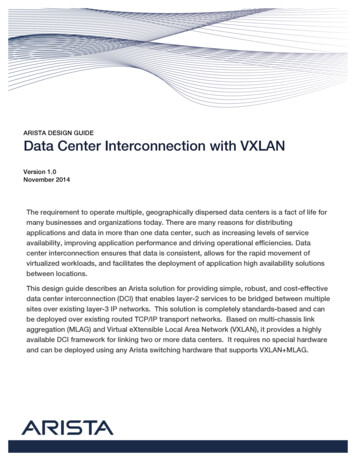
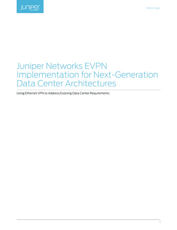
Design GuideThe Drivers For Data Center InterconnectionOperating multiple, geographically dispersed data centers has been regarded as best practice for many years, and all types ofbusinesses and organizations use this deployment model. Today, it may even be a statutory requirement for some businesses (e.g.,banking and finance), or a part of an organization’s governance policy.The original reason for building and operating multiple data centers was to ensure business continuity. The rationale was simple: itwas highly unlikely that an issue affecting power or service provision in one part of the world would also impact another location(provided they are adequately far apart). A beneficial side-effect of dispersing applications and data was that they could bepositioned close to the ultimate consumers of the service, which in turn meant users experienced better response times, resulting inimproved productivity (or in the case of customers, greater satisfaction with the service). The consequence of locating services closeto users was that there was less demand for bandwidth on expensive wide-area connections, thus reducing operational costs.With the dispersion of applications and data came the need to ensure consistency of information between locations. This has driventhe need to interconnect data center locations for the purposes of data replication and to enable shared information processingbetween servers forming geographically dispersed clusters.More recently, additional drivers for data center interconnection (DCI) have emerged. The widespread use of server virtualizationhas delivered the potential to provide live migration of compute workloads (e.g., applications, virtual desktops, etc.) between sites.The original reason to provide the live migration of workloads was for improved service availability. However, this ability to moveworkloads between locations has given rise to other use cases; for example, applications can be moved to locations to be close toservice users (e.g., “follow-thesun”) or to where power is cheaper (e.g., “follow-the-moon”).Figure 1: Some of the Typical Use Cases for Data Center InterconnectionWith the advent of cloud computing models for IT service delivery, the dynamic provisioning of workloads, and the capability toinstantiate applications on demand (often without consideration of location), the possibility that the constituent elements of anapplication could be split across different data centers becomes a reality. Likewise, cloud solutions may choose to “re-balance” aworkload based on specific operational criteria. For example, virtual machines (VM) may be automatically moved from a serverrequiring downtime for maintenance, or workloads may be redistributed across physical hosts in order to optimize powerdistribution or cooling. It is quite possible that VMs could be placed on physical servers in different data centers.arista.com3
Design GuideWith the advent of cloud computing models for IT service delivery, the dynamic provisioning of workloads, and the capability toinstantiate applications on demand (often without consideration of location), the possibility that the constituent elements of anapplication could be split across different data centers becomes a reality. Likewise, cloud solutions may choose to “re-balance” aworkload based on specific operational criteria. For example, virtual machines (VM) may be automatically moved from a serverrequiring downtime for maintenance, or workloads may be redistributed across physical hosts in order to optimize powerdistribution or cooling. It is quite possible that VMs could be placed on physical servers in different data centers.Data center interconnection is often required as a temporary measure to facilitate the permanent migration of applications anddata from one location to another. For example, many organizations are seeking to consolidate and rationalize their data centersin order to improve efficiency and reduce operating costs. In this case, a temporary DCI solution can be deployed to transfer dataand applications from a site due for closure to their new home. Migration can also be a requirement when businesses merge or areacquired, where the need to rationalize resources and locations is deemed necessary. The reverse scenario is also true, as in the caseof a business divesting part of its operation, where IT services need to relocate to the new organization’s facilities.Ultimately there are many circumstances driving need for data center interconnection and, in reality, businesses may have acombination of the requirements described above. It is likely that new requirements will emerge in the future, especially as adoptionof the cloud computing paradigm continues. In the next section we will consider some of the technical requirements for delivering aDCI solution.Data Center Interconnect TechnologiesMost network designers would prefer that data center interconnection over wide area networks (WAN) be performed at layer 3,without layer-2 connectivity spanning data centers. However, application requirements often make it necessary to provide layer-2interconnection between data centers, with common IP subnets and VLANs stretched across sites. While it is true that some VMmobility solutions have removed the need to provide layer-2 connectivity between locations, many current solutions still requirelayer-2 interconnection. This is also true of many high availability clustering systems and storage virtualization and replicationsolutions, which mandate layer-2 adjacency between physical nodes.However, native, long-distance, layer-2 connections such as local area network (LAN) extension services can be extremely difficultto find, especially outside of metropolitan areas or at distances that ensure data centers are adequately geographically dispersedto provide full protection from outages. Even where native layer-2 services are available, it may be undesirable to use them duepotential “fate-sharing” between sites, as in the case of a layer-2 problem such as a broadcast storm on one site impacting the otherdata center.Pseudowire & Tunelling SolutionsThe challenges associated with providing cost-effective, long-distance layer-2 interconnection led to the development of a set ofsolutions based on tunneling mechanisms. These were designed to allow layer-2 traffic to be transported over Layer-3 networks.Originally these solutions centered on the concept of a “pseudowire,” which allowed for the emulation of point-to-point Ethernetlinks by tunneling all traffic over wide area networks. Tunneling mechanisms such as Generic Router Encapsulation (GRE), Layer-2Tunneling Protocol (L2TP), or Multi Protocol Label Switching (MPLS), provided the underlying framework for this approach.Unfortunately, the initial solutions that emerged in this space, such as EoGRE (Ethernet over GRE), EoMPLS (Ethernet over MPLS),AToM (Any Transport over MPLS) did not scale well. For example, to allow any-to-any communication across multiple sites, fullmesh connectivity of point-to-point tunnels links was required. As a result, they proved difficult to deploy and very complex totroubleshoot. Also, due the unfiltered transmission of all traffic, these solutions did not deliver the necessary level of fault isolationbetween locations.In order to overcome some of the limitations of the point-to-point tunneling approach described above, technologies such asVirtual Private LAN Service (VPLS) were developed to allow the multipoint emulation of LAN services over underlying pseudowires.While this solution addressed some of the challenges associated with earlier approaches, in that it allowed multipoint connectivityand offered improved fault isolation between sites, it added the complexity associated with the underlying MPLS infrastructurenecessary to support it.arista.com4
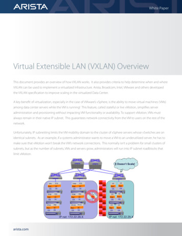
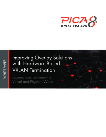
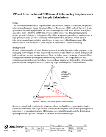
Design GuideIn recent years, much of the industry effort to find a simple, robust, multipoint mechanism for carrying layer-2 traffic over layer-3networks has polarized into distinct camps, with very little cross-vendor support. These solutions, which include OTV (OverlayTransport Virtualization) from Cisco, and Juniper’s EVPN (Ethernet Virtual Private Network), have aimed to address customerrequirements for DCI solutions, but have lacked any widespread support from other vendors, essentially locking customers into asingle supplier for their inter-datacenter connectivity. Even within the individual vendors, support for their respective solutions canbe very limited, often restricted to high-end and costly devices; for example, Cisco’s OTV is only available on the Nexus 7000 platformwith M-series modules and the ASR 1000 router.VXLAN: A Scalable, Standards-Based DCI SolutionGiven a blank sheet of paper it would not be difficult to define the desirable characteristics of layer-2-capable data centerinterconnect solutions. Ideally, any modern DCI solutions should meet the following basic criteria: Transparent to applications Transport agnostic – can operate over any IP-based service Multiple path and multiple site support Capable of providing fault isolation between data centers Interoperable and standards based Simple to implement Platform independent – no need for specialized hardware or equipment Managed and controlled as part of the wider DC infrastructure – not an “alien” technologyThe foundation of the Arista solution is Virtual eXtensible Local Area Network (VXLAN), an open IETF specification designed tostandardize an overlay encapsulation protocol, capable of relaying layer-2 traffic over IP networks. VXLAN has wide industry supportand was authored by Arista, Cisco and VMware with support from Broadcom, Citrix and Red Hat among others.Arista’s solution for data center interconnect meets these requirements and represents the industry’s first truly open standardsbased, simple to deploy and manage DCI system. It is cost-effective, running on standard switching hardware, and it provides activeactive switch redundancy and can interoperate with wide range of other data center switches, including those from other vendors.Introducing The Arista Networks DCI With VXLAN SolutionVXLAN was designed for the creation of logical layer-2 domains on top of an underlying IP network, initially to enable networkvirtualization in the data center. VXLAN identifies individual layer-2 domains using a 24-bit virtual network identifier (VNI), allowingfor up to 16 million independent domains to be specified. layer-2 Ethernet frames are encapsulated in IP UDP datagrams and arerelayed transparently over the IP network. It is the inherent ability to relay unmodified layer-2 traffic transparently over any IPnetwork that makes VXLAN an ideal technology for data center interconnection.Within the VXLAN architecture, virtual tunnel end points (VTEP) perform the encapsulation and de-encapsulation of layer-2 traffic.Each VTEP is identified by an IP address, which is assigned to a virtual tunnel interface (VTI). The VTEP receives standard layer-2Ethernet frames, selects the correct VNI and forms an IP UDP packet for transmission to one or more destination VTEPs. The source IPaddress is that of the sending VTI; the destination IP address is that of the receiving VTI.The VNI is typically determined based on the IEEE 802.1Q VLAN tag of the frame received. The destination VTEP (or VTEPs in the caseof multicast or broadcast traffic) is selected using a destination-to-VTEP map. This map is very similar to the MAC bridging table,except MAC addresses are associated with IP addresses rather than switch interfaces.arista.com5
Design GuideFigure 2: VXLAN Components and OperationMAC Learning And The Forwarding Of Broadcast & Multicast TrafficIn order to transparently support layer-2 traffic, each VTEP must handle the forwarding of broadcast and multicast traffic as well asensure previously “unseen” MAC addresses and their “locations” are learned. In a layer-2 network, MAC address learning is performedby flooding frames with unknown unicast addresses on all ports within a given VLAN. For VXLAN, the approach specified in the IETFRFC is based on IP multicast. In this scenario, one or more IP multicast groups are set up to carry unknown unicast broadcast andmulticast traffic to VTEPs associated with a given VNI.This approach means that the underlying IP network used to transport VXLAN encapsulated traffic must support IP multicast.However, many wide area networks used to interconnect data centers do not support or implement IP multicast. To alleviate thisissue, Arista has introduced a feature referred to as “Head End Replication” (HER), which takes incoming broadcast, multicast, andunknown unicast traffic and sends a single unicast copy to each of the VTEPs receiving traffic for a given VNI.Arista DCI Solution ComponentsThe foundation of the Arista solution for data center interconnection is the VXLAN Hardware Gateway, deployed in conjunction withmulti-chassis link aggregation (MLAG).In addition, Arista’s Virtual ARP (vARP) mechanism can be used to ensure redundant first-hop router interfaces are localized withinthe data center, in order to prevent traffic destined to exit the data center from consuming bandwidth on the links interconnectingdata centers.arista.com6
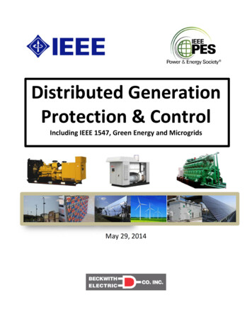
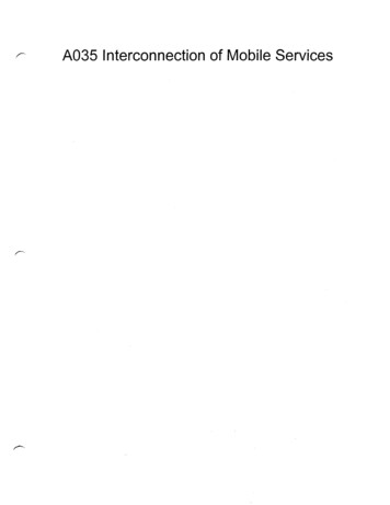
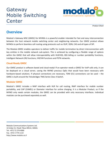
Design GuideArista Networks VXLAN Hardware VTEP GatewayFigure 3: Arista Hardware VXLAN Gateway ArchitectureConfiguring the Arista VXLAN Hardware Gateway is extremely simple. An IP address for each VTEP is specified using a loopbackinterface, which is in turn mapped to the VTI (referred to as the “vxlan 1” interface). The default IP port for VXLAN traffic is UDP 4789,although this can be changed if required.Each VTEP performs local-VLAN-to-VXLAN-VNI mapping, enabling VLAN translation to be performed as part of the tunneling processif required (i.e., source and destination VLAN IDs can be different). The Arista VXLAN Hardware Gateway is capable of emulatinglayer-2 local area networks (LANs), so both point-to-point and point-to-multi-point logical layer-2 topologies are supported with theability to deliver broadcast, multicast and unknown unicast traffic. Each VTEP filters spanning tree BPDUs ensuring that each DC is anindependent spanning tree domain, helping isolate potential faults.The initial version of Arista’s VXLAN gateway handled the flooding of broadcast, multicast and unknown unicast traffic using a single,configurable multicast group. Later versions of Arista EOS introduced the option to use Head End Replication (HER), which allowstraffic with multiple destinations (i.e., broadcast or multicast frames) or traffic requiring flooding (i.e., unknown unicast frames) to berelayed in individual IP unicast packets, thus eliminating the need to implement multicast on the layer-3 transport network.arista.com7
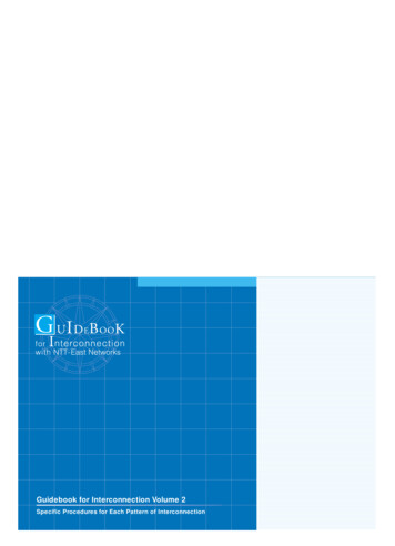
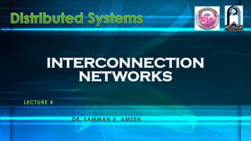
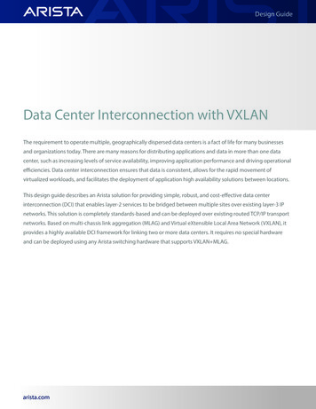
Design GuideFigure 4: Arista VXLAN Point-to-Point & Multipoint VNIs with VLAN TranslationLicensing & Platform SupportVXLAN requires the Arista V- Virtualization Features License. Full details of VXLAN feature availability and platform support can befound at: sArista Multi-Chassis Link Aggregation (MLAG)Arista’s multi-chassis link aggregation (MLAG) enables ports on two separate switches to be combined into a single Ethernet portchannel. For example, two 10-gigabit Ethernet ports, one each from two MLAG-configured switches, can connect to two 10-gigabitports on a host, switch, or network device to create a link that appears as a single 20-gigabit port channel. MLAG-configured portseffectively provide layer-2 multi-path forwarding, thus increasing bandwidth, providing higher availability and improving efficiencyby avoiding the need to have either active-standby connections or to rely on spanning tree to block alternate paths.With MLAG, two aggregation switches create a single logical layer-2 switching instance that utilizes all connections to the switches.Interfaces on both devices participate in a distributed port channel, enabling all active paths to carry data traffic while maintainingthe integrity of the Spanning Tree topology.Arista MLAG provides these benefits: Provides higher bandwidth links as network traffic increases. Utilizes bandwidth more efficiently with fewer uplinks blocked by STP. Connects to other switches and servers by static LAG or IEEE 802.3AX Link Aggregation Control Protocol (LACP) without theneed for proprietary protocols. Aggregates up to 32 10-Gbps Ethernet ports across two switches: 16 ports from each switch. Supports normal Spanning Tree Protocol (STP) operation to prevent loops. Supports active-active layer-2 redundancy.arista.com8
Design GuideAn MLAG consists of two or more links that terminate on two cooperating switches and appear as an ordinary link aggregationgroup (LAG) to the connecting device (e.g., switch, host, storage system, load-balancer, firewall etc.). The two switches that form theMLAG relationship are referred to as MLAG peer switches, which communicate through an interface called a MLAG Peer Link. Whilethe Peer Link’s primary purpose is exchanging MLAG control information between peer switches, it also carries data traffic fromdevices that are attached to only one MLAG peer and have no alternative path. An MLAG domain consists of the peer switches andthe control links that connect the switches.A dedicated MLAG peer VLAN is configured on each of the peers to maintain the peer link and relay control information using TCP.An IP address is assigned to the peer VLAN interface on each switch.The MLAG domain ID is a text string configured in each peer switch. MLAG switches use this string to identify their respective peers.The MLAG system ID (MSI) is the MLAG domain’s MAC address. The MSI is automatically derived when the MLAG forms and does notmatch the bridge MAC address of either peer. Each peer uses the MSI in STP and LACP PDUs.The topology in Figure 5 contains two MLAGs: one MLAG connects each device to the MLAG domain. Each peer switch connects tothe two servers through MLAG link interfaces. In this example, the MLAG for Host A contains two links, while the MLAG for Host B has4 links. Switch A and Switch B are peer switches in the MLAG domain “MLAGDomain01” and connect to each other through the peerlink.Figure 5: Arista Multi-Chassis Link Aggregation ArchitectureIn a conventional topology, where dual-attached devices connect to multiple layer-2 switches for redundancy, Spanning TreeProtocol (STP) blocks half of the switch-device links. In the MLAG topology, STP does not block any portion because it views theMLAG Domain as a single switch and each MLAG as a single link. The MLAG protocol facilitates the balancing of device trafficbetween the peer switches.When MLAG is disabled, peer switches revert to their independent state. MLAG is automatically disabled by any of the followingconditions: The MLAG configuration is changed The TCP connection between MLAG peers fails The peer link or local interface goes down A switch does not receive a response to a keep-alive message from its peer within a specified periodarista.com9
Design GuideAs Arista MLAG is standards-based, two MLAG domains can be connected together to form a “bow-tie” topology as shown in Figure6. It is also possible to connect other vendors’ implementation of multi-chassis link aggregation to an Arista MLAG pair in the sameway, provided the links conform to either the IEEE 802.1AX LACP specification or can be configured as a static LAG.Figure 6: “Bow-Tie” MLAG TopologyArista VXLAN MLAG SolutionArista’s implementation of VXLAN can span a pair of switches interconnected with MLAG. This allows for the implementation of aVTEP that operates on two separate switches simultaneously, effectively creating a “logical” VTEP. This doubles performance as wellas providing an active-active, fully redundant highly available system.Figure 7: Arista VXLAN MLAG Hardware VTEP Architecturearista.com10
Design GuideDeploying The Arista VXLAN DCI SolutionThere are a wide variety of topologies that can be supported with the Arista VXLAN Data Center Interconnect solution, includingdual-site or 3 or more site configurations. At each site, the DCI connection can be implemented as a highly available VXLAN MLAGconfiguration or as a single VXLAN-enabled switch. With EOS 4.14, Arista supports VXLAN MLAG bridging on the 7150 and 7280SEswitches. Standalone VXLAN bridging is also supported on the 7050X family of switches. The wide variety of Arista platformssupporting VXLAN bridging in hardware allows users to select the best product for the any given deployment scenario. For example,smaller locations can utilize the cost effective 7150S-24 24-port 10GbE switch, while larger sites with more demanding trafficworkloads can deploy the 7280SE-64 with 48 x 10GbE and 4 x 40GbE ports, which due to its 9GB of deep buffering would be a idealchoice. The 7280SE is especially suited for scenarios where the oversubscription ratio from LAN to WAN may be very high or wheretraffic profiles have significant but transient bursts.Figure 8: The Industry’s First Truly Flexible, Scalable, High-Performance and Cost-Effective DCI SolutionIntegrating The Arista DCI Solution With Existing NetworksAs VXLAN is standards-based, it is relatively simple to connect existing network equipment to the Arista VXLAN DCI solution. Anydevice capable of link aggregation or port channels —either statically configured or using 802.3AX Link Aggregation ControlProtocol (LACP) —can connect to the Arista switches as an MLAG pair. This includes, of course, other Arista devices, or other vendors’solutions such as Cisco VPC or VSS, or equivalent technologies from other vendors.The most common deployment scenario for the Arista VXLAN DCI solution a dual-site DC environment with active-activeVXLAN MLAG DCI configurations at each site. Typically the pair of VXLAN MLAG switches to be used for data center interconnectionare deployed as a dedicated “DCI module”, which is connected to the existing leaf-spine data center network (DCN) via a “networkedge leaf” using a “bow-tie” MLAG configuration (as shown in Figure 9). DC network edge leaf can consist of any switch capable ofsupporting standards-based single- or multi-chassis link aggregation, either using static port channels or IEEE 802.1AX-2008 LACPbased link aggregation. The inter-site connection can be a direct, point-to-point layer-3 link, or a routed transport network. Anydynamic routing protocol supported on the Arista switches can be used (e.g. OSPF, BGP, IS-IS etc.) or static routing can be used ifpreferred.arista.com11
Design GuideFigure 9: Integration of the DCI module with a Leaf-Spine Data Center NetworkArista’s leaf-spine architecture can be built with either a layer-2, MLAG-based spine or with a layer-3 routed spine. With a layer-2leaf-spine topology, VLANs can be extended from any leaf node to the Arista DCI module. In the case of a layer-3 leaf-spine topology,layer-2 network virtualization with VXLAN and Arista’s hardware VTEP allows VLANs to span different leaf blocks, allowing VLANs tobe extended to the DCI module as required.Of course, not all data center networks are built using leaf-spine architectures and there are still many DC networks in operationtoday based on hierarchical 3-tier designs. These 3-tier designs are often built with layer-2 access and distribution tiers, and withlayer-3 interfaces in the core tier. The core provides inter-VLAN routing as well as access to external WAN routers and infrastructureservices such as firewalls, load balancers, etc. In this scenario, the logical place to connect the Arista DCI module is to the coreswitches, with the inter-DC interfaces on the Arista switches either routed via existing external routers or dedicated DCI routers,or routed directly to the corresponding Arista DCI switches at the remote site. In this scenario, servers, storage etc. have layer-2connectivity to the Arista DCI module.The VLANs that are identified as needing to be relayed between data centers are trunked via the MLAG to the DCI module switches.Within the DCI modules, these VLANs are mapped, one-to-one, to VXLAN VNIs, and the remote VTEPs are configured for each VNI tobe carried for the purposes of Head End Replication. A logical VXLAN VTEP that spans both MLAG member switches is configured oneach of the DCI modules. Logical VTEPs are configured in the exact same way as those on standalone switches, with each member ofthe logical VTEP being configured with the same VTI address.Depending on the specific deployment scenario, careful consideration will need to be given to the intervening transportnetwork, especially with respect to the maximum transfer unit (MTU) size. As VXLAN is a MAC-in-IP encapsulation technology,the encapsulation process will add 50 additional bytes to each frame being relayed across a VXLAN connection. Networkingdevices carrying VXLAN-encapsulated traffic, both within the DC and across the wide area network transport, need to be capableof supporting the resulting larger packets. If, as in some cases, some older router interfaces are incapable of supporting MTUs ofgreater than 1500 bytes, it may be necessary to modify the default MTU size on some end devices to ensure this limit isn’t exceeded.arista.com12
Design GuideConfiguration ExampleThe following example describes a simple VXLAN data center interconnection deployment scenario, with the followingcharacteristics: Dual data centers A DCI module per site, consisting of a pair of switches configured as an MLAG pair connected to a single LAG attached to a“downstream” switch (representing the local DC network) Parallel, point-to-point layer-3 links between adjacent MLAG members at each DC A logical VXLAN VTEP configured on each DCI MLAG pair OSPF routing between sites ››Two VLANs (100 & 200) to relay between sites, each mapped to a corresponding VXLAN VNI as follows:››VLAN100 mapped to VNI 10000VLAN200 mapped to VNI 200The following diagrams show, in turn, the physical and logical topologies of this network. The relevant configuration file sections arealso included for reference.The Physical TopologyFigure 10 shows the physical topology used for this configuration example. All links are 10GbE in this example.Figure 10: Example DCI Solution – Physical Topologyarista.com13
Design GuideSwitch Configuration - InterfacesThe following configuration examples show the non-default interface configuration required to build the above topology, i.e., Inter-site links configured as layer-3 routed interfaces MTU size adjusted on these interfaces, as the default for layer-3 interfaces is 1500 bytes (i.e., increase the MTU to the maximumof 9124 bytes)All other interfaces use default configuration.Figure 11: Example DCI Solution – Layer-3 InterfacesThe following configuration file sections show the relevant interface configuration for each of the DCI switches.Switch “dcia-s1”!interface Ethernet1description P2P L3 link to dcib-s1mtu 9214no switchportip address 172.16.0.1/30!Switch “dcia-s2”!interface Ethernet1description P2P L3 link to dcib-s2no switchportmtu 9214ip address 172.16.0.5/30!arista.com14
Design GuideSwitch “dcib-s1”!interface Ethernet1description P2P L3 link to dcia-s1no switchportmtu 9214ip address 172.16.0.2/30!Switch “dcib-s2”!interface Ethernet1description P2P L3 link to dcia-s2no switchportmtu 9214ip address 172.16.0.2/30!The MLAG TopologyFigure 12 shows the MLAG configuration and topology details used for this example configuration.Figure 12: Example DCI Solution – MLAG Topologyarista.com15
Design GuideSwitch Configurations - MLAGThe following configuration examples show the non-default configuration required to build the above topology, i.e., MLAG peer VLAN (i.e., VLAN 4094) created and assigned to the M
Design Guide Data Center Interconnection with VXLAN The requirement to operate multiple, geographically dispersed data centers is a fact of life for many businesses and organizations today. There are many reasons for distributing applications and data in more than one data . Cisco and VMware with support from Broadcom, Citrix and Red Hat .