Transcription
DECEMBER 2008 ICE STORMAppendix F - Overhead Line ConstructionAPPENDIX FOverhead Line ConstructionA. LINE CONSTRUCTION AND LOADINGPrevailing laws and practice in most states in the United States require overhead lines bedesigned, at the very minimum, to meet the National Electrical Safety Code (NESC). 1 NewHampshire Code of Administrative Rules Puc. 306.01 mandates that New Hampshire utilitiesmust use the requirements of the NESC to construct their facilities in accordance with goodutility practice. In addition, some states, such as California, have adopted by law their owncodes which often refer to NESC requirements. 2 In the United States, most structures (other thantransmission and distribution lines) are built according to the International Building Code (IBC),which often defaults to American Society of Civil Engineers (ASCE) standards on such issues asloading and methods. Current practice is to design structures using two well accepted designmethods. The first and oldest is the “Allowable Stress Design” (ASD) method, and the second is“Load and Resistance Factor Design” (LRFD), which is the method most commonly taught incolleges and toward which the industry appears to be moving.The NESC, however, uses neither of these commonly accepted methods. Instead, it historicallyhas used an ultimate stress design method with overload factors used in the loading part of thedesign to provide the needed factors of safety. This method differs from all other commonlyaccepted design methods. Loading requirements contained in the NESC are different than thoseused in any other code. NESC rules for selection of design loads and for safety factors arelargely based on successful experience, but have little basis in theory. 3 The more modernmethods of design, such as LRFD, have been developed using successful experience as well asstructural theory that has become accepted over the years. As a result, the 2007 edition of theNESC contains sections which have begun to include LRFD methodology such as is commonlyaccepted for other types of construction. It should be noted that the NESC still includes the olderhistorical methods alongside the newer methods and appears to be in a process of transition.However, at this time the requirements of the NESC do not closely match the requirements thatan engineer would be obliged to use when designing a habitable structure.In many cases a power line design produced by strictly following the NESC loading and designcriteria will deliver a less capable structure with lower factors of safety than would be produced1Dagher, H.J. “Reliability of Poles in NESC Grade C Construction.” IEEE Rural Electric Power Conference 2001,Pgs C4/1-C4/6. (10.1109/REPCON.2001.949521).2State of California General Order 95. (January 2006). Rules for Overhead Electric Line Construction.3Bingel, N., Dagher, H., et.al. (2003). “Structural Reliability-Based Design of Utility Poles and the NationalElectrical Safety Code.” Transmission and Distribution Conference and Exposition 2003, Vol. 3.Pgs 1088-1093.(10.1109/TDC.2003.1335100).NEI Electric Power EngineeringPage F-1
DECEMBER 2008 ICE STORMAppendix F - Overhead Line Constructionif the structure were designed using methods required for other types of structures, such as thethose required by the (IBC). 4 There is disparity between the results produced by building underthe NESC instead of the IBC. The NESC tries to simplify things for the designer by specifyingloading requirements that have been developed for average conditions over a large part of thecountry, while other codes use more exact data specific for small areas. Problems occur whenlocal conditions vary from those considered average by the NESC. An area with high likelihoodof large amounts of wind and ice, such as most of New Hampshire, will see more damage thanaverage. Conversely, an area with lower expectations of wind and ice will see less than averagedamage on their system. Questions have also emerged as to the reliability of the NESC loadingcriteria with the development of joint use poles. Loading criteria and design methodology usedin the NESC may not adequately anticipate the additional use of the utility's poles by a telephoneor cable company. 5 For this reason, many utilities have developed their own standards whichmore closely match local conditions. In most cases, these standards produce a more robust andrealistic design for an area than simply using the criteria in the NESC. In New Hampshire, allfour major electric utilities use NESC loading. Only Public Service of New Hampshire uses anadditional standard which exceeds NESC requirements for some transmission lines. It must benoted, however, that many utilities across the country have used NESC loading criteriaexclusively over the years and have had good success. This is likely due to the fact that theaverage loading shown in NESC for their region closely matches or exceeds the actual conditionswitnessed in their exact location.The NESC recognizes three grades of construction which may be used in different areas: N, C,and B. 6 Grade N is the lowest strength, has the lightest loading requirements, and the smallestsafety factors. Using Grade B construction results in the highest strength and largest safetyfactors. This results in the heaviest and most costly construction. Grade N may be used foremergency or temporary construction, on private right-of ways below 8.7kV, and forcommunication cables or cables below 750V. None of the four utilities in New Hampshirepresently allow grade N construction on their systems. The NESC allows grade C constructionin most other areas except at line, railroad. or limited access crossings where grade B is required.The grade of construction used is based upon the degree of importance and reliability levelneeded for the line. 7 Lines that are less important may be allowed to be constructed with a lowergrade of construction, which has a lower factor of safety and may be expected to suffer morefailures during an extreme weather event. For example, a rural single phase line crossing an4Malmedal, K. and Sen, P.K. (2003).”Structural Loading Calculations of Wood Transmission Structures.” IEEERural Electric Power Conference 2003.Pgs A3/1 – A3/8.5Bingel, N., Dagher, H., et.al. (2003). “Structural Reliability-Based Design of Utility Poles and the NationalElectrical Safety Code.” Transmission and Distribution Conference and Exposition 2003, Vol. 3.Pgs 1088-1093.(10.1109/TDC.2003.1335100).6National Electrical Safety Code. (2007). ANSI/IEEE C2-2007.7Bingel, N., Dagher, H., et.al. (2003). “Structural Reliability-Based Design of Utility Poles and the NationalElectrical Safety Code.” Transmission and Distribution Conference and Exposition 2003, Vol. 3.Pgs 1088-1093.(10.1109/TDC.2003.1335100).NEI Electric Power EngineeringPage F-2
DECEMBER 2008 ICE STORMAppendix F - Overhead Line Constructionopen pasture to a stock water tank may be constructed as grade N, especially if privately owned.The failure of this line during a storm might pose an inconvenience but would not normally posea direct threat to human life. On the other hand, a line crossing an interstate highway or railroadcould cause disastrous results if it failed and dropped onto an automobile or train. Additionally,the repair of this line without closing the highway or rail line would be very difficult. For thisreason, a line of this type must be built to grade B construction, which has the highest factor ofsafety of all the grades of construction.Another design guide commonly used in the United States is the RUS Bulletin 1724E-200,Design Manual for High Voltage Transmission Lines. The specifications in this guide arerequired for all Rural Electric Co-ops (REC) which borrow funds from the Rural Utility Service(RUS, formerly known as REA). This manual requires Grade B construction for lines 35kV andover while accepting the NESC requirements for other voltage classes and definitions forconstruction grades. It also has more conservative loading requirement than the minimumrequired by the NESC. Following this guide will generally produce a more robust design withhigher safety factors than those that will occur when using only the NESC. 8 RUS guidelines alsorecognize that NESC minimum construction may be inadequate for local conditions and thatlocal requirements may supersede those contained on the NESC or RUS documents. 9There are other design manuals which are commonly used by designers when deciding how todetermine loads and design criteria for overhead transmission and distribution lines. While notreaching the level of model codes or having the weight of either the NESC or RUS documents,they provide guidance that can be referred to and valuable information for the designer. The firstis ASCE Manual and Report on Engineering Practice No. 74: Guidelines for ElectricalTransmission Line Structural Loading. This manual supplies some of the theoretical basis forthe methods suggested for determining wind, ice, and other types of loading. and providesexamples that can be referred to in designing overhead line structures. It also providessuggestions for load and strength multiplying factors for various conditions and materials, anddescribes the probabilistic approach used to determine these factors. This manual is independentof the requirements in the NESC. It is based upon theory and loading data rather than using thelegacy methods required by the NESC. This manual is presently being revised, as some of theinformation included in it is now considered outdated and is being replaced by the informationcontained in ASCE Standard 7-05.ASCE Standard 7-05: Minimum Design Loads for Buildings and Other Structures is also of greatvalue in determining loads to place on overhead lines. This manual contains the most up-to-dateinformation available regarding maximum wind speeds and ice loads for each part of the8U.S. Department of Agriculture, Rural Utility Service. (2004). Design Manual for High Voltage TransmissionLines. (RUS Bulletin 1724E0200)9U.S. Department of Agriculture, Rural Electrification Administration. (1982). Mechanical Design Manual forOverhead Distribution Lines. (REA Bulletin 160-2).NEI Electric Power EngineeringPage F-3
DECEMBER 2008 ICE STORMAppendix F - Overhead Line Constructioncountry. It divides the country into much smaller areas than are shown in the NESC districtloading maps. The provisions and methods included in ASCE 7-05 are also required whenstructures are designed using the International Building Code. The ice loading informationcontained in ASCE 7-05 is prepared, compiled, and updated by the U.S. Army Corps ofEngineers Cold Regions Research and Engineering Laboratory (CRREL) located in Hanover,NH. This manual contains historical maximum weather loading information compiled from datacollected by the laboratory. It is more up-to-date and provides more realistic weather loadingdata than that contained in the NESC. It is interesting to note that the 2007 NESC has for thefirst time included extreme wind maps and concurrent wind and ice loading maps which arederived directly from ASCE 7-05, yet the NESC does not require using either extreme wind orextreme ice with concurrent wind until a structure is taller than 60 ft. This is in contrast to boththe ASCE and RUS documents that suggest including these two loading cases in all designs. Allstructural codes presently used in the United States have either already adopted or are movingtoward the loading and weather criteria contained in ASCE 7-05. This can be expected tocontinue into the future.Another manual which explains the statistically derived loading and strength methods includedin ASCE design manuals is ASCE Manuals and Reports on Engineering Practice No. 111:Reliability-Based Design of Utility Pole Structures. This manual explains and gives examples ofthe methods described in the ASCE codes use for determining load factors and strength factors.Every line should be designed for reliability, security, and safety. Security is the ability of adesign to prevent the propagation of an initial failure to additional failures; safety meansprotecting the public at all times and construction personnel during construction andmaintenance; reliability is the ability of the line to resist without damage a climatic event with acertain return duration, such as designing a line with the ability to stand up to a storm withoutdamage with a recurrence of 50 years, which is the most commonly used return period foroverhead line construction. 10 These objectives are normally accomplished by assuming a designload equal to the maximum ice and wind load which can be expected to occur during the servicelife of the line. This value is then multiplied by a factor of safety to make sure that the weakeststructure in the design can resist the expected loads even after some deterioration due to age andaccounting for the variations in material tolerances, which can be large in the case of wood andsomewhat less in designed materials such as steel and composites. The two most importantclimatic conditions of interest in New Hampshire are the amount of ice that can be expected toaccumulate on a line, usually stated as radial thickness of ice, and the wind pressure on the linewhich is a function of wind speed, height, and terrain type. The line should be designed for threeload types: The maximum wind pressure the line will be expected to see during its lifetime, themaximum ice load the line will be expected to see, and the combination of the maximum amount10Peyrot, A., Maamouri, M., et al. (1991). “Reliability-Based Design of Transmission Lines: A Comparison of theASCE and IEC Methods.” The International Conference on Probabilistic Methods Applied to Electric PowerSystems, 1991. Pgs 97-102.NEI Electric Power EngineeringPage F-4
DECEMBER 2008 ICE STORMAppendix F - Overhead Line Constructionof ice the line will see in combination with the amount of wind pressure that can be expectedduring this icing event. The way this information is derived varies depending upon the code thedesigner decides to use.After deciding the level of loads to be placed on the line, the designer must next decide upon thesafety factors which must be applied. These safety factors vary with types of material. Naturallyoccurring materials (such as wood) require larger safety factors than engineered materials (suchas steel). This is due to the fact that there is a larger variation in strength based on the material.For example, tolerances between the strongest and weakest wood members will vary a muchgreater degree than those between the strongest and weakest steel or concrete members. Thedesigner will design around some average value of strength of the material and the safety factorswill account for the variations around these average values to try to ensure that even the weakeststructures will not fail under the design conditions. The combination load and strength safetyfactors for steel structures may be up to 2.5, whereas the safety factors for wood could be aslarge as 4.0. Safety factors will also account for the unpredictability of characterizing the loads.Weather loads may be difficult to foresee and the safety factor accounts for this unpredictability.In the most modern method of design, load and resistance factor design, these factors of safetyare added by multiplying the loads by a load factor to account for the uncertainty in the loadinginformation, and then multiplying the strength of the material by a strength factor to account forthe variation in material strengths. The latest version of the NESC has also begun to take thisapproach.In order to optimize the design of an overhead line, loadings must be chosen correctly. This isnot easy in practice, especially where ice loading is concerned. Several types of icing may occuron an overhead line depending upon the conditions occurring at the time. Some of these are: Glaze ice: Clear ice possibly with icicles, very denseHard Rime Ice: Opaque milky to nearly transparent, may be alternate layers of clear andopaque ice, intermediate density to very denseSoft Rime Ice: White, granular, snow-like, weak and low densityHoar Frost: White snow-like, irregular crystalline deposits, very brittle and low densitySnow and sleet: Can melt and re-freeze several times and attain large weightsIcing can occur in cloud during fog or during precipitation. 11 The type and amount of icing thatmay occur depends on air temperature, water droplet size, water content of the air, wind speed,and local topographic effects near the line. For this reason icing may be highly variable alongthe length of a line. Due to the high variability of icing, it is impractical to try to determine theexact type of ice that may occur along the entire length of a line. In the United States, theprotocol is to design the line for an equivalent radial ice load. This load is normally found from11Ervic, M., Fikke, S.M. (1982). “Development of a Mathematical Model to Estimate Ice Loading on TransmissionLines by Use of General Climatological Data.” IEEE Transactions of Power Apparatus and Systems, June 1982.Pgs1497-1503. (10.1109/TPAS.1982.317197).NEI Electric Power EngineeringPage F-5
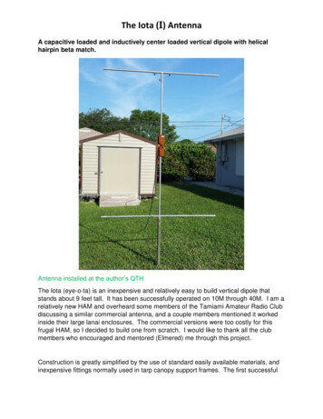
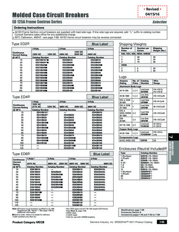
DECEMBER 2008 ICE STORMAppendix F - Overhead Line Constructionmaps prepared by various groups using both actual historical measurements and theoreticalstatistical methods. 12 These maps are developed using algorithms developed from research doneby groups such as CRREL.In some areas of the country, the loading described by the NESC and for which most overheadlines are designed (including those in New Hampshire) varies considerably from the loadingdescribed in other documents published by ASCE and other sources. 13 14 The NESC should beconsidered the minimum mandatory requirement for loading and design. As utilities oftenrecognize, the NESC merely describes conditions that can be expected to occur frequently ratherthan providing information about the maximum wind or ice that may be expected with a 50 yearor 100 year recurrence.Extreme weather events are described as random variables in probability distributions. Thedesigner must decide on how rare of an event they are willing to design their systems towithstand. The designer of a building which may be expected to have a service life of 100 yearsor more might design for the largest weather event that may be expected to occur in 100 years.For the power line designer, the expected lifetime of their design is customarily 50 years.Therefore, the designer will design for the weather conditions that may be expected to occur onlyonce every 50 years. The maps given in the NESC showing design loads typically show valuesof wind and ice which can be expected to occur once in any 50 year period. 15 The return period(RP) of the 2008 storm was 10 years, 12 which means that the magnitude of the storm was nothighly unusual. Any lines designed for a storm of a 50 year return period should have weatheredthe impact of this storm.In many areas the loading and safety factors in the NESC have produced reliable designs, whilein others areas the loading conditions shown in the NESC have proven to be inadequate for localconditions. Because of this fact, utilities often require a stricter minimum loading condition thanshown in the NESC, especially if local ice and wind loading data are available and conflict withthose shown in the NESC.Figure F-1 shows the loading criteria required by the NESC. There are only three loadingconditions, or districts, defined: light, medium, and heavy loading. 16 These loading districtsdefine both wind and ice loads to be used for structures below 60 ft. in height, and for these12Jones, K.F., Cold Regions Research and Engineering Laboratory (July 2009). The December 2008 Ice Strom inNew Hampshire.13Minimum Design Loads for Buildings and Other Structures. (2005). American Society of Civil Engineers 2005.(ASCE Standard 7-05).14Guidelines for Electrical Transmission Line Structural Loading. (1991). American Society of Civil Engineers1991. ASCE Manuals and Reports on Engineering Practice No. 74.15Reliability-Based Design of Utility Pole Structures. (2006). American Society of Civil Engineers 2006. ASCEManual and Reports on Engineering Practice No. 111.16National Electrical Safety Code. (2007). ANSI/IEEE C2-2007.NEI Electric Power EngineeringPage F-6
DECEMBER 2008 ICE STORMAppendix F - Overhead Line Constructionstructures, which would include most distribution lines, this is the only loading case required bythe NESC. The loads defined for the three districts are: Heavy: 0.5 in. ice and 4 psf. of wind (equivalent to a 40 MPH wind) 17Medium 0.25 in. of ice and 4 psf. of wind (equivalent to a 40MPH wind)13Light 0.0 in. of ice and 9 psf. of wind (equivalent to a 60 MPH wind)13Figure F-1 - NESC loading map.It may be seen that each of the three loading areas shown in Figure F-1 are quite large. Smallvariations due to terrain and even geographic location do not affect the loading levels shown inthis map. The ice and wind load for New Hampshire, for example, is shown to be exactly thesame as that for eastern Colorado, when in reality both icing and wind conditions for NewHampshire are far more severe than they are for eastern Colorado.If a structure is taller than 60 ft. (which would primarily include transmission structures), theNESC requires that two other loading conditions be examined: extreme wind and extreme ice17Bingel, N., Dagher, H., et.al. (2003). “Structural Reliability-Based Design of Utility Poles and the NationalElectrical Safety Code.” Transmission and Distribution Conference and Exposition 2003, Vol. 3.Pgs 1088-1093.(10.1109/TDC.2003.1335100).NEI Electric Power EngineeringPage F-7
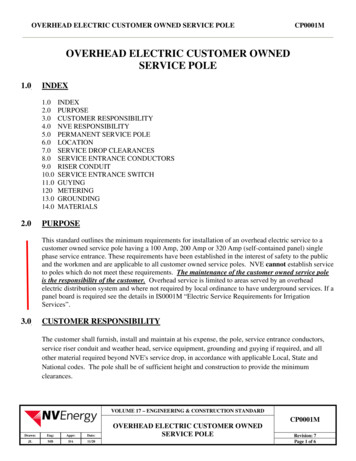
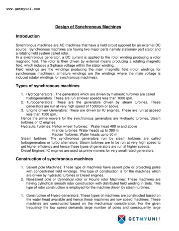
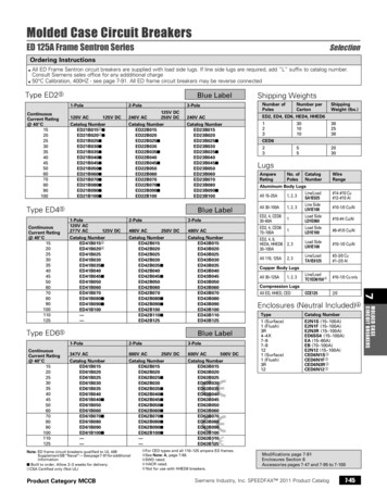
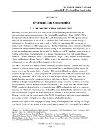
DECEMBER 2008 ICE STORMAppendix F - Overhead Line Constructionwith concurrent wind. Figure F-2 shows the NESC map for extreme wind contained in theNESC. 18 It may be seen that a wind speed of 90 to 100 MPH is given for New Hampshire with aspecial wind area for the mountainous area along the New Hampshire and Vermont border. Aspecial wind area means that local wind information must be found and the speeds shown on themap cannot show adequate information for these areas. The wind values for these locations areusually determined from local building departments in cities within the special areas. Officialsin these cities have usually determined from experience the wind speeds required for safe designof buildings in their areas. The basic wind speeds shown in Figure F-2 are substantially higherthan those required by NESC heavy loading for New Hampshire, which would be the equivalentof a 40 MPH wind. The map in Figure F-2 is taken from the latest data included in ASCEstandard 7-05 while the loading in Figure F-1 has been included in the NESC without change formany years.Figure F-2 - Basic wind speed for extreme wind design.The third loading condition, extreme ice with concurrent wind, is considered by takinginformation from the map in Figure F-3. This map shows the 50-year return period levels for18National Electrical Safety Code. (2007). ANSI/IEEE C2-2007.NEI Electric Power EngineeringPage F-8
DECEMBER 2008 ICE STORMAppendix F - Overhead Line Constructionwind and ice for New Hampshire. It is also taken from the latest version of ASCE 7-05. 19 20 Asmay be seen in Figure F-3, the ice loading for New Hampshire varies from 0.75 in. with 40 MPHwind, to 1.0 in. with 40 MPH wind, and although not shown in the NESC map, the ASCE mapshows a special wind area shown along the Vermont-New Hampshire border. This wind and iceloading shown in Figure F-3 is greater than is required using only the district loading fromFigure F-1. For all structures designed using ASCE standards or the International BuildingCode, the loading shown in both Figure F-2 and Figure F-3 would have to be considered, but theNESC only requires these loads for structures above 60 ft. in height, which would not includemost distribution lines that only need to be designed for the loads shown in Figure F-1.Figure F-3 - Ice and concurrent wind for line design.It is generally recognized that the loading required in Figure F-1 has produced an adequatedesign on average when coupled with the safety factors (overload factors) contained in theNESC. For some areas with higher than average icing loads or higher than average wind loads,both of which would be true of New Hampshire, these levels of loading have produced designswith higher than average failure rates. In areas of lower than average wind and ice loads theselevels of loading have produced a more robust than necessary design. 21 No design approach isinherently more reliable than another; all design methods make assumptions about loading and19National Electrical Safety Code. (2007). ANSI/IEEE C2-2007.Minimum Design Loads for Buildings and Other Structures. (2005). American Society of Civil Engineers 2005.(ASCE Standard 7-05)21Bingel, N., Dagher, H., et.al. (2003). “Structural Reliability-Based Design of Utility Poles and the NationalElectrical Safety Code.” Transmission and Distribution Conference and Exposition 2003, Vol. 3, Pgs 1088-1093.(10.1109/TDC.2003.1335100).20NEI Electric Power EngineeringPage F-9
DECEMBER 2008 ICE STORMAppendix F - Overhead Line Constructionaccept some probability of failure. The art of good design is to reduce the probability of failurewhile at the same time minimizing the total lifetime cost. 22 If specific and accurate designcriteria is available for a region it becomes easier to produce a reliable design without spendingtoo much on overdesign. Overdesigning can occur when an engineer has insufficient loadingdata available making it impossible to accurately characterize the actual loads that will occur in acertain location. As a result the designer must compensate by using larger safety factors. In theattempt to make sure the structures are adequate the designer will likely produce an overly stoutdesign.The latest version of the NESC has endeavored to begin addressing the differences in reliabilitiesthat can be seen in lines built according the NESC district loading values from Figure F-1. It hasaddressed the differences apparent in various parts of the country, by revising the overloadfactors it uses. The overload factors used for overhead line design before the 2007 version of theNESC were historically derived and often based on subjective criteria including engineeringjudgment and experience.18 While the loading and methods historically used in the NESC haveproven successful over the years for most of the country, questions have arisen as to theirvalidity due to new methods and materials being used for line construction, including the use ofextensive numbers of shared-use poles by electric utilities and communications companies.There is some evidence that as communication under build (as used in the New Hampshiresystem) has become common, the loading criteria shown in the NESC has become less reliableover the years.The load and strength factors used in the 2007 version of the NESC are designed for use withboth NESC district loading and 50 year repeat period loading as shown in ASCE maps. Eventhough only NESC district loading cases are required for structures less than 60 ft., it isrecommended that the higher wind and ice loading cases required by ASCE data also be takeninto account for the design of all structures no matter their height. This should produce a morerealistic design for the conditions that can be expected in New Hampshire. Since the systemwould be designed for loads that can be expected to occur only once every 50 years, it should beeasily robust enough to sustain the loads imposed by a storm which can be expected to berepeated every 10 years, such as the one seen in 2008. This would include determining fromlocal sources the actual wind and ice loads which can be expected in the special wind areasshown on ASCE maps rather than relying on loading data from NESC maps.The question arises as to how the storm of December 2008 compares with the design criteriacontained in the NESC and in ASCE standards under which the lines in New Hampshire weredesigned. The first thing that must be understood is the levels of ice which occurred. The designvalues of ice and the values contained in the NESC tables are “equivalent radial glaze ice”values. These are not the same values as typically reported in the media or measured by weather22Sayer, B. (2000). “What of the Weather? Wood Pole Line Design & Weather Loadings.” IEE Seminar onImproved Reliability of Woodpole Overhead Line, (March 8). Pgs. 1/1-1/8.NEI Electric Power EngineeringPage F-10
DECEMBER 2008 ICE STORMAppendix F - Overhead Line Constructionstations. Forecasters and weather observers usually report ice accretion on a horizontal surfaceor on the ground. This might include the thickness of ice pellets and snow in addition to freezingrain. Occasionally the amounts of ice reported include icicles and the ice located on top ofbranches or wires. To determine the equivalent radial ice it would be necessary to take theaverage thickness of the same amount of moisture if it were spread evenly over the surface of aconductor. There is no method by which the ice accretions reported by weather stations can beaccurately converted to equivalent radial ice as needed for design and analysis of utilitystructures. 23To produce the maps contained in ASCE 7, and to determine equivalent radial ice for this storm,hourly weather data from weather stations is needed. This data must include wind, temperature,dew point, precipitation rate and type among other factors which are used in an ice accretionmodel developed by the New Hampshire Cold Regions Research and Engineering Laboratory(CREEL) to determine equivalent radial glaze ice values. These values may also be directlymeasured with freezing rain sensors if a weather station is so equipped. The exact methods usedare more complet
the NESC instead of the IBC. The NESC tries to simplify things for the designer by specifying loading requirements that have been developed for average conditions over a large part of the country, while other codes use more exact data specific for small areas. Problems occur when local conditions vary from those considered average by the NESC.