Transcription
White PaperJuniper Networks EVPNImplementation for Next-GenerationData Center ArchitecturesUsing Ethernet VPN to Address Evolving Data Center Requirements1
Juniper Networks EVPN Implementation for Next-Generation Data Center ArchitecturesWhite PaperTable of ContentsExecutive Summary. 3Introduction. 3Transforming the Data Center Network with VXLAN and EVPN. 3VXLAN Overview. 4Data Center Control Planes. 4EVPN Overview. 5EVPN Concepts. 6EVPN Remote MAC Learning.7EVPN Server Multihoming.7EVPN Fast Convergence. 10EVPN Broadcast, Unknown Unicast and Multicast (BUM) Traffic Overview.11EVPN BUM Traffic—Underlay Replication.12EVPN BUM Traffic—Ingress Replication.12EVPN Ingress Replication—Split Horizon and Designated Forwarders.13EVPN MAC Mobility. 16EVPN Distributed Default Gateways. 17EVPN and VXLAN Configuration. 18The Underlay. 18The Overlay .25EVPN and VXLAN Troubleshooting. 36Full Configurations. 50Conclusion.62About Juniper Networks.62List of FiguresFigure 1: Layer 2 logical networks. 3Figure 2: Application mobility across performance-optimized data centers (PODs). 4Figure 3: EVPN terminology. 6Figure 4: Remote learning (MAC/IP advertisement, EVPN Type 2 route).7Figure 5: EVPN Type 1 advertisement, ESI. 8Figure 6: EVPN Type 2 advertisement with associated ESI. 8Figure 7: Multipathing from LS1 to H2 via LS2 and LS3. 9Figure 8: Multipathing failure from LS1 to H2 via LS2 and LS3, without aliasing. 9Figure 9: Multipathing from LS1 to H2 via LS2 and LS3, with aliasing. 10Figure 10: Slow convergence with individual MAC advertisements. 10Figure 11: Individual MAC advertisements using EVPN aliasing.11Figure 12: Ingress replication versus underlay replication.12Figure 13: EVPN Type 3 route.12Figure 14: EVPN split horizon.13Figure 15: EVPN ingress replication and the need for a designated forwarder.13Figure 16: EVPN ingress replication and designated forwarders.14Figure 17: ESI designated forwarders based on Type 4 advertisements.14Figure 18: EVPN ingress replication—traffic looped back to source with designated forwarder.15Figure 19: EVPN MAC mobility with multiple host moves. 16Figure 20: EVPN distributed default gateway in the spine. 17Figure 21: EVPN distributed default gateway route advertisements. 18Figure 22: 5-stage L3 Clos fabric. 18Figure 23: 5-stage L3 Clos fabric, unique ASN per tier, per POD. 19Figure 24: 5-stage L3 Clos fabric, unique ASN per device. 19Figure 25: Example EVPN/VXLAN topology. 20 2015, Juniper Networks, Inc.2
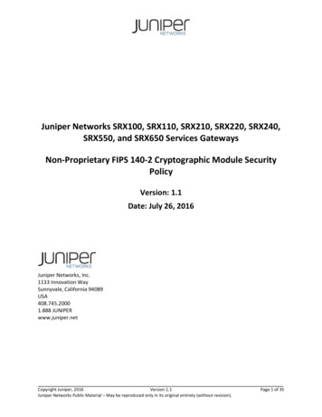
Juniper Networks EVPN Implementation for Next-Generation Data Center ArchitecturesWhite PaperExecutive SummaryTraditionally, data centers have used Layer 2 technologies such as Spanning Tree Protocol (STP), multichassis linkaggregation group (MC-LAG), and Transparent Interconnection of Lots of Links (TRILL) for compute and storageconnectivity. As the design of these data centers evolves to scale out multitenant networks, a new data centerarchitecture is needed that decouples the underlay network from a tenant overlay network with technologies such asVirtual Extensible LAN (VXLAN). Using a Layer 3 IP-based underlay coupled with a VXLAN-EVPN overlay, data centerand cloud operators can deploy much larger networks than are otherwise possible with traditional L2 Ethernet-basedarchitectures. With overlays, endpoints (servers or virtual machines) can be placed anywhere in the network and remainconnected to the same logical L2 network, enabling the virtual topology to be decoupled from the physical topology.IntroductionThe current data center network is coming under pressure due to a number of major trends1: Cloud-based resources and services are becoming an increasingly important part of the enterprise’s IT strategy,requiring a high-performance network architecture that doesn’t compromise security or performance. End users require anytime, anywhere access and high levels of responsiveness, which are becoming harder andharder to achieve with today’s network architectures.These trends are driving data center architects to reenvision the network with three key goals in mind: Scalability: Some enterprises are accommodating growth by increasing their use of cloud services, while othersare deploying their own private and hybrid clouds. Service providers must grow rapidly to have sufficient capacityto meet demand. Today’s networks are often too rigid and difficult to change to support the scalability needs ofthe large enterprise and service provider. New ways to scale the tenants are required in cloud data centers. Oneexample of such a protocol is VXLAN, which scales the number of tenants in a cloud data center to 16 million bydecoupling the tenants’ state from the state of an underlying network by tunneling it over an underlay network. Operational efficiency: As enterprises expand their geographic reach, they face problems relating to physicaldistance between data centers and users, as well as shrinking maintenance windows due to around-the-clockoperations. The new data center network must support application mobility, allowing network administrators toeasily migrate applications within the data center and between data centers for business continuity, maintenancewithout downtime, and load balancing. High performance: End users often complain about poor response times and even outages of business-criticalapplications caused by bandwidth limitations and latency problems. The new data center needs technologies suchas multipathing and control plane learning can optimize network traffic flows, rein in network faults, and ensuremaximum utilization of bandwidth.The key problem with today’s network is that applications are tied to the physical network topology, which has a numberof negative implications: Application scalability is hampered by the network’s inability to scale. Applications cannot easily be moved within the data center or to other data centers. The rigid connection between applications and physical infrastructure makes it difficult to take advantage of cloudservices.Transforming the Data Center Network with VXLAN and EVPNIn the traditional data center, network architects use VLANs to create L2 logical networks that provide security bysegregating users and applications, and they improve performance by limiting broadcast traffic.Layer 2Layer 2VMVMLayer 2VMVMVMFigure 1: Layer 2 logical change-2015/1 2015, Juniper Networks, Inc.3
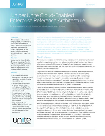
Juniper Networks EVPN Implementation for Next-Generation Data Center ArchitecturesWhite PaperHowever, this architecture is difficult to scale. The VLAN specification (IEEE 802.1ad) provides a relatively small addressspace which results in a maximum number of 4,096 VLANs. There is a one-to-one mapping between VLANs andlogical networks; therefore, the number of logical networks in the data center is also limited to 4,096. Multitenancyenvironments usually support a large number of users, each of whom may need multiple logical networks, so it’srelatively easy to run up against this limit.Another problem with the VLAN approach is that it constrains the movement of virtual machines (and thus theapplications associated with those VMs) to the physical hardware environment hosting the VLANs. Moving anapplication to another location in the data center or to another data center is a cumbersome and error-prone process; inpractice, most network administrators avoid doing so unless absolutely necessary.VXLAN OverviewThe VXLAN (standard IETF RFC7348) takes a major step in resolving these problems. VXLAN enables networkadministrators to create logical L2 networks across different L3 networks. VXLAN has a 24-bit Virtual Network ID (VNID)space, which allows for 16 million logical networks. Implemented in hardware, VXLAN supports transport of nativeEthernet packets inside a tunnel encapsulation. VXLAN has become the de facto standard for overlays terminated onphysical switches and is supported in Juniper Networks QFX5100 and QFX10000 switches, EX9200 Ethernet Switches,and MX Series 3D Universal Edge Routers.VXLAN overlays offer a number of benefits: Elimination of Spanning Tree Protocol (STP) Increased scalability Improved resiliency Fault containmentLayer 3 IP Fabric VXLAN overlayPODPODPODApp 1App 2App 3App 4App 5Figure 2: Application mobility across performance-optimized data centers (PODs)Data Center Control PlanesThe VXLAN abstraction does not change the flood and learn2 behavior of the Ethernet protocol, which has inherentlimitations in terms of scalability, efficiency, and utilization.VXLAN can be deployed as a tunneling protocol across an L3 Clos data center without a control plane protocol. Twoprimary methods exist for doing this: VXLAN with a multicast-enabled underlay, and static unicast VXLAN tunnels. Whileboth are viable options for eliminating L2 in an underlay, and with it L2 protocols, neither solves the inherent flood-andlearn problem, and both are difficult to scale to large multitenant environments.The solution is to introduce a control plane to minimize flooding and facilitate learning. To facilitate learning, the controlplane distributes end host information to Virtual Tunnel End Points (VTEPs) in the same segment.2When a switch receives a broadcast or multicast frame or a unicast frame for which it lacks the destination MAC address and port, it “floods” the frame out all of its portsexcept the input port. A switch “learns” an incoming frame by adding the frame’s source port and MAC address to the switch’s MAC address table. 2015, Juniper Networks, Inc.4
Juniper Networks EVPN Implementation for Next-Generation Data Center ArchitecturesWhite PaperMultiprotocol BGP (MP-BGP) addresses the flood and learn problem. MP-BGP allows the network to carry bothL2 media access control (MAC) and L3 IP information at the same time. Having the combined set of MAC and IPinformation available for forwarding decisions allows optimized routing and switching. This extension that allows BGP totransport L2 MAC and L3 IP information is called Ethernet VPN (EVPN).EVPN solves the flood and learn problem. The emergence of VXLAN as the overlay protocol of choice for IP fabricsmeans that EVPN can use VXLAN for transport, breaking away from the traditional MPLS transport requirement.Furthermore, because it is based on standards3, EVPN also complements software-defined networking (SDN) with itssupport on different controllers.EVPN OverviewControl-based protocols like EVPN, virtual private LAN service (VPLS), and even L2VPN solve the legacy flood-andlearn problem. However, they have predominantly been MPLS driven. Given the advent of VXLAN as an overlay protocolof choice for IP fabrics, EVPN breaks away from the traditional MPLS transport requirement by using VXLAN as thetransport. The next sections of this paper delve into the advantages of EVPN in data center deployments, the differencesfrom MPLS-based EVPN, and deployment considerations.EVPN’s advantages, include:Improved network efficiency Reduced unknown-unicast flooding due to control-plane MAC learning Reduced Address Resolution Protocol (ARP) flooding due to MAC-to-IP binding in control plane Multipath traffic over multiple spine switches (VXLAN entropy) Multipath traffic to active/active dual-homed server Distributed L3 gateway: Virtual Machine Traffic Optimization (VMTO)Fast convergence Faster reconvergence when link to dual-homed server fails (aliasing) Faster reconvergence when a VM movesScalability Very scalable BGP-based control planeFlexibility Easy integration with L3VPNs and L2VPNs for Data Center Interconnect (DCI) BGP-based control plane that provides ability to apply fine-grained policiesEVPN is the only completely standards-based solution that offers these benefits for a data center control planeprotocol.3The relevant EVPN standards include RFC 4364, BGP/MPLS IP Virtual Private Networks (VPNs); RFC 4761, Virtual Private LAN Service (VPLS) Using BGP for AutoDiscovery and Signaling; and RFC 7432, BGP MPLS-Based Ethernet VPN 2015, Juniper Networks, Inc.5
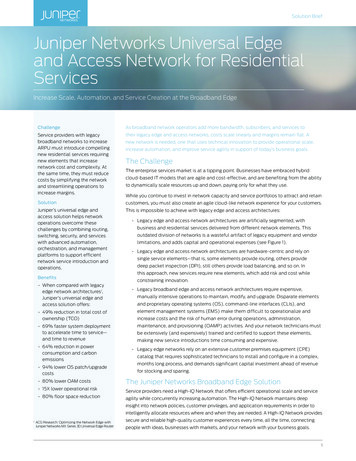
Juniper Networks EVPN Implementation for Next-Generation Data Center ArchitecturesWhite PaperEVPN ConceptsSpine SwitchProvider Core (P)HostLeaf SwitchCustomer Edge (CE)Provider Edge (PE)VTEPVXLAN TunnelEndpointVXLAN TunnelMP-IBGP SessionEVPN Instance (EVI) Virtual SwitchBridge Domain (BD) VLANFigure 3: EVPN terminologyFigure 3 shows two leaf (“top of rack”) switches in an L3 Clos topology. Between these two devices are N number of IPtransport switches/routers, or “Provider Core” devices.EVI EVPN Instance spanning the provider edge (PE) devices participating in that EVPN.MAC-VRF: A virtual routing and forwarding table for MAC addresses on a PE device. A unique route distinguisher (RD)is defined per MAC-VRF.ES Ethernet Segment. Each Ethernet Segment needs a unique identifier in an EVPN. When a customer site isconnected to one or more PE devices via a set of Ethernet links, this set of Ethernet links constitutes an ES.ESI Ethernet Segment Identifier. For a multihomed site, each ES is identified by a unique non-zero identifier calledan Ethernet Segment Identifier (ESI). In general, an Ethernet Segment should have a non-reserved ESI that is uniquenetwork wide (i.e., across all EVPN instances on all PE devices).Attached to the leaf switches (or “provider edge”), are hosts (i.e., servers, storage, or any bare-metal device), which werefer to as customer edge (CE) devices.Between leaf devices, we establish an MP-BGP session, which EVPN uses to distribute routes to be used in the overlaycontrol protocol.EVPN introduces the concept of Route Types. At the time of publication of this document, there are five. Route Type 1: Ethernet Auto-Discovery (AD) Route-- These are advertised on a per EVI and per ESI basis. The Ethernet auto-discovery routes are required when a CEdevice is multihomed. When a CE device is single-homed, the ESI will be zero. Route Type 2: MAC/IP Advertisement Route-- EVPN allows an end host’s IP and MAC addresses to be advertised within the EVPN network layer reachabilityinformation (NLRI). This allows for control plane learning of end systems MAC addresses. Route Type 3: Inclusive Multicast Ethernet Tag Route-- This route sets up a path for broadcast, unknown unicast, and multicast (BUM) traffic from a PE device to theremote PE device on a per VLAN, per ESI basis. Route Type 4: Ethernet Segment Route-- ESI allows the CE device to be multihomed to two or more PE devices—in single/active or active/active mode.PE devices that are connected to the same Ethernet Segment will discover each other through the ES route. Route Type 5: IP Prefix Route-- (Optional) This allows IP Prefix Route encoding for inter-subnet forwarding. 2015, Juniper Networks, Inc.6
Juniper Networks EVPN Implementation for Next-Generation Data Center ArchitecturesWhite PaperEVPN Remote MAC LearningOnce an EVPN MP-BGP session is established between two devices, there are various types of reachability informationthat the EVPN control plane will advertise.The first we will discuss is an EVPN Type 2 route.Spine Switch S1Host H1Leaf Switch L1Leaf Switch ISpine Switch S2MP-IBGPHost H210.10.10.22/245:5:5:5:1Route TypeMAC/IP Advertisement Route (Type 2)Route Distinguisher (RD)RD of red EVI on leaf switch L2Ethernet Segment Identifier (ESI)0 (single homed host)Ethernet Tag IDGlobal VXLAN VNID of bridge domainMAC AddressMAC address of host H2 (5:5:5:5:5:1)IP AddressIP address of host H2 (10.10.10.22) **MPLS label 1 MPLS label 2VNIDNext-hopLoopback IP address of L2 (4.4.4.4)Extended CommunityRoute-targets (Red)Other attributes (Origin, AS-Path, Local-Pref, .).Figure 4: Remote learning (MAC/IP advertisement, EVPN Type 2 route)In Figure 4, Leaf Switch L2 locally learns host H2’s MAC address through traditional L2 learning. Optionally, it may alsolearn the IP-to-MAC binding through either Dynamic Host Configuration Protocol (DHCP) or ARP snooping.In a traditional flood-and-learn network, Leaf Switch L1 would not learn the MAC address of H2 until either H2 has senttraffic to H1, or H1 has received BUM traffic from H2 (i.e., an ARP request). Until Leaf Switch L1 has knowledge of H2’sMAC address, any traffic from H1 towards H2 will be flooded as unknown unicast across all leaf switches throughout thenetwork in the same ES.With EVPN, on the other hand, as soon as Leaf Switch L2 locally learns Host H2’s MAC address, it immediately advertisesthis information via a Type 2 route, to all of its MP-BGP peers belonging to the same VXLAN VNID. This is one primarybenefit of an EVPN control plane.EVPN Server MultihomingServer multihoming to redundant top-of-rack devices is a common requirement in data centers. Traditionally, thisrequirement required vendor proprietary solutions such as multichassis link aggregation (MLAG), multichassis linkaggregation group (MC-LAG), Virtual Chassis port (VCP), stacking, and Virtual Chassis. While each solution has itsmerits, it does require the same vendor across these devices, and in the case of MLAG/MC-LAG, multihoming is limitedto two PE devices.EVPN, on the other hand, is a standards-based multihoming solution, scales horizontally across any number of PEdevices, and seamlessly integrates into a multivendor, L3 Clos fabric.For EVPN server multihoming, a new type of route is required representing an ESI. This is an EVPN Type 1 route. 2015, Juniper Networks, Inc.7
Juniper Networks EVPN Implementation for Next-Generation Data Center ArchitecturesWhite PaperETHERNET AUTO-DISCOVERY (TYPE 1) ROUTESPER ETHERNET SEGMENT (ES): MULTIPATHING AND FAST CONVERGENCENLRIRoute TypeEthernet Auto-Discovery Route (Type 1)Route Distinguisher (RD)RD of EVI on leaf switch LS2 (contains IP of LS2)Ethernet Segment ID (ESI)0:1:1:1:1:1:1:1:1:1Ethernet Tag IDMAX-ETMPLS label0Extended communitiesESI Label Extended Community: Single-Active Flag false (0) ESI Label nullNext-hopLoopback IP address of LS2Other attributes (Origin, AS-Path Local-Pref, :1:1MP-IBGPEthernet Auto-Discovery (Type 1) RouteFigure 5: EVPN Type 1 advertisement, ESIIn Figure 5, H2 is multihomed via a standard link aggregation group (LAG) to both LS2 and LS3 in the same L2 domain.Both LS2 and LS3 advertise direct reachability to this L2 segment, or ESI, via a Type1 route to LS1.Type 1 routes do not advertise MAC address(es) learned on this ESI. For MAC reachability, a Type 2 route is required.In the simplest case, we can assume that LS2 and LS3 have both learned H2’s MAC address.MAC / IP ADERTISEMENT (TYPE 2) ROUTESREVISITED - FOR MULTIHOMED HOSTSNLRIRoute TypeMAC/IP Advertisement Route (Type 2)Route Distinguisher (RD).Ethernet Segment Identifier (ESI)0:1:1:1:1:1:1:1:1:1Ethernet Tag IDVNIDMAC AddressMAC address of host H2 (5:5:5:5:5:1)IP AddressIP address of host H2 (10.10.10.22)MPLS label 1 MPLS label 2VNIDNext-hopLoopback of LS3Other attributes (Origin, AS-Path, Local-Pref, .10.22/245:5:5:5:5:10:1:1:1:1:1:1:1:1:1MAC/IP Advertisement (Type-2) Route with next-hop LS3Figure 6: EVPN Type 2 advertisement with associated ESI 2015, Juniper Networks, Inc.8
Juniper Networks EVPN Implementation for Next-Generation Data Center ArchitecturesWhite PaperIn Figure 6, LS1 receives a Type 2 advertisement for H2’s MAC from LS3, with associated ESI 0:1:1:1:1:1:1:1:1:1; it will similarlyreceive a Type 2 advertisement for H2 from LS2 on the same ESI (not shown), and therefore will know H2 is reachablevia both peers.Each VXLAN tunnel is multipathed over the spine S2LS3Bridge Domain Forwarding TableDest MACNext-hop5:5:5:5:5:1ECMP: VNID 1 over . VTEP1 . VTEP2Figure 7: Multipathing from LS1 to H2 via LS2 and LS3Figure 7 shows how LS1 will multipath via its VXLAN tunnels to both LS2 and LS3 to reach H2. A problem arises, however,when only one of the LS2/LS3 pairs has learned H2’s MAC address (see Figure 8). For this scenario, we require EVPNaliasing in order to achieve multipathing (see Figure 9).1.2.3.4.Host H2 sends all traffic over one LAG member to leaf switch LS2 (not to LS3)Leaf switch LS3 does not learn the MAC of LH2Leaf switch LS3 does not advertise a route for the MAC of H2Leaf switch LS1 does not load-balance the traffic to H2 – it only sends traffic to LS2MAC/IP Advertisement (Type 2) Route for host H2MP-IBGPH11LS1H2LS2LS34LAG2MP-IBGPMAC/IP Advertisement (Type 2) Route for host H23Figure 8: Multipathing failure from LS1 to H2 via LS2 and LS3, without aliasing 2015, Juniper Networks, Inc.9
Juniper Networks EVPN Implementation for Next-Generation Data Center ArchitecturesWhite PaperWe revisit this scenario with aliasing in Figure 9 below.1. LS1 receives Ethernet Auto-Discovery (type 1) Route from both LS2 and LS32. LS1 receives MAC/IP Advertisement (type 2) Route only from LS2LS1 knows on which ESI host H2 is locatedLS1 knows that the ESI on which H2 is located is reachable via LS2 and LS33. LS1 can ECMP traffic to host H2 over both VTEPs to LS2 and LS3Ethernet Auto-Discovery (Type 1) Route for ESI 0:1:1:1:1:1:1:1:1:11MAC/IP Advertisement (Type 2) Route for host H2 on ESI :1:1:1:1:1:1:1:1MP-IBGP1Ethernet Auto-Discovery (Type 1) Route for ESI 0:1:1:1:1:1:1:1:1:1Figure 9: Multipathing from LS1 to H2 via LS2 and LS3, with aliasingSince H1 learns of H2’s MAC address via a Type 2 route from LS2 with ESI 0:1:1:1:1:1:1:1:1:1, it can therefore determine thatH2’s MAC is also reachable via LS3 because of LS3’s Type 1 advertisement of this same ESI.EVPN Fast ConvergenceIn typical flood-and-learn protocols as well as legacy L2 control planes, a link failure with reachability to multiple, orhundreds, of MAC addresses can lead to slow convergence times.Reconvergence after a failure is slow:1. Connection between leaf switch LS3 and switch S goes down2. Egress leaf switch LS3 withdraws routes for all hosts H2 . H100 behind switch S3. Ingress leaf switch LS1 removes all withdrawn routes from the forwarding thdraw MAC/IP Advertisement (Type 2) Route for host H22Virtualized Server.Withdraw MAC/IP Advertisement (Type 2) Route for host H3Withdraw MAC/IP Advertisement (Type 1) Route for host H100Figure 10: Slow convergence with individual MAC advertisements 2015, Juniper Networks, Inc.10
Juniper Networks EVPN Implementation for Next-Generation Data Center ArchitecturesWhite PaperIn figure 10, we’ve introduced an intermediate multihomed L2 switch (S1) between LS2 and LS3 and hosts H2-H
transport L2 MAC and L3 IP information is called Ethernet VPN (EVPN). EVPN solves the flood and learn problem. The emergence of VXLAN as the overlay protocol of choice for IP fabrics means that EVPN can use VXLAN for transport, breaking away from the traditional MPLS transport requirement.